
Subscribe to Our Youtube Channel
Related Manuals for RHINO RMCS-2313


Summary of Contents for RHINO RMCS-2313
- Page 1 Single Channel DC Motor Driver 6V-30V 20Amp RMCS – 2313 Operating Manual v1.0 P a g e https://www.robokits.co.in/...
- Page 2 Contents Introduction – Technical specs ............................ 3 Pin configurations……………………………………………… …………………………………… …………………… … .…………………………………………..4 Switch settings of the drive….….……………………………………………………………………………………………………………………………………….6 Connection diagram of the drive.. …………………………………………… …………………………………………… ………………..……………………..7 Motor control using microcontroller and potentiometer…………………………………………………………………………………………………..8 Code for motor control with Arduino…………………………………………………………………………………………………………….………………….10 Code for speed control from potentiometer……………………………………………………………………………………………………………………...12 P a g e https://www.robokits.co.in/...
-
Page 3: Technical Specifications
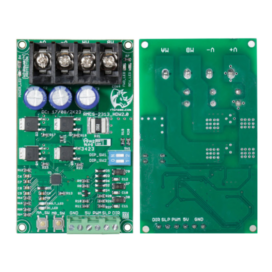
Introduction : The Rhino single channel Driver 20A enables control of a high-power brushed DC motor from 6V to 30V. With full discrete NMOS H-Bridge design, this motor driver is able to support 20Amp continuously for the motor without any heat-sink The onboard test buttons and motors output LEDs allow functional test of the motor driver in a quick and convenient way without hooking up the host controller. - Page 4 Pin Configuration of the Drive: Fig 1: Description Description CURR_SWITCH OC_LED MA_SW FAULT_LED MB_SW POWER_LED (POWER SUPPLY) (POWER SUPPLY) REV_LED FWD_LED P a g e https://www.robokits.co.in/...
- Page 5 NAME FUNCTION Turn on when current limiting is in action. Current limit threshold OC_LED is depending on the board temperature. FAULT_LED Turn on during Under voltage, Shutdown or Hardware fault POWER_LED Indicates power is on. If its not on then check your connections. Connect positive of power supply.
-
Page 6: Peak Current
Switch Settings of the Drive: Fig 2: Peak current Switch S1 Switch S2 Motor M1 60 Amps 40 Amps 16 Amps P a g e https://www.robokits.co.in/... -
Page 7: Connection Diagram
Connection Diagram Hardware Connection : Fig 3: P a g e https://www.robokits.co.in/... - Page 8 Controlling : As depicted in fig 3, there is a provision to connect a motor to the driver : To initiate a test run of the motors, you can conveniently utilize the push buttons integrated into the driver, specifically MA_SW and MB_SW.
- Page 9 Fig 4: P a g e https://www.robokits.co.in/...
- Page 10 Sample code for motor control using Arduino : /* Connections of RMCS-2313 with arduino : * RMCS2313 : Arduino pins * Sleep : 9 * GND : GND * Dir : 7 * pwm : 11 */ const int Sleep = 9; //Sleep pin for the motor const int Dir = 7;...
- Page 11 Fig 5 : 11 | P a g e https://www.robokits.co.in/...
- Page 12 //Small delay ht © Rhino Motion Controls, 2023 Neither the whole nor any part of the information contained in, or the product Copyrig described in this manual, may be adapted or reproduced in any material or electronic form without the prior written consent of the copyright holder.
Need help?
Do you have a question about the RMCS-2313 and is the answer not in the manual?
Questions and answers