
Subscribe to Our Youtube Channel
Related Manuals for ePropulsion X20 Series


Summary of Contents for ePropulsion X20 Series
- Page 1 X20 User Manual Model: X20-L, X20-XL 2023.09 Version 1.0 Copyright © ePropulsion Technology Limited...
-
Page 3: Acknowledgement
Before use of the product, please read this user manual thoroughly to understand the correct and safe operations. By using this product, you hereby agree that you have fully read and un- derstood all contents of this manual. ePropulsion accepts no liability for any damage or injury caused by operations that contradict this manual. - Page 4 You need to be alert, perform relevant operations reasonably, and pay atten- tion to safety. when installing, operating, maintaining or serving ePropulsion products, there are many safety risks in the process. You need to be alert, perform relevant operations reasonably, and pay attention to safety.
-
Page 5: Product Serial Number
Product Serial Number Below picture indicates the serial numbers of X20 Outboard Motor. Please note the position of the serial numbers and record them for access to warranty service and other after-sale services. -
Page 6: Table Of Contents
Table of Contents Acknowledgement ....................1 Using This Manual ....................1 Safety Warning ....................... 1 Product Serial Number ................... 3 1 Product Introduction .................... 8 1.1 In the Package ......................8 1.1.1 X20 Packaging List ..................8 1.1.2 Optional Accessory List ................10 1.1.3 Installation Tools List ................ - Page 7 4.2.1 Make a cable (crimped cable connector) ..........32 4.2.2 Cable connection at the bus box ............. 33 4.2.2.1 Required accessories and tools..........33 4.2.2.2 Installation ..................33 4.2.3 Connecting the DC-DC Module and 12V Battery ........36 4.2.3.1 Required Accessories and Tools ..........36 4.2.3.2 Installation Steps .................
- Page 8 5.6.3 General setting ..................63 5.6.3.1 System firmware information ............. 63 5.6.3.2 Maintenance - All maintenance timing tips........ 64 5.6.3.3 ePropulsion Connectivity Service ..........65 5.7 Operation ......................67 5.7.1 Check before start ..................67 5.7.2 Starting the Outboard Motor ..............67 5.7.3 Adjust power .....................
- Page 9 6.1 Collision ........................ 83 6.2 Sodden Outboard ....................83 6.3 Overtemperature Protection ................83 7 Maintenance ...................... 84 7.1 Maintenance ......................84 7.1.1 Routine maintenance ................84 7.1.2 Machine maintenance ................85 7.2 Partial Maintenance and Care Guidelines ............86 7.2.1 Gearbox Oil Replacement Procedure ............
-
Page 10: Product Introduction
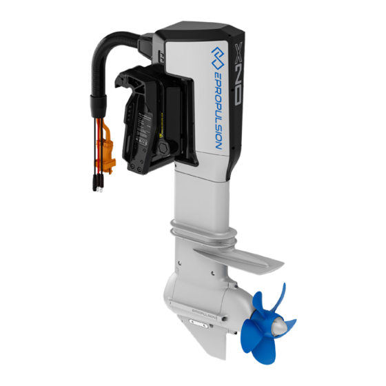
1 Product Introduction The X20 Electric Outboard Motor is an electric propulsion system with an input power of 20kW. It can be controlled using the smart tiller, digital helm, smart throttle, and smart display 5''. The X20 Electric Outboard Motor is environmentally friendly, clean, and efficient. It is availa- ble in two models: X20-L and X20-XL. - Page 11 Items Qty. Figure Function eSSA Extend the Communication communication Extension Cable distance of the CAN communication cable Heating Shrinking Protect the main power Tube cable after stripping it black 红色 Retrofit terminal for Cable connector rear end of main power 黑色...
-
Page 12: Optional Accessory List
Other accessories not included in the package are also required to operate the outboard motor such as propellers, smart tiller, digital helm, smart throttle, smart display 5'', G102 battery, battery charger, and communication cables. Users can buy official accessories provided by ePropulsion Technology authorized dealers. - Page 13 Items Figure Function Suitable for heavy-load X20/X20 Propeller scenarios. Recommended for 15'' x 10 3/4'' LH use in twin-motor or multi- motor X20/X20 Propeller 13 3/8'' x 16 3/4" Suitable for light-load scenarios X20/X20 Propeller Suitable for light-load scenarios 13 3/8'' x 16 3/4" Recommended for use in twin- motor or multi-motor G102 Battery...
- Page 14 Items Figure Function Outboard motor steering Digital Helm control Start, stop the motor and Smart Throttle control the power output Display system information Smart Display 5'' such as power, speed, battery level and set system functions DC-DC DC to charge the 12V battery Use when outboard motor GPS signal is weak.
- Page 15 12V equipment, ensure this charging capacity meets the battery's requirements. When selecting and purchasing propellers, it is recommended to consult ePropulsion authorized dealers and consider the following references: If the expected speed is 25km/h or less, it is recommended to choose the X20/X40 •...
-
Page 16: Installation Tools List
1.1.3 Installation Tools List Before installing the outboard motor, users or machine installation operators need to prepare the neceSSAry tools for outboard motor installation, propeller installation, wiring arrangement, fixation, and connection. Tool Specification Qty. Purpose To disassemble the machine's 4mm, suitable for M5 hexagon top cover, facilitating the M5 Hex Wrench installation of eye bolts and... -
Page 17: Parts And Diagram
Tool Specification Qty. Purpose Electric Drill / Drill holes in the boat for Hole-Making Hole requirement: φ13mm machine installation Equipment Hole-making Drill holes in the boat for Hole requirement: φ13mm Tools machine installation Hole-making Meet the hole size: 100mm Boat hole routing Tool Apply to the bolt position after Sealant... - Page 18 Fixed Position of Eye Bolt Fixed Position of Eye Bolt ber) ber) Figure 1-2 Communication Interface Communication Interface for Smart Tiller for Interactive System High Voltage 4G Antenna Interlock Interface Interface Communication Interface Communication Interface Sound and Light for Smart Tiller for Interactive System NMEA2000 Alarm Interface...
-
Page 19: Specification
1.3 Specification Model X20-L / X20-XL Rated input power 20 kW Recommended battery ePropulsion Lithium Iron Phosphate Battery Rated input voltage 96 Vdc Input voltage range (high voltage) 86 - 115 Vdc Input voltage range (low voltage) 10.5 - 16 Vdc Weight L: 76.5 kg XL: 78 kg... -
Page 20: Model And Shaft Length Selection
1. Only adults who have fully read and understood this manual are allowed to operate this product. Read the full user manual carefully before operation, ePropulsion accepts no liability for any damage or malfunction caused by operations violating this manual. - Page 21 If there is more than one person onboard, make sure you are not the only one onboard who knows how to operate this pod drive system to help in case of an unforeseen emergency. 5. Follow the user manual to mount this product to your boat. It is suggested to have certified boat builders or professional installers to install this outboard motor to your boat.
-
Page 22: Declaration Of Conformity
Product: Electric Outboard Motor Model: X20, X20-L,X20-XL We Guangdong ePropulsion Technology Limited, hereby, declares that this equip ment is in compliance with the applicable Directives and European Norms, and amendments. The object of the declaration is in conformity with the following directives:... -
Page 23: Statement
1.7 Statement Operation is subject to the following three conditions: (1) This device may not cause harmful interference, and (2) this device must accept any interference received, including interference that may ca use undesired operation. (3) This device has been evaluated to meet general RF exposure requirement. The device can be used in portable exposure condition without restriction Note: This equipment has been tested and found to comply with the limits for a Class B digital device, pursuant to part 15 of the FCC Rules. These limits are designed to provide reasonable protectio n against harmful interference in a residential installation. This equipment generates, uses and c an radiate radio frequency energy and, if not installed and used in accordance with the instructio ns, may cause harmful interference to radio communications. However, there is no guarantee th at interference will not occur in a particular installation. If this equipment does cause harmful int erference to radio or television reception, which can be determined by turning the equipment off and on, the user is encouraged to try to correct the interference by one or more of the following measures: —Reorient or relocate the receiving antenna. —Increase the separation between the equipment and receiver. —Connect the equipment into an outlet on a circuit different from that to which the receiver is co nnected. —Consult the dealer or an experienced radio/TV technician for help. 1.8 Correct Disposal of this product This marking indicates that this product should not be disposed with other household wastes throughout the EU. -
Page 24: Unboxing
2 Unboxing 2.1 Safety Notice Use appropriate safety equipment, including gloves, safety shoes, and other protective tools. Familiarize yourself with all safety measures before proceeding with the operation. Due to the product's substantial weight, at least two people are required for handling. 2.2 Tools and Equipment Required for Unpacking Unpacking tools: such as a rubber hammer, phillips screwdriver, etc. - Page 25 Step 3 Pry open the fasteners between the wooden box and the base, then lift the entire wooden box off the base. Packaging Box Cover User Manual Packaging Box Cover Buffer Material Packaging Box Cover User Manual User Manual Buffer Material Cable Accessories Box Buffer Material Other Accessories...
-
Page 26: Disposal Of Packaging Materials
Please check the product for any damages or missing parts. If there are any issues, please contact customer support. During the unpacking process, be careful to avoid damaging the product. Check all accessories and ensure they are complete. 2.5 Disposal of packaging materials 1. -
Page 27: Series Outboard Motor Installation
3 X-Series Outboard Motor Installation The quality of the installation plays a crucial role in the overall reliability of the entire system. Key aspects such as securing the machine to the boat, propeller installation, and wiring connections must be carefully considered and adhered to in order to ensure stable and reliable system operation. -
Page 28: Outboard Motor Installation
(hole size φ90~φ100mm, or adjust based on actual connector shapes) and secure the cable with protective measures. 广东逸动科技有限公司 单位:mm Guangdong ePropulsion Technology Limited 100mm Figure 3.2 Step 2: Removing the Machine Cover Before lifting, tidy up the cables and secure them to the motor. Remove the four M5 screws from the outboard motor cover. - Page 29 M5x10 Hexagon Screw 60mm Top Cover 18mm 广东逸动科技有限公司 单位:mm Guangdong ePropulsion Technology Limited 13mm Figure 3.4 Lifting objects hazard: pay attention to safety when hoisting equipment or objects nearby to avoid being hurt or crushed by falling objects. 13mm 88mm...
-
Page 30: Propeller Installation
3.3 Propeller Installation Refer to the following steps to install or replace the propeller: 4mm Inner 1. Turn off the system or turn off the 12V powr supply. Hexagon Wrench 2. Straighten and remove the cotter pin. M5 Inner Hexagon Screw 3. -
Page 31: Notice
It is mandatory to shut down and disconnect the power supply of the outboard motor before removing and installing the propeller. Cautious: There are various safety risks during the installation process, so it is essential to be vigilant and perform operations with caution to ensure safety. During trial runs, please stay away from the propeller to avoid any risk of being cut or injured. -
Page 32: Connections
4 Connections 4.1 X20 Various Scenario System Connection 4.1.1 Single System Connection 14. eSSA Communication 3-way T Connector 15. Outboard Communication Cable (Come with Motor) 1. X20 Electric Outboard Motor 16. eSSA Communication 5-way T Connector 2. 12V battery 17. G102-100 Battery Grounding Line 3. -
Page 33: Twin System Connection
Whether the negative pole of the 12V battery is grounded needs to be adjusted according to local regulations. The X20 machine supports a maximum of two consoles and four motors operation. For connection and cautions not mentioned in the user manual, please contact ePropulsion's authorized dealer for assistance. -
Page 34: High Voltage Cables Connection
4.2 High Voltage Cables Connection 4.2.1 Make a cable (crimped cable connector) When you receive the cable, "Motor to bus box power cable" and "Battery to bus box power cable" are integrated. You need to cut one of the integrated cables from an appropriate position according to the placement and distance of the battery, bus box and outboard motor on board. -
Page 35: Cable Connection At The Bus Box
≤0.3mm 3. Fit heat shrink tubing over the joints between the terminals and the inner cables, and (separately) over the shielding layer. Leaving the joints or the shielding exposed to air may result in insulation and system failure. Please use the crimping tool corresponding to the specifications of the terminal to ensure a proper crimping process. - Page 36 (2) Install the cable connector of 4 groups of cables It is neceSSAry to install 4 groups of cables ( ② , ③ , ④ and ⑤ ) of 4.3.1.1, a total of 8 cables to the terminals on the top. For the functions of each interface on the bus box, see the corresponding logo of the interface.
- Page 37 5. Bus box installation: The bus box shall be fixed with M6 self-tapping screws or bolts based on the actual installation position, and the M6 fastening torque is 8N·m. The bus box needs to be installed on a flat plane, and it needs to be far away from the position with water risk and heat source.
-
Page 38: Connecting The Dc-Dc Module And 12V Battery
4.2.3 Connecting the DC-DC Module and 12V Battery 4.2.3.1 Required Accessories and Tools ① Bus box part completed in step 4.2.2 ② M6 hexagon wrench ③ 12V battery (purchased by the user) ④ Hex socket wrench suitable for 12V battery terminal screws and nuts 4.2.3.2 Installation Steps Step 1: Connecting the Bus Bar with the DC-DC Module Securely fasten the input terminal of the DC-DC module to any of the three interfaces labeled... -
Page 39: Connecting The G102-100 Battery
Step 3: Connecting the DC-DC Output and 12V Battery Figure 4.9 When connecting DC-DC and 12V battery, pay attention to avoid short circuits. 4.2.4 Connecting the G102-100 Battery 4.2.4.1 Required Accessories and Tools ① G102-100 battery ② Bus box part completed in step 4.2.3 4.2.4.2 Installation Steps Insert the aviation pconnector of the bus box part into the corresponding color interface of the G102-100 battery. -
Page 40: Connecting The Outboard Motor's Main Power Cable
4.2.5 Connecting the outboard motor's Main Power Cable 4.2.5.1 Required Accessories and Tools ① Outboard motor ② Bus box, DC-DC module, and 12V battery connected in step 4.2.3 If you need to extend the 12V cable, prepare the following: ① 12V extension cable (user should purchase a specified cable not exceeding 3m in length) ②... - Page 41 Press down the black handle to firmly secure the connector. Close the locking mechanism, as shown in Figure 4.15. Handle Latch Figure 4.15 High-voltage interlock pconnector - Installation step 5 You can use an M4x80mm screw to fix the high-voltage interlock pconnector to the boat (user-provided).
-
Page 42: Communication Device And Connection
4.3 Communication Device and Connection 4.3.1 Remote Control Scenario: Connecting Interactive Devices and Accessory Communication Cables Taking the example of a single-machine single-set interactive system with a single group of X20 model batteries, the communication device connection for other scenarios should be based on the "System Device Connection Plan."... -
Page 43: Smart Throttle Connection
Digital helm Smart display CAN comm cables eSSA Communication CAN communication cable (to motor) Cable 1m Smart throttle eSSA Communication 5-way T-connector eSSA Communication eSSA Communication 3-way T-connector Terminators Figure 4.16 4.3.1.2.2 Smart throttle connection Each smart throttle has a BUS port and DUAL port at the bottom. Connect to the other throttle and use as dual-throttle Connect to system... -
Page 44: Grounding
18mm All operations must be done without power. Do not connect or disconnect the cables while there is power. 116mm 120mm 4.4 Grounding In order to ensure safety and stability of system operation, the X series outboard motor (with a 5m grounding line), DCDC module, G102-100 battery, and 12V battery (purchased by the user) must be grounded during system installation. -
Page 45: Purchasing Accessories And Connections
4.5 Purchasing Accessories and Connections The X-series outboard motor already has integrated 4G and GPS modules. Do not cover the machine's head. If the installation environment affects the strength of the 4G and GPS signals, an external 4G and GPS module can be used. 4.5.1 Installation of the 4G Antenna Step 1: Use an M5 hexagon wrench (4mm) to remove the four M5 hexagon cylindrical head screws on... -
Page 46: Installation Of The External Gps Module
Step 4: Fix the 4G antenna on the boat (outdoors). There are two fixing options, as shown in the following images. Antenn Antenn Steel expansion bolt M8*50 (4PCS User provided) Clip Non-concrete wall Lead out Lead out ∅ ∅ Holding rod low loss low loss Diameter... - Page 47 • 3M Adhesive Attachment Use the provided sealing cover of the accessory to secure the adhesive attachment on the specified area at the bottom of the external GPS module. Then, paste it in an open outdoor area. Before pasting, ensure the cleanliness of the pasting area to prevent poor adhesion due to impurities.
-
Page 48: Communication Terminator Connection
4.6 Communication Terminator Connection During the use of the outboard motor, for more stable communication between various components, it is neceSSAry to connect different combinations of communication terminators to the T connector according to the following scenarios. The resistance value of each communication terminator is marked on its tail, as shown in the figure: Using an external GPS module Not using external GPS modules... -
Page 49: Operation
5 Operation 5.1 Smart Throttle Button Functions (single & double throttles) Single-throttle operation Button Function Press and hold down this button for 1 second to power the system on or off. Power Switch console (when two throttles are fitted): When the system is turned on, press the Power button twice on the inactive console to activate it. - Page 50 Dual-throttle operation Button Function Press and hold down this button for 1 second to power the system on or off. Power Switch console: When the system is turned on, press the Power button twice on the inactive console to activate it. Direction holding function or anchor mode: Press twice to enter Hold Hold mode, and when in Hold mode press once to exit.This...
-
Page 51: Start The Machine
Note: The kill switch is placed correctly. Please place a kill switch on either side of the Smart Throttle to start the motor. Please remove the kill switch after the machine is turned off. Stop the outboard motor in emergency by detaching the kill switch. To run the motor again, first attach the kill switch, then start the motor. - Page 52 Step 2: Configure the location of the equipment When there is only one console and one motor, the system will automatically complete the system initialization settings and directly enter the home page. When there are more than one console and more than one propulsion, the user needs to configure the console accessories and the position of the propulsion.
- Page 53 3. Configure smart throttle When it is a single-throttle, manually click any button of the throttle to match successfully. When it is a dual-throttle, click any button of the left and right throttles respectively to match successfully. 4. After console A is configured, the remaining parts will be automatically matched to console B.
-
Page 54: Home Page
5.4 Home Page 16 11 Function Description Setting page Click to go to the setting page. Home page Click to go to the home page. Propulsion page Click to go to the propulsion page. Warning When the system fails, it will prompt a fault icon. System status READY indicates that the system is ready to start. - Page 55 Single motor trim 1. Click or drag up the trim button to view the first-level page displaying the real-time motor tilt angle. 2. Continue dragging up the trim button to view the second-level page. Manual Trim Adjustment: Manually click or drag the bar to adjust the motor's tilt angle. One-Step Tilt: Click the one-step tilt button, and the machine will automatically tilt to the top.
- Page 56 Multiple motors trim 1. Click or drag up the trim button to view the first-level page displaying the real-time motor tilt angle. 2. Continue dragging up the trim button to view the second-level page. Synchronization: When multiple motors are in synchronization, pushing any bar will change the tilt angle of all outboard motors together.
-
Page 57: Propulsion Diagram
5.5 Propulsion Diagram 5.5.1 Control Console Click on the console to view the accessories for each console. -
Page 58: Power Battery
When the accessories fail, the icon will turn orange or red. Click the fault icon to view the detailed fault. 5.5.2 Power Battery The power battery can be clicked to view the remaining power, voltage, and current. -
Page 59: Propeller
5.5.3 Propeller Click on the Motor icon(s) to view current power, rotational speed and cumulative run time. 5.6 Setting The Settings include three major module settings: outboard settings, control settings, and general settings. -
Page 60: Propulsion Setting
Button Function Click to enter the propulsion setting page, you can set the motor OUTBOARD switch and reverse propeller switch. Click to enter the console setting page, you can set single-throttle CONTROL assembly, dual-throttle FN function, Smart display, etc. Click to enter the general setting page to set firmware update, GENERAL maintenance, connectivity and more. -
Page 61: Steering Setting
5.6.1.2 Steering Setting Function Description Adjust steering angle Adjust the maximum steering angle left and right. 5.6.2 Control console Settings 5.6.2.1 Smart throttle settings 1. Single-throttle Settings... - Page 62 Function Description Click and set the smart throttle installation mode to starboard Starboard installation. If it springs back, the setting fails. Click and set the smart throttle installation mode to port installation. Port If it springs back, the setting fails. 2.
-
Page 63: Display Settings
Motor output indication home page will change accordingly after the switch. The unit can be switched between knot, km/h and mile/h. After Units the switch, the speed limit unit of the home page and ePropulsion setting page will be changed accordingly. -
Page 64: Helm Setting
5.6.2.3 Helm Setting Function Description Force feedback Adjust the steering wheel torque force. Number of turns Adjust the number of steering wheel turns... -
Page 65: General Setting
5.6.3 General setting 5.6.3.1 System firmware information Function Description System version Display the propulsion version. Serial Click Device List to go to the device serial number list page. You can number view all device SN and software and hardware version. When there is a new version to be updated, you will be prompted with the content of the new version and the estimated time. -
Page 66: Maintenance - All Maintenance Timing Tips
Device list page 1. Click Reset to reset the device to its factory device state. 2. Device List displays the SN and software and hardware versions of all components of the propulsion. 5.6.3.2 Maintenance - All maintenance timing tips 1. The system automatically calculates the maintenance schedule based on various maintenance items. -
Page 67: Epropulsion Connectivity Service
X20 offers connectivity capabilities by communicating with the ePropulsion cloud through its 4G antenna. You can link your product to the ePropulsion Link, a user-friendly software designed for personal boat owners, enabling them to monitor their boat's status remotely on their mobile devices. - Page 68 To check if a new software version is available, access the boat display through the following path: Settings > General > System Info. If your ePropulsion system is connected to the ePropulsion Link, you will also receive notifications about new software versions within the ePropulsion Link. OTA access can be found on the propulsion system page.
-
Page 69: Operation
30 minutes. After a successful installation, you will see that your system is running the latest version on the boat display, and you will receive a notification of the successful update within the ePropulsion Link. 5.7 Operation 5.7.1 Checks before starting... -
Page 70: Steering Control
If you pull the throttle directly from forward to reverse, the motor will stop briefly before entering reverse gear. This is to protect the gearbox from damage. Neutral Forward Neutral Forward Backward Backward Port Starboard Figure 5.2 5.7.4 Steering Control 5.7.4.1 Steering Control with Digital helm Secure the digital helm on the dashboard using screws, then connect the system's CAN communication cable to the communication interface at the bottom of the digital helm (see... - Page 71 • Tilt Adjustment Button on the Motor Tilt adjustment button on the motor Up button Lower button Figure 5.4 •Tilt Adjustment Button on the Smart Throttle 广东逸动科技有限公司 Remote Control 单位:mm Guangdong ePropulsion Technology Limited Tilt Adjustment Button Figure 5.5 广东逸动科技有限公司 单位:mm Guangdong ePropulsion Technology Limited...
- Page 72 • Tilt Adjustment Button on the Display Figure 5.6 5.7.5.2 Adjusting the Boat's Trim Angle When the boat is planing, raising the bow reduces resistance, improves stability, and enhances efficiency. Typically, the boat's centerline is raised by 3° to 5°. When the bow is raised, the boat tends to turn to one side or the other, requiring compensation during steering.
- Page 73 Excessive inward trim makes the boat "plow" through the water, leading to difficulty in accelerating. Running at high speeds with excessive inward trim can also make the boat unstable. The resistance at the bow significantly increases, making steering difficult and hazardous.
-
Page 74: Hydro Generation Function
5.8 Hydro Generation Function X series outboard can drive the propeller to charge the battery (only the ePropulsion battery) through water flow. The machine will enter the hydro generation state if the following conditions are met: 1. -
Page 75: Idle Mode, Sleep
8000rpm). 5. The battery level is higher than 90%. 6. Only when connecting with ePropulsion batteries, the hydrogeneration function can be turned on. 5.9 Idle Mode, Sleep For convenience and enhenecing experience in various scenarios, the X-series outboard motor is equipped with idle mode, sleep mode, and wake-up function. -
Page 76: Cautions
level. Please charge your battery promptly to avoid any inconvenience during the next voyage. In the event of system malfunctions, we will upload the fault information through the boat network, and registered users can view the relevant information on the App or other platforms. Please refer to section 5.11 for fault handling and contact the after-sales service and dealers to address any issues. -
Page 77: Troubleshooting
5.11 Troubleshooting 5.11.1 Common mechanical troubleshooting Failure Reason Solution Replace the tilt and trim Abnormal tilting Tilt and trim system damage system. Trim limit and release Mechanism damage such as Repair/replacement bracket abnormality trim limit clamp Abnormal steering Steering system damage Replace steering module Outboard motor and hull are not Tighten... -
Page 78: System Troubleshooting List And Treatment Methods
5.11.2 System troubleshooting list and treatment methods Fault position Fault name Fault code Solution 1. Check the external wiring. Encoder fault P101003 2. Replace the rotary encoder. 3. Replace the motor controller. 1. Check the external wiring. Power tube pass- P100F03 2. - Page 79 Fault position Fault name Fault code Suggested measures 1. Overhaul the motor or drive system. The motor 2. Check whether the heat dissipation is seriously P100203 channel is blocked. overheated 3. Check coolant level 1. Check the operating conditions. MOS general P100402 2.
- Page 80 Fault position Fault name Fault code Suggested measures Auxiliary power 1. Check the external input 12V power P130B11 overvoltage supply Auxiliary 1. Check the external input 12V power power supply P130C11 supply undervoltage 1. Check the BMS line and cable 2.
-
Page 81: Lameness
Fault position Fault name Fault code Suggested measures 1. Keep away from strong magnetic Throttle fields and recalibrate calibration data H120203 2. If it occurs repeatedly, contact after- abnormal sales processing Wired remote Abnormal throttle 1. Keep away from strong magnetic operation box H120003 angle... -
Page 82: Temporary Running Mode
Fault position Trigger condition Processing strategy Low SOC Linear power drop High voltage interlock X-ECU failure Close Secondary failure Reduce power by 50% operation Stop the machine first and push the throttle Level three failure again, then limit the power to 10kW, and manually control the steering Electric Secondary failure... -
Page 83: Manual Trim
(3) Secure the sound and light alarm wire in the cable groove. (4) Fix the upper cover. Schematic Diagram of Sound and Light Sound and Light Cable Cable Tray Alarm Interface Alarm Device Figure 5.9 广东逸动科技有限公司 单位:mm Guangdong ePropulsion Technology Limited... -
Page 84: Nmea2000 Device Expansion
5.13.2 NMEA2000 Device Expansion The X-series outboard motor supports external NMEA2000 communication protocol devices. Follow these steps to connect the NMEA2000 device: (1) Remove the machine's upper cover. (2) Connect the NMEA2000 connector as shown in the diagram and tighten it. (3) Secure the NMEA2000 communication line in the cable groove. -
Page 85: Emergency Situations
6 Emergency Situations 6.1 Collision If the outboard strikes some object beneath the water, please follow below procedures. 1. Stop the outboard immediately and then turn off the main switch. 2. Check the mechanical structure to see if there are damages. 3. -
Page 86: Maintenance
7 Maintenance 7.1 Maintenance 7.1.1 Routine maintenance Maintenance Maintenance items Maintenance methods frequency After each use, rinse the soaked and Fresh water flushing splashed parts with fresh water after the After each use after use machine is warped Please lift the machine after each use. If Cleaning of external the surface of the machine is attached to After each use... -
Page 87: Machine Maintenance
7.1.2 Machine maintenance Maintenance cycle Mainten Every other time in First maintenance -ance the future Method of operation Main work items 1000 hours hours hours hours hours hours (Or 3 (Or 6 (Or 1 (Or 6 (Or 1 (Or 4 months) months) year) -
Page 88: Partial Maintenance And Care Guidelines
Tilt the outboard motor to make the oil drain pconnector at the lowest point. Place a pan under the lower oil drain bolt, remove the lower oil drain bolt, then remove the upper oil drain bolt, and completely drain the gear oil. oil injection bolt Figure 7.1 广东逸动科技有限公司 单位:mm Guangdong ePropulsion Technology Limited... - Page 89 Figure 7.2 广东逸动科技有限公司 Step 5: 单位:mm Guangdong ePropulsion Technology Limited Add 500 ml of new gear oil from the oil filling hole. Use a funnel to inject 500ml of gear oil Figure 7.3 广东逸动科技有限...
-
Page 90: Anode Replacement
Step 6: Tighten the oil filling bolt. Tighten the oil injection bolt Figure 7.4 Step 7: Refer to 3.1.3, and install the propeller. When adding gear oil, please add exactly 500 ml. Too little oil can result in insufficient lubrication and reduce the overall lifespan or damage the sealing components. Too much 广东逸动... -
Page 91: Propeller
广东逸动科技有限公司 7.2.3 Propeller 单位:mm Guangdong ePropulsion Technology Limited The propeller is an important component of the outboard motor. To ensure safe navigation and optimal performance of the outboard motor, the propeller should be regularly disassembled and inspected. During the inspection, pay attention to the following: (1) Check if each blade of the propeller has any wear or other damage. -
Page 92: Exterior Surface Of The Outboard Motor
7.2.4 Exterior Surface of the Outboard Motor The exterior surface of the outboard motor is protected by paint. It should be regularly cleaned with marine-grade cleaning agents, waxed, or coated with other protective layers. 7.2.5 Greasing Points Apply lubrication with 2-4-C lubricating grease containing polytetrafluoroethylene to the following lubrication points. -
Page 93: Check Grounding Wires
7.2.6 Check Grounding Wires Inspect each grounding wire to ensure it is securely fastened, as shown in the diagram below. Grounding wire of clamp Grounding wire Grounding wire of clamp of trim & tilt device Figure 7.9 广东 单位:mm Guangdon... -
Page 94: Warranty
(the “ePropulsion Service Partners”) with a minimum maintenance charge per occurrence. In all warranty cases, ePropulsion will only bear the repair cost and other costs (such as those related to product installation, disassembly, transportation, financing, rental, etc.) as a direct result of issues covered by the Limited Warranty only. - Page 95 The average temperature is calculated using the Arrhenius equation; this means that higher temperatures are given a greater weighting. 8.1 Out of Warranty ePropulsion may refuse a warranty claim if: • Any improper operation contradicts what is written in the user manual; • Accident, misuse, dropping, improper care or storage, willful abuse, physical damage, unauthorized repair;...
-
Page 96: Limited Warranty Claim Procedures
6. In case your warranty claim be rejected, a repair/replace cost and fee with round trip delivery cost will be estimated and sent to you for confirmation. ePropulsion Service Partners will only begin the work after your written confirmation. - Page 99 (*In order to validate warranty, please fill in this form first and read the Warranty Policies.) OWNER INFO. Owner Name Address Phone Email DEALER INFO. Store Name Address Phone Email PRODUCT INFO. Date of Purchase (mm/dd/yyyy) Serial No.
- Page 102 Thanks for reading this user manual. If you have any concerns or find any problems while reading, please don't hesitate to contact us. We are delighted to offer service for you. Guangdong ePropulsion Technology Limited Webseite: www.epropulsion.com E-Mail: service@epropulsion.com...
Need help?
Do you have a question about the X20 Series and is the answer not in the manual?
Questions and answers