
Related Manuals for Phenix MRM-200-V2

Summary of Contents for Phenix MRM-200-V2
- Page 1 200 A digital micro-ohmmeter User guide Parts of this manual may differ from your equipment, depending on your country, hardware and / or firmware version and are subject to change without notice. v210101 v210101...
-
Page 2: Safety Warnings
Safety warnings z Before to use this instrument the User Guide and Safety warnings must be read and understood z Safety procedures and rules for working near high voltage energized systems must be observed during the use of this equipment. The generated voltages and currents may be dangerous z Before you begin the measurement verify the mains supply voltage compatibility z The micro-ohmmeter must be connected to earth point, through the green terminal... -
Page 3: Used Symbols
Used symbols Caution, refer to User Guide. USB (Universal Serial Bus). 30 V max. (to ground): indicates the maximum potential allowed in the terminals during resistance measurements. Warning, hot surface. Be careful when handling. Equipment complies with current EU Directives. Double insulation: symbol indicates that the equipment is classi昀椀ed as Class II (double isolated). -
Page 4: Table Of Contents
Content Safety warnings ....................... 2 Used symbols ......................3 Description....................... 5 Operating principle ....................6 Use of test probes ..................6 Control panel ....................... 7 Display ........................8 Built-in chronometer .................... 8 Real time clock ....................8 Test number ......................8 Model and serial number .................. -
Page 5: Description
It employs the 4 terminals-method (U/I measuring principle) to avoid errors caused by test leads and their contact resistances. The MRM-200-V2 has a cooling system that allows making a large number of consecutive tests without activation of thermal protection. Under normal ambient conditions (25 ºC) it can perform up to 30 consecutive tests with duration of 1 minute... -
Page 6: Operating Principle
Operating principle This device uses the Kelvin Bridge architecture, with four terminals, avoiding testing leads resistance to cause error during measurement. The operator may choose test current and the reading is obtained by comparison through internal high-stability standards. The result appears in the alphanumeric display that is very easy to read. „... -
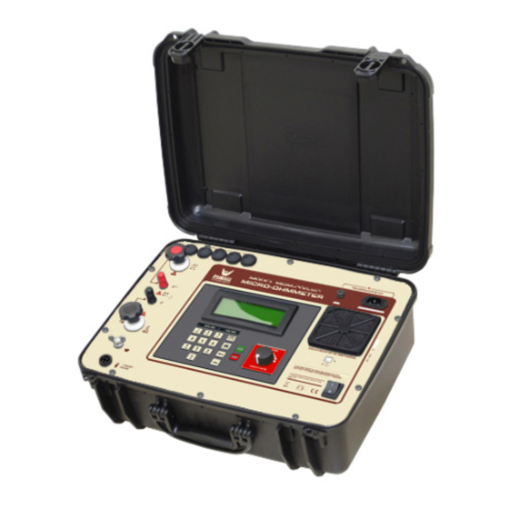
Page 7: Control Panel
„ Control panel Air exit Fuse Display Power cord connector Current terminal (C+) Cooling system Potential terminal (P+) Keyboard Potential terminal (P-) USB connector Current terminal (C-) Test current control Ground On/Off switch Auxiliary current clamp connector v210101... -
Page 8: Display
Display Alphanumeric LCD display where the measurement result, the corresponding measuring unit, the elapsed time since the measurement started and messages to the operator are displayed. „ Built-in chronometer It features the elapsed time (in minutes and seconds) since test current is applied. „... -
Page 9: Display Messages
„ Display messages The equipment is carrying out some functional veri昀椀cations. Main screen where a test can be started, or set a new one. Indicates that the test current is not enough to carry out the reading. Indicates that the measured resistance is higher than the maximum value readable. -
Page 10: Settings And Adjustments
Settings and adjustments This equipment has a MENU for settings and adjustments. To access the MENU, press the Selector / Adjust ( ), or press button. All navigation is performed through the and all panel keys are disabled, with the exception of the key that has the function to cancel and return to the initial screen. - Page 11 MENU SUB-MENU DESCRIPTION EDIT OBJECT NAME Allows write the name of the object under test, using the alphanumeric keyboard. TEST MODE Allows to select the test mode: MANUAL or AUTOMATIC. TEST CURRENT Allows to select the test current for Automatic Mode. SETUP TEST TEST DURATION Allows to setup the test duration between Unlimited (with-...
-
Page 12: Operating The Equipment
Operating the equipment z The User guide and its respective safety precautions must be read and understood before using the micro-ohmmeter z The usual safety precautions and safety regulations must be strictly observed z It should be checked that the item to be measured is voltage free z To ensure safety, use only the accessories supplied by the manufacturer Before turning the equipment On, connect the test leads to the item to be measured and to the front panel terminals. - Page 13 Measurement with potential risk Ex .: High voltage circuit breaker under external in昀氀uence of electromagnetic 昀椀elds from nearby energized devices. The safety ground terminal must be connected before making the other connections to the equipment. v210101...
- Page 14 Turn on the device with the On / O昀昀 key ( The display of the equipment will show the presentation message MRM-200-V2. The AUTO CHECK message will appear next and then the main screen. Access the device’s MENU using the key.
-
Page 15: Manual Mode
11. The unit of measured resistance shall be expressed in Ω (ohms), mΩ (mili-ohms) or μΩ (micro-ohms). 12. This information can be saved in the internal memory during and / or after the test simply by pressing the key. 13. To 昀椀nish the test, press the red key. -
Page 16: Auto Mode
„ Auto mode In auto mode, the operator preselects the current value before the test (the preselected value cannot be changed during the test). Access the device’s MENU pressing the button. to con昀椀rm. Select SETUP TEST and press to con昀椀rm. Select TEST MODE and press to con昀椀rm. -
Page 17: Both Side Ground (Bsg)
Both Side Ground (BSG) The BSG (Both Side Grounded) test mode provides to the user and to the equipment a safer way to test objects in a substation since the both sides of a switch, contact or circuit breaker is maintained connected to the ground during the whole test. ATTENTION: To perform this procedure, place the auxiliary current clamp on the ground of the test object before turning on the equipment Access the device’s MENU pressing the... -
Page 18: Protections
Protections The MRM-200-V2 continuous using time is limited by thermal considerations. Some internal sensors measures the temperature of the sensitive parts and trigger the protection that will stop the current generation if any of them exceeds the limit temperature, thus avoiding any damage. The OVERHEATING message will appear in the display. -
Page 19: Cooling System
Cooling system The MRM-200-V2 has a cooling system that allows it to perform a large number of consecutive tests without activating the thermal protection. Under normal environmental conditions you can perform up to 30 consecutive tests with duration of 1 minute and 1 minute interval. -
Page 20: Internal Memory
Internal memory The internal memory can store up to 4000 readings, organized by records. Each record works like a folder where all readings saved will be stored in until the operator creates another folder (record). During a measurement, when you want to save a measured value, press the key. -
Page 21: Desktop Software
Desktop software The PXLogger software makes communication between the equipment and a computer with Windows operative system easier. It makes possible to: z Synchronize the date and time of the equipment internal clock with the computer date and clock z Transfer the stored data z Clear the internal memory z Generate tests reports, etc USB drivers... -
Page 22: Android Software
Android software The PHENIX equipment that have Bluetooth interface can be controlled remotely via an Android device running PHENIX Remote Control app. „ Minimum requirements z Android 4.4 KITKAT System or higher z Bluetooth Communication „ Pairing To perform the pairing between equipment and Android device, follow the procedure: z To enable the Bluetooth, in screen “Applications”, tap “Settings”... -
Page 23: Maintenance
Maintenance Before each use, check the equipment for visible damage to the enclosure, panel, cables and accessories. If any malfunction or damage is found that could compromise the safety of the equipment, do not use it and contact the Service Center. „... -
Page 24: Fuse Replacement
„ Fuse replacement PRECAUTIONS z Perform the procedures below with the equipment turned o昀昀 z Disconnect the equipment from the mains supply and remove the power cord z Disconnect the test leads Fuse speci昀椀cations: Fuse Schurter Model SPT 5 x 20 mm, Time-lag T, 10 A / 250 V~ High breaking capacity Disconnect the equipment from the mains, unplugging the power cord. -
Page 25: Technical Speci昀椀Cations
Technical speci昀椀cations ELECTRICAL From 5 A up to 200 A (True DC) Test current The test current can be adjusted in: • Steps of 0.2 A from 5 A to 20 A • Steps of 1 A from 20 A to 200 A 0.1 μΩ... - Page 26 SOFTWARE PXLogger software: to transfer stored data in the equipment’s Desktop (PC/Notebook) memory, analyze it and generate test reports PHENIX Remote Control app: for remote control, allowing to Android (Smartphone/Tablet) configure, run tests and generate reports ENVIRONMENTAL IP54 (with closed lid) IP rating 0 °C to 50 °C...
- Page 27 NOTES v210101...
- Page 28 v210101...
Need help?
Do you have a question about the MRM-200-V2 and is the answer not in the manual?
Questions and answers