
Subscribe to Our Youtube Channel
Related Manuals for Kistler 5612A Series


Summary of Contents for Kistler 5612A Series
- Page 1 Instruction Manual MSW DTI sensors Measurement steering wheels Type 5612A... 5612A_002-861e-03.19...
- Page 2 Instruction Manual MSW DTI sensors Measurement steering wheels Type 5612A... 5612A_002-861e-03.19...
- Page 4 © 2019 Kistler Group. Kistler Group products are protected by various intellectual property rights. For more details visit www.kistler.com. The Kistler Group includes Kistler Hold- ing AG and all its subsidiaries in Europe, Asia, the Ameri- cas and Australia.
-
Page 5: Table Of Contents
MSW DTI sensors: Measurement steering wheels , Type 5612A... Inhaltsverzeichnis Introduction ..........................4 Important remarks ........................5 For your safety ........................5 Disposal information for electronic devices ................6 Software upgrades and updates ..................6 Product description ........................7 General ..........................7 Functional principle ......................8 3.2.1 Steering torque acquisition ..................8 3.2.2 Steering angle acquisition ..................8 3.2.3... - Page 6 KiCenter Software ........................20 Toolbar ..........................20 6.1.1 Explanation of the buttons in the toolbar .............21 Sensor settings MSW DTI ....................23 6.2.1 Sensor node ......................24 6.2.2 Measurement display ..................25 6.2.3 Sensor configuration ...................26 6.2.4 Digital outputs......................28 6.2.5 Analog outputs ....................30 6.2.6 CAN Bus ......................31 Firmware Update ......................34 Troubleshooting ........................36 Cables and power supply ....................36...
-
Page 7: Introduction
Where permitted by law, Kistler accepts no liability if this instruction manual is disregarded or if products other than those listed under accessories are used. -
Page 8: Important Remarks
2. Important remarks 2.1 For your safety Observe the following remarks before you commission the device. Kistler accepts no responsibility for damages that could arise from improper use of this product. Prerequisite for the proper and safe use of the device... -
Page 9: Disposal Information For Electronic Devices
Should it be necessary to use your own cables, always pay attention to the correct pin assignment. Kistler accepts no liability for damages caused by the use of cables other than those supplied by Kistler. For further information, please contact Kistler: +49 6441 9282 0 info.de@kistler.com... -
Page 10: Product Description
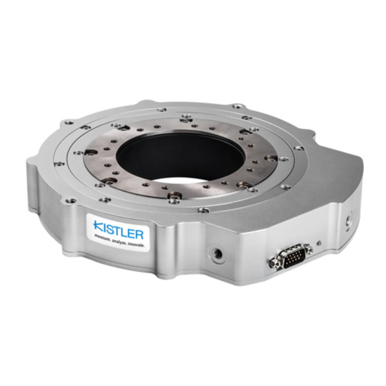
Product description 3. Product description 3.1 General The MSW DTI sensor is specifically designed to be used with modern steering wheels of passenger cars and utility vehicles and is applied for non-contact measurement of steering moment, steering angle and steering speed. The MSW DTI sensor offers high dynamics and excellent resolution without impairing steering wheel functions (air- bag) and control elements. -
Page 11: Functional Principle
MSW DTI sensors: Measurement steering wheels , Type 5612A... 3.2 Functional principle 3.2.1 Steering torque acquisition Torque values are acquired using a specially designed measuring body equipped with strain gauges. Friction and clearance of the integrated ball bearings do not influence the accuracy of the sensor. Torque applied to the steering wheel is transferred directly through the measuring body and into the steering shaft. -
Page 12: Features
ƒ Steering wheel adapter ø400 ... 560 mm 22001142 ƒ 1-point suction holder for mounting 18025571 at the windshield (car) ƒ 1-point suction holder for mounting 18029307 at the windshield (truck) ƒ Kistler angle lock adaptation,basic set 18026445 ƒ Transport case 55120723 ƒ Custom adaptations on request 5612A_002-861e-03.19... -
Page 13: Steering Angle Stop (Optional)
MSW DTI sensors: Measurement steering wheels , Type 5612A... 3.5.1 Steering angle stop (optional) Features of the steering angle stop: ƒ Fixes the steering angle to a pin point ƒ Enables steering movement between two different steering angles ƒ Easy handling ƒ... -
Page 14: Technische Daten
Technical data 4. Technical data 4.1 Specifications Performance specifications Power supply 10 ... 28 Power consumption at 12 V <20 Adjustable filter time 2 ... 512 (or unfiltered) Measurement frequency 1 000 Temperature ranges Nominal temperature range °C 0 ... 70 Operating temperature range °C –20 ... - Page 15 MSW DTI sensors: Measurement steering wheels , Type 5612A... Steering wheel adaptation Diameter of the hollow shaft ø mm Max. height of the measuring body Pitch circle for screw-on threads ø mm (M4/16 pcs) Signal outputs Analog outputs DA converter resolution Non-linearity ±16 Steering moment M1 (±50/250 N·m)
-
Page 16: Pin Assignments
Technical data 4.2 Pin assignments Fig. 3: MSW DTI electronics, connector view front plate Power, 8-pin LEMO, connector Signal Internal use Internal use Internal use Internal use Vin_EXT Vin_EXT GND_EXT GND_EXT CAN, 7-pin LEMO, socket Signal CAN high CAN low DGND DGND 5612A_002-861e-03.19... - Page 17 MSW DTI sensors: Measurement steering wheels , Type 5612A... USB/ETH, 7-pin Binder, socket Signal TX– RX– USB D+ USB D– DGND OUT, 14-pin. HD-Sub, socket Signal Ana_out 1 Ana_out 2 Ana_out 3 Ana_out 4 Ana_out 5 AGND Dig_out 1 Dig_out 2 Dig_out 3 Dig_out 4 DGND...
-
Page 18: Set-Up And Connection
Mounting of the steering shaft adapter and steering wheel must not generate or transfer mechanical stress or ten- sion to the housing area of the Kistler MSW. Make sure that you have the correct screw length, strength class and tightening torque (see chapter 5.3). -
Page 19: Sensor Sketch
MSW DTI sensors: Measurement steering wheels , Type 5612A... When returning a measurement steering wheel for calibration to Kistler, it should be the original extent of delivery to ensure that service will run smoothly. Improper operation invalidates the warranty. Improper, unauthorized modifications irretrievably change the calibration! 5.3 Sensor sketch... -
Page 20: Mounting The Sensor In The Vehicle
Set-up and connection 5.4 Mounting the sensor in the vehicle 5.4.1 Sensor with standard steering wheel and standard steering shaft adapter Essentially, mounting the measuring steering wheel corre- sponds to mounting an original equipment steering wheel. ƒ Remove the original steering wheel according to the manufacturer’s instructions. -
Page 21: Connecting The Sensor
MSW DTI sensors: Measurement steering wheels , Type 5612A... 5.5 Connecting the sensor Fig. 5: MSW DTI electronics, connector view front plate 5.5.1 For configuration ƒ Take the sensor cable and connect the signal output of the MSW DTI sensor to the signal input on the electronics. -
Page 22: Start-Up
Set-up and connection The CAN bus of the MSW DTI electronics is equipped with a 120 Ω termination resistor! Switch the resis t or on/ off via KiCenter. ƒ Connect the electronics to a suitable power distribu- tion unit using the power/DTI cable. When the MSW DTI sensor is connected to a DTI-Logger, the sensor is powered by the DTI-Logger. -
Page 23: Kicenter Software
MSW DTI sensors: Measurement steering wheels , Type 5612A... 6. KiCenter Software 6.1 Toolbar The toolbar is divided into three categories ƒ Database Operations ƒ Connection ƒ Tools Fig. 6: Device Center, 1 Page 20 5612A_002-861e-03.19... -
Page 24: Explanation Of The Buttons In The Toolbar
KiCenter Software 6.1.1 Explanation of the buttons in the toolbar 1. Database operations Transferring the current settings from KiCenter to the device. Reads the current settings from the device. Changes that were made in KiCenter but were not then transferred to the device are lost in the process. Importing device parameters from a file (*kdx). - Page 25 MSW DTI sensors: Measurement steering wheels , Type 5612A... Config serial All devices that have only USB or USB and RS-232C on the front panel, regardless of the connection used (USB or RS-232C). Config net All devices that have a network port on the front pa- nel, regardless of the connection used (LAN or USB).
-
Page 26: Sensor Settings Msw Dti
The KiCenter software is needed to configure and cali- brate the sensor. The software can be found on the included USB stick or at www.kistler.com. To connect the sensor to KiCenter, it must be connected to the computer using either the USB connecting cable or a LAN cable. -
Page 27: Sensor Node
MSW DTI sensors: Measurement steering wheels , Type 5612A... 6.2.1 Sensor node If the MSW DTI sensor (serial number) node is selected, the status page appears in the work area. Displayed here are the most important pieces of information and settings for the connected MSW DTI sensor. -
Page 28: Measurement Display
KiCenter Software 6.2.2 Measurement display On the “Measurement Display” page, the current measurement values of the MSW DTI sensor are displayed. This is used to monitor the function of the sensor. If no or implausible values are received on a given signal output, the measurement display can be used to perform a comparison. -
Page 29: Sensor Configuration
MSW DTI sensors: Measurement steering wheels , Type 5612A... 6.2.3 Sensor configuration Various options for the use of the sensor can be set on the “Sensor Configuration” page. Fig. 9: Screen view „Sensor Configuration” 1. Settings Filter activate Activation of a moving average filter that is applied to all output signals. The larger the filter time, the more strongly the signals are smoothed, but the longer the signal delay. Signal delay Display of the current signal delay, consisting of processor computing time and delay caused by the filter. - Page 30 KiCenter Software Mounting Normal / Reverse With normal mounting – the steering wheel end (screw side) points upwards –, the bearing friction is not measured. If the bearing friction shall be measured, the sensor element must be mounted in reverse – the steering wheel end (screw side) points downwards.
-
Page 31: Digital Outputs
MSW DTI sensors: Measurement steering wheels , Type 5612A... 6.2.4 Digital outputs On the “Digital Output” page, the resolution and the center frequency of the digital output can be set. Fig. 10: Screen view „Digital Output” Basic settings Digital channel Signal Steering Steering... - Page 32 KiCenter Software With the digital channels 1 and 2, a center frequency is determined to enable negative values for the signals steering moment and steering angle. Example: steering moment, resolution 100 Hz/km/h, center frequency 6 000 Hz –5 km/h → 4 500 Hz 0 km/h → 5 000 Hz 5 km/h → 5 500 Hz Digital channel 4 outputs the same as digital channel 3, but phase-shifted by 90°.
-
Page 33: Analog Outputs
MSW DTI sensors: Measurement steering wheels , Type 5612A... 6.2.5 Analog outputs The output for the analog channels can be configured on the “Analog Output” page. The desired resolution and offset can be set here. Fig. 11: Screen view „Analog Output” Basis settings The steering moment (M1, M2), steering angle (L1, L2) and steering speed signals are permanently assigned to... -
Page 34: Can Bus
KiCenter Software 6.2.6 CAN Bus The settings for the CAN bus can be adjusted on the “CAN Bus” page. Fig. 12: Screen view “CAN Bus” 1. CAN settings Baud rate Presetting: 1 MBaud Transmission speed of the CAN bus protocol. Must match the settings in the data acquisition system. - Page 35 MSW DTI sensors: Measurement steering wheels , Type 5612A... 2. Send modes Continuous send mode / send interval The data is transmitted continuously with the set interval time. The sensor always operates internally with an interval time of 1 ms. If you increase the transmission interval, not every measured value is output via the CAN bus.
- Page 36 KiCenter Software 4. Creating a CAN DB It is possible to generate CAN database files (CAN DB) using the KiCenter software. A CAN DB can only be created on the status page. To begin generating a CAN DB, click on the “Create CAN DB”...
-
Page 37: Firmware Update
MSW DTI sensors: Measurement steering wheels , Type 5612A... 6.3 Firmware Update Because the sensors are constantly being developed further, it may be necessary to update the firmware. This chapter describes how to do this using KiCenter. Before performing a firmware update, ensure that the data connection between the PC and the sensor, as well as the power supplies to the PC and the sensor, are correct. Interruptions to the communication link, the power supply to the sensor, or a computer crash during the update can cause irreparable damage to the sensor programming. - Page 38 KiCenter Software Fig. 15: Screen view “Firmware Update”, Step Please make sure that both are correct and then confirm this message by clicking on “OK”. Step 2: Select the firmware file Next, you are prompted to select the firmware file (*.fwu) that you would like to write to the sensor. Click on “Open” to confirm the file; loading of the new firmware begins. From this time on, the firmware update must not be interrupted! The firmware update ends automatically.
-
Page 39: Troubleshooting
MSW DTI sensors: Measurement steering wheels , Type 5612A... 7. Troubleshooting 7.1 Cables and power supply ƒ Check whether all plug and receptacle connectors are correct and the system is connected to an appropriately dimensioned power supply. ƒ Check whether the correct cables were used. ƒ... -
Page 40: Emc Interference
12 months. With the MSW DTI sensor, you have purchased a high- quality and high-precision measuring instrument. We recommend that you send the device to Kistler once per year for inspection, maintenance and calibration. 5612A_002-861e-03.19 Page 37... -
Page 41: Appendix
MSW DTI sensors: Measurement steering wheels , Type 5612A... 8. Appendix A. Dimensions 1. Sensor element Page 38 5612A_002-861e-03.19... - Page 42 Appendix 2. Electronics 5612A_002-861e-03.19 Page 39...
- Page 43 MSW DTI sensors: Measurement steering wheels , Type 5612A... B. KiCenter/PC connection problems Always use the latest KiCenter version. You can find the current version at www.kistler.com. 1. Overview The following flowcharts show the possible paths for rectifying connection problems between KiCenter and PC. Flowchart 1: Begin troubleshooting Begin troubleshooting How is the device...
- Page 44 Does the device appear in Device Manager with an “!” before the name? (Section 3 auf Seite 45) Solution: Device driver missing! Please install the driver using the Hardware malfunction! alternative method (section 4 auf Please contact Kistler Support. Seite 47) 5612A_002-861e-03.19 Page 41...
- Page 45 MSW DTI sensors: Measurement steering wheels , Type 5612A... Flowchart 3: Ethernet troubleshooting Ethernet Troubleshooting Is DHCP activated in Don't know the device? Solution: Check the network settings of the device via USB! How is the device connected? Does the static address match the network? (Contact your system administrator for assistance.)
- Page 46 (KiCenter)” item visible in the firewall? (Section 6 auf Seite 53) Solution: Add KiCenter to Is the checkbox for “Public your firewall. Network” item checked? (Section 7 auf Seite 55) Solution: Give KiCenter the Please contact Kistler Support required permissions 5612A_002-861e-03.19 Page 43...
- Page 47 MSW DTI sensors: Measurement steering wheels , Type 5612A... 2. Is the device visible in the adapter settings? Open the Control Panel\Network and Internet\Network Connections. Find item “MFB2 Device” or “Kistler Device” here. Page 44 5612A_002-861e-03.19...
- Page 48 If the driver is correctly installed, MFB2 Device or Kistler Device is listed under item Network adapters. If no driver is installed, there is an “!” in front of the device name (MFB2 Device or Kistler Device) 5612A_002-861e-03.19 Page 45...
- Page 49 MSW DTI sensors: Measurement steering wheels , Type 5612A... In this case, install the correct driver as described in section 4 auf Seite 47. Page 46 5612A_002-861e-03.19...
- Page 50 If no driver is installed, a driver can be installed with the following steps: (Driver signature enforcement can also be deactivated under Win8.1.) 1. In Device Manager, go to Kistler Device and select “Update Driver Software…” Fig.: at1 2. On the next screen, click on “Browse my computer for browser software”.
- Page 51 MSW DTI sensors: Measurement steering wheels , Type 5612A... Fig.: at3 4. Select item Network Adapter. Fig.: at4 5. Remove the check mark for “Show compatible hardware”. Page 48 5612A_002-861e-03.19...
- Page 52 Appendix Fig.: at5 6. Navigate to “Microsoft” on the left side and “Remote NDIS Compatible Device” on the right side. Fig.: at6 7. Confirm the warning with “Yes” 5612A_002-861e-03.19 Page 49...
- Page 53 MSW DTI sensors: Measurement steering wheels , Type 5612A... Fig.: at7 8. Click on close. The sensor can now be used. 5. Were the network address and the alternative network address automati- cally obtained from the PC? If yes, right click on the network connection (see figure below) and select Properties. Fig.: DE_Netzwerkeinstellungen.png Page 50 5612A_002-861e-03.19...
- Page 54 Appendix The following screen view appears: Fig.: DE_Netzwerkeinstellungen2 Select Internet Protocol Version 4 (TCP/IPv4) and click on “Properties” The following screen view appears: Fig.: DE_Netzwerkeinstellungen3 5612A_002-861e-03.19 Page 51...
- Page 55 MSW DTI sensors: Measurement steering wheels , Type 5612A... Make certain that “Obtain IP address automatically” is activated. Click on Alternative configuration... Fig.: DE_Netzwerkeinstellungen4 ... and make certain that “Automatically assigned, private IP address” is active. Page 52 5612A_002-861e-03.19...
- Page 56 Appendix 6. Firewall settings If a network connection is established via USB RNDIS or Ethernet but no connection can be established, a firewall may be blocking the connection. The description refers to the Windows firewall. Other firewalls differ in appear- ance and operation. The functions should, however, be identical. Contact your system administrator in case of doubt. 1. Open the “Windows Firewall” element in the Control Panel. Fig.: DE_Firewall_App_zulassen Windows is a registered trademark of Microsoft Corporation.
- Page 57 MSW DTI sensors: Measurement steering wheels , Type 5612A... 2. “Allow a program or feature through Windows Firewall”. Fig.: DE_Firewall_allowed_Apps_public Check whether item “Configuration Software” is present in the list of allowed programs. 3. If “Configuration Software” is not present in the list, it can be added manually (see next chap- ter). 4. If the “Configuration Software” item is present, check that all network locations (domains) – private, public – are activated. If this is not the case, all network locations should be activated. Page 54 5612A_002-861e-03.19...
- Page 58 7. Adding KiCenter to the firewall In the lower right, click on “Allow another program (Another app)…”. If the field is not active, “Change settings” must first be clicked in the upper right to allow changes to be made. A list of programs appears. Fig.: DE_Firewall_allowed_Apps_add_KiCenter2 If the “Configuration Software” is not listed, click on “Search…” and search for file “KiCenter.exe”. The standard path is C:\Program Files (x86)\Kistler\KiCenter. 5612A_002-861e-03.19 Page 55...
- Page 59 MSW DTI sensors: Measurement steering wheels , Type 5612A... Fig.: DE_Firewall_allowed_Apps_add_KiCenter After clicking on “Open”, “Configuration Software” should appear in the list. Before the task is completed by clicking on “Add”, the settings should be checked under “Net- work (location) types …”. Fig.: DE_Firewall_allowed_Apps_add_KiCenter All entries should be activated.. Page 56 5612A_002-861e-03.19...
- Page 60 Appendix C. Declaration of conformity 5612A_002-861e-03.19 Page 57...
Need help?
Do you have a question about the 5612A Series and is the answer not in the manual?
Questions and answers