
Subscribe to Our Youtube Channel
Related Manuals for Pixii Power Base 600


Summary of Contents for Pixii Power Base 600
- Page 1 Installation Guide Power Base 600 Grid tied energy storage system Document number: 14735, rev. 1.0 Issue date: 08.06.2022...
- Page 2 Commissioning and configuration of equipment should be done only by Pixii personnel or by other authorized and qualified persons. For safety reason, before you start installation, ensure all external power sources are disconnected, as well as internal battery and load fuses/breakers.
- Page 3 Wear appropriate personal protective equipment when dealing with the battery module. • Remove watches, rings, or other metal objects. • Use tools with insulated handles. • Wear rubber gloves and boots. The battery module is heavy enough to cause severe injury. Installation Guide ● Power Base 600...
- Page 4 If the battery catches fire, it will produce noxious and poisonous gases. Do not approach. Wet batteries If the battery module is wet or submerged in water, do not try to access it. Contact Pixii or your distributor for technical assistance.
- Page 5 No part of this document may be reproduced, copied or transmitted (electronic or mechanic, including photocopying and recording) for any purpose to 3 party without the explicit written permission of Pixii. Copyright © Pixii 2022 ...
-
Page 6: Table Of Contents
4.11 Customer MODBUS connection RS485 ........39 Installation Guide ● Power Base 600... - Page 7 6.3 Air condition unit ........... . . 46 Installation Guide ● Power Base 600...
-
Page 8: Introduction
Input Connector 4x50-240 (PE, N) 45Nm Input Connector 4x95-240 (L1, L2, L3) 50Nm Polarium batteries (DC cables) 15,0Nm Terminal block (WDK2.5) 0,4-0,6Nm Teminal block (DLD 2.5) 0,4-0,6Nm Relay socket 0,5Nm 9,8Nm 47,0Nm Table 2. Recommended torques Installation Guide ● Power Base 600... -
Page 9: Description
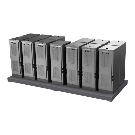
1x PWM Power Master Cabinet 11x PWS Power Slave Cabinet CC1 - CC5, CC7 - CC12 Front view Figure 1.1 Power system - front view Rear view Figure 1.2 Power system - rear view Installation Guide ● Power Base 600... -
Page 10: Thermal Management System (Tms)
It secures similar temperature around the batteries. Cabinet is equipped with 2x 500W AC powered heaters for lower temperature conditions securing adequate battery temperature. Side View Figure 1.3 Fan filter air flow diagram (side view) Installation Guide ● Power Base 600... -
Page 11: Air Conditioner With Heat Exchanger
Aircon is pre-set from factory to the temperature 23°C +/-5°C. If this setting is not acceptable for User manual HC Series Air conditions on site, set appropriate temperatures following instructions in the Conditioner with Heat Exchanger. Installation Guide ● Power Base 600... -
Page 12: Installation Block Diagram
Figure 1.5 Single line installation block diagram - behind the meter 1�4�2 In front of the meter Distribution grid MCCB Consumers Power Base Energy storage system Figure 1.6 Single line installation block diagram - in front of the meter Installation Guide ● Power Base 600... -
Page 13: System Ratings
Voltage fluctuations and flicker (for one system): Measured using Z 0,013Ω+j0,002Ω 0,645 0,603 test Maximum permissible network impedance, Z 0,093Ω+j0,093Ω Table 5. Voltage fluctuations and flicker * * Measurements above tested on a PowerShaper 50kW system. Installation Guide ● Power Base 600... -
Page 14: Environmental Specifications
Env. cat. (AS 4777.2:2020) Indoor, conditioned Outdoor** Table 6. Environmental specifications * Measurements above tested on a PowerShaper 50kW system. ** The Outdoor system rated up to only 50°C must be protected from solar radiation Installation Guide ● Power Base 600... -
Page 15: Mechanical Specifications
4450kg Weight (fully equipped, 3U batteries) 9850kg Weight (fully equipped, 4U 250Ah batteries) 10790kg Weight (fully equipped, 4U 300Ah batteries) 11750kg Table 7. Mechanical specifications - Power system 2438 6058 Figure 1.7 Mechanical specifications Installation Guide ● Power Base 600... - Page 16 Fan Filter Height 2106mm Width 706mm Depth 932mm Weight 200kg Table 8. Mechanical specifications - ACD cabinet Datum Jméno Nakreslen 3/30/2022 Peter Bino Zkontrolován Norma Figure 1.8 Fan Filter Cabinet dimensions Změny Stav Datum Jméno Installation Guide ● Power Base 600...
- Page 17 Table 9. Mechanical specifications - Power cabinets 1064 Datum Jméno Nakreslen Nakreslen 3/30/2022 Peter Bino Zkontrolov Zkontrolován Norma Norma Stav Změny Datum Jméno Stav Změny Datum Jméno Figure 1.9 Fan Filter Cabinet dimensions Figure 1.10 Air Condition Cabinet dimensions Installation Guide ● Power Base 600...
-
Page 18: Fuse List
Littelfuse Table 11. Fuse list for AC Distribution cabinet NOTE: Please consult replacement of any fuse or circuit breaker with Pixii first. 1�6 Anti-islanding The PowerShaper incorporates both passive and active anti-islanding functionality. The passive methods included are under/over voltage, under/over frequency and rate of change of frequency detection. The active anti-islanding functionality uses the frequency shift method based on feedback from frequency variation in combination with a small reactive power perturbation. -
Page 19: Preparing Installation Site
• Recommended tools list is in chapter “Recommended tools” on page 8. 3� Prepare AC Mains supply • Correct type of AC Mains supply (TN-S/TN-C) • Correct rating of AC input cables and external fuses • AC Mains supply meter Installation Guide ● Power Base 600... -
Page 20: Recommended Upstream Breaker And Input Cable
2 different types of meters. NOTE: Measured data are used at the customer's own risk. The distribution company or Pixii is not responsible for any losses resulting from its use, including losses due to errors or omissions in the data. -
Page 21: Industrial Grade Energy Meter
Preparing installation site 2�3�2 Industrial grade energy meter The Pixii system has support for an energy meters Phoenix Contact EEM-EM355 (external measuring transformers required) and EEM-EM357 (direct internal measuring up to 80A). Currently, communication via Modbus/RTU (RS485) is supported. This means that a cable (2-wire at least) needs to run from the meter to the controller in system. -
Page 22: Mechanical Installation
2892,5 Figure 3.1 Cable entries - bottom view 6058 5702 Date Date Designed by Checked by Approved by 10/26/2022 PeterBino Edition Sheet cable entries 1 / 1 6x resting points Resting points Figure 3.2 Installation Guide ● Power Base 600... -
Page 23: Lifting And Positioning
Appropriate traverse and container lifting hooks must be used for lifting� Do NOT use any other technique to lift the cabinet because of imminent damage� Do NOT lift cabinet with installed modules and batteries� Figure 3.3 Lifting and positioning Installation Guide ● Power Base 600... -
Page 24: Unpacking
Place the structure on the floor and remove the tarpaulin from the system. • Figure 3.4 Removing the tarpaulin • Remove the foam top caps and other packing material from cabinets. Figure 3.5 Removing the foam caps Installation Guide ● Power Base 600... -
Page 25: Cabinets Preparation
Figure 3.10 Removing the bottom cover Figure 3.11 Removing the cable glands NOTE: Keep fixings and cover at safe place, as you need them later! NOTE: Connect antenna to the PWM cabinets only, other cabinets are antenna free. Installation Guide ● Power Base 600... -
Page 26: Removing The Humidity Stoppers
Outlet filter 1. Remove 8x M6 Nuts to release filter holders. 2. Remove humidity stopper. Figure 3.12 Humidity removal in outlet filter 3. Fix back all filter holders with 8x M6 Nuts from first step. Installation Guide ● Power Base 600... - Page 27 3. Fix back filter frame with 4x M6 Nuts from first step. NOTE: Gap between filter frame and the door plate is not a fault. Do NOT tighten screws too strong to reduce the gap. Installation Guide ● Power Base 600...
-
Page 28: Placing
Do NOT forget to open and secure the door on ACD cabinet. NOTE: Ensure, that input cables are NOT colliding with the equipment in the cabinet during the run down process. Figure 3.14 Placing of the structure Installation Guide ● Power Base 600... -
Page 29: Electrical Installation
4�1�1 Bottom cover Route cables through the openings in the bottom cover and fix the cover with 8xM6 torx screws from “3.4 Cabinets preparation” on page 25. chapter Installing the bottom cover Figure 4.2 Installation Guide ● Power Base 600... -
Page 30: Cable Glands
4�1�2 Cable glands Run cables through the cable glands, seal them and fix them to the ACD cabinet bottom cover with “3.4 Cabinets preparation” on page 25. screws from step Mounting the cable glands Figure 4.3 Installation Guide ● Power Base 600... -
Page 31: Protective Bonding
Route cable through the one of the cable glands on the bottom cover. NOTE: Do NOT interconnect bonding busbars in multiple cabinets in multicabinet installation. Connect separate bonding cable to each cabinet in multicabinet installation. Installation Guide ● Power Base 600... -
Page 32: Ac Mains Connection
Figure 4.5 AC mains cable - TN-S (230/400Vac) NOTE: Number of input cables may differ. Max. number of input cables, capable to install to the input breaker is 4 pieces. Installation steps are same for all cables. Installation Guide ● Power Base 600... -
Page 33: Tn-C-S (230/400Vac)
Conductor (CU, AL) 95mm - 240mm Figure 4.6 AC mains cable - TN-C-S (230/400Vac) NOTE: Number of input cables may differ. Max. number of input cables, capable to install to the input breaker is 4 pieces. Installation Guide ● Power Base 600... -
Page 34: Emergency Disconnect Switch
Figure 4.8 Emergency disconnect switch terminals (alternative position) 4�5 System label Pixii cabinets are marked with 2 system labels. One label is located on the outside of the cabinet (top right part of the cabinet), and one is located inside each cabinet on the cabinet door. -
Page 35: Customer Alarm Connection
Power Base system. All relays are configurable through the software. It could be added different alarm/warning to each of them. All relays contacts are accessible on connector terminals -X25. Figure 4.10 Customer alarm connector terminals Installation Guide ● Power Base 600... -
Page 36: Separate Alarm
Cab. 2 Cab. x Customer alarm box Figure 4.12 Common alarm (Serial) Alternative 2 (Parallel connection NO-C) . . . Cab. 1 Cab. 2 Cab. x Customer alarm box Figure 4.13 Common alarm (Parallel) Installation Guide ● Power Base 600... -
Page 37: Customer 230V
Electrical installation 4�7 Customer 230V Pixii system contains 230V terminals -X:23, for customer equipment (AC socket, ...), located on the top right of the cabinet. Connect PE wire to the terminal -X23:6, phase wire to the terminal -X23:2 and neutral wire to the terminal -X23:4. -
Page 38: Router Connection
Figure 4.16 Network cable connection (alternative position) 4�9 Customer space On the top of the ACD cabinet is located 10U space for installation of customer equipment. Cabling are accessible through the rear right corner. Figure 4.17 Customer space Installation Guide ● Power Base 600... -
Page 39: Ac Meter Connection
On the top right side of the ACD cabinet are located terminals for MODBUS connection -X28. Insert and fix: • connector B to the terminal -X28:2 • connector A to the terminal -X28:4 • connector GND to the terminal -X28:6 Figure 4.19 Customer MODBUS connection terminals -X28 Installation Guide ● Power Base 600... -
Page 40: Thermostat
Thermostat is located on the top of the door and is preset from factory to 35°C. Temperature can be adjusted using cog-wheel under the dial. Figure 4.20 Thermostat 4�13 Finalization “4.1 Preparation” on After successful installation, mount plastic cover back following steps in chapter page 29. Installation Guide ● Power Base 600... -
Page 41: Installing Batteries
187mm 148mm Figure 4.21 3U battery option Figure 4.22 4U battery option NOTE: Figure 4.23. Flip battery mounting brackets (ears) when using 4U batteries. See picture Figure 4.23 Flipped mounting brackets on 4U battery Installation Guide ● Power Base 600... - Page 42 (depending on the accessible holes on the mounting brackets) self tapping screws (see using torque T5. Figure 4.24 Battery positions Figure 4.25 Battery installation NOTE: Empty battery positions, if any, must be covered by blank panels to obtain correct air flow inside the cabinet. Installation Guide ● Power Base 600...
-
Page 43: Battery Connection
Insert termination plug to the last unused Modbus port. See details in Figure 4.26 NOTE: Ensure, that battery cables are not in/not colliding with air gap between the batteries. It could cause overheating problems. Installation Guide ● Power Base 600... -
Page 44: Battery Com Converter
Proper configuration of converter (-TF2) is necessary to secure the correct communication with various type of batteries. Follow the tables below to set the DIP switches in the right positions. Figure 4.28 Battery Com converter (-TF2) Polarium batteries configuration Shoto batteries configuration table table Installation Guide ● Power Base 600... -
Page 45: Power Modules
WARNING: Do NOT touch connectors on the module rear side, there is risk of electric shock because of accumulated energy inside. NOTE: Empty positions must be covered with blank panels to obtain correct airflow. Installation Guide ● Power Base 600... -
Page 46: Commissioning Procedure
Do not limit the evaluation to only those points. NOTE: For repair and replacement use only original Pixii parts and in accordance with technical specification provided by Pixii. Use of non-original parts may void the warranty provided by Pixii. - Page 47 Maintenance Installation Guide ● Power Base 600...
Need help?
Do you have a question about the Power Base 600 and is the answer not in the manual?
Questions and answers