
Subscribe to Our Youtube Channel
Related Manuals for RTA 460AAWS-NNA1


Summary of Contents for RTA 460AAWS-NNA1
- Page 1 460AAWS-NNA1 Protocol Gateway Product User Guide Firmware Version 8.8.22 Real Time Automation, Inc. 1-800-249-1612...
- Page 2 Trademarks CompactLogix, ControlLogix, & PLC-5 are registered trademarks of Rockwell Automation, Inc. EtherNet/IP is a trademark of the ODVA. MicroLogix, RSLogix 500, and SLC are trademarks of Rockwell Automation, Inc. Microsoft, Windows, and Internet Explorer are registered ® trademarks of Microsoft Corporation. BACnet is a registered trademark of American Society of Heating, Refrigerating and Air-Conditioning Engineers (ASHRAE).
-
Page 3: Table Of Contents
Revision History ............................6 Overview ............................... 8 Hardware Platforms ............................9 Hardware – NNA1 ........................... 10 Powering the Gateway ..........................10 Port Configuration ........................... 11 RS232 pinouts: ............................11 RS485 pinouts: ............................11 TTL pinouts: ............................. 12 Mounting with a DIN Rail ..........................13 Installing .............................. - Page 4 Certificate setup ..........................44 Attach policies to certificate ....................... 46 Testing AWS Communication ........................50 Send data from AWS to RTA gateway (Subscribe Topic) ..............51 Send data from RTA gateway to AWS (Publish Topics) ..............52 QT Publish Trigger ............................55 Mapping - Transferring Data Between Devices ..................
- Page 5 Change of State (COS) Configuration ......................84 Diagnostics Info ............................85 Diagnostics Mapping ..........................85 Diagnostics – ASCII ............................86 Diagnostic – MQTT Client ..........................91 LED Configuration ............................93 Configuration Files ............................94 Export Configuration ..........................94 Import Configuration ..........................94 Save and Replace Configuration Using SD Card ..................
-
Page 6: Revision History
Revision History Version Date Notes 8.4.5 11/18/2019 Features Added 1. Released OPC UA Server (US) Protocol 2. Ability to now Import/Export Template Files with out an FTP session Bug Fixes 3. Updated Profinet Server (PS) on N34 hardware Platform 4. Updated Wi-Fi software 2/28/20 8.6.0 Bug Fixes... - Page 7 Version Date Notes 8.9.22 2/5/24 Features Added: 1. Added priority-based reads for client protocols 2. Added improved diagnostic timers for client protocols 3. Reduced minimum delay between messages to zero ms on client protocols 4. Added support for USB serial connections 5.
-
Page 8: Overview
Overview The 460AAWS-NNA1 gateway Interface serial ASCII devices with Amazon Web Services (AWS) IoT Core. By following this guide, you will be able to configure the 460AAWS-NNA1 gateway. Number of ASCII devices is dependent on the Hardware and Product number of the 460 gateway. -
Page 9: Hardware Platforms
Hardware Platforms The 460 Product Line supports a number of different hardware platforms. There are differences in how they are powered, what serial settings are supported, and some diagnostic features supported (such as LEDs). For these sections, be sure to identify the hardware platform you are using. To find which hardware platform you are using: 1) Look on the front or back label of the unit for the part number. -
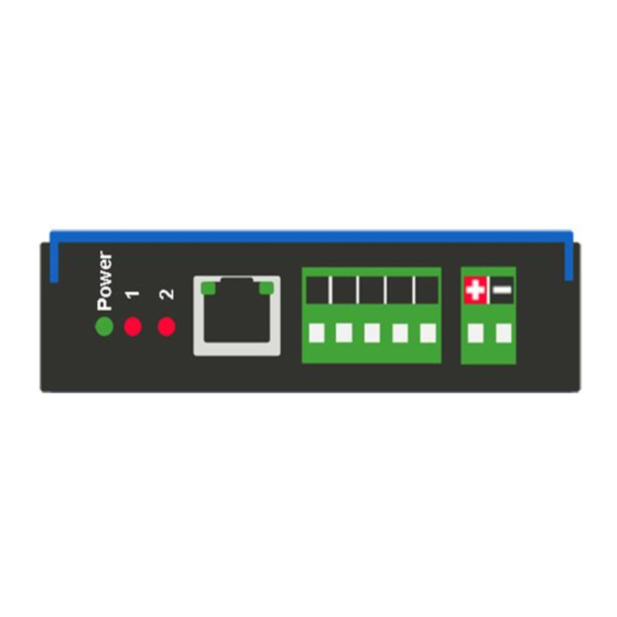
Page 10: Hardware - Nna1
Hardware – NNA1 Powering the Gateway 1) Connect a 12-24 VDC power source to the gateway, Red Wire = (+) Black Wire = (-). a) The unit draws 175mA @ 12 V. Real Time Automation, Inc. 1-800-249-1612... -
Page 11: Port Configuration
Port Configuration The Port Configuration page is where you set port specific parameters. These settings must match the settings of the device(s) that you are connecting to. Only 1 mode can be configured for this hardware. Below are the wiring pinouts for each mode. When you have completed your port configuration, click the Save Parameters button. -
Page 12: Ttl Pinouts
TTL pinouts: Real Time Automation, Inc. 1-800-249-1612... -
Page 13: Mounting With A Din Rail
1) Mount your DIN Rail. 2) Hook the bottom mounting flange under the DIN Rail. 3) While pressing the 460AAWS-NNA1 against the rail, press up to engage the spring loaded lower clip and rotate the unit parallel to the DIN Rail. -
Page 14: Accessing The Main Page
Accessing the Main Page The following steps will help you access the browser based configuration of the gateway. By default, DHCP is enabled. If the gateway fails to obtain an IP address over DHCP it will Auto IP with 169.254.X.Y. For more information on your Operating system network setting refer to the Accessing Browser Configuration... - Page 15 Error: Main Page Does Not Launch If the Main Page does not launch, please verify the following: 1) Check that the PC is set for a valid IP Address a. Open a MS-DOS Command Prompt b. Type “ipconfig” and press enter c.
-
Page 16: Committing Changes To The Settings
Committing Changes to the Settings All changes made to the settings of the gateway in Configuration Mode will not take effect until the gateway is restarted via the webpage. Changes will not be stored if the gateway’s power is removed prior to a reboot. -
Page 17: Main Page
Main Page The main page is where important information about your gateway and its connections are displayed. Mode (orange box below): Running Mode: • Protocol communications are enabled • Configuration cannot be changed during Running Mode. If changes are needed, click the Configuration Mode button shown in the green box below... -
Page 18: Device Configuration
Device Configuration The device configuration area is where you assign the device description parameter. Changes can only be made when the gateway is in Configuration Mode. Once you are done configuring the Description, click the Save Parameters button. Real Time Automation, Inc. 1-800-249-1612... -
Page 19: Network Configuration
Network Configuration The network configuration area is where you assign the IP address and other network parameters. Changes can only be made when the gateway is in Configuration Mode. Once you are done configuring the Network Settings, click the Save Parameters button. If you are changing the IP Address of the gateway, the change will not take effect until the unit has been rebooted. -
Page 20: Ascii Configuration
ASCII Configuration After the port Configuration has been completed, click the ASCII button to continue configuration. 1) To add an ASCII device, or additional ASCII devices, click the -Select- dropdown menu under ASCII Configuration and select Add Generic ASCII option. a) To remove a device, navigate to the ASCII device to delete using the <<... -
Page 21: Receive Data
Receive Data This side is configured to receive data from the ASCII device into the gateway. Use the following fields to determine when a message has been received. 1) Enable: Check this box to configure the Receive Data section. 2) Max Message Length: Enter the max number of characters that can be received by the gateway. Example: Max Message Length is set to 5 and the message of "helloworld"... -
Page 22: Receive Data - Operation Mode
Bradley PLC. Next time the operator scans the same barcode “HelloWorld”. The ASCII side gathers the data, but the data didn’t change so it will not be sent over to the ETC portion of the RTA gateway. The operator scans “1234567890” with the barcode scanner. The ASCII side of the RTA gateway will process the data and since the data has changed it will be sent over to ETC and sent over to the PLC. -
Page 23: Transmit Data
Transmit Data This side is configured to transmit data from the gateway into the ASCII device. Use the following setup fields to help the 460 transmit an ASCII message. 1) Enable: Check this box to configure the Transmit Data section. 2) Max Message Length: Enter the max number of characters that can be transmitted by the gateway. -
Page 24: Transmit Data - Triggering Methods
Option 1: Change-Of-State is defaulted, so this method is chosen if the Transmit Timeout field is left at 0 and ALL data is new. Example 1: From the PLC, send a message of “hello”, through the RTA gateway the ASCII device see’s “hello”. Send “hello’ again, nothing will happen because of the RTA Change-of-State Rule. - Page 25 3000ms Timeout or the Trigger data point) the ASCII device will get updated. If the Trigger data point is not updated, the then the RTA gateway will send the data every x ms to the ASCII device. See below for more examples in the ASCII Configuration –...
-
Page 26: Ascii Configuration - Technology Triggering Method
ASCII Configuration – Technology Triggering Method This method allows the other protocol to signal when to send the next message using data handshakes. These “signals” are controlled using data variables (TransTrigger and TransHandshake) already in the mapping. This method will send the new/old data when triggered. NOTE: These two data variables will need to be mapped manually on the Data Mapping webpage since it will not be mapped using Auto-Map. - Page 27 If TransTrigger = 0, then the triggering method is enabled, but no message will transmit. RTA460 Display Data Example: TIA Portal Example: The data will still go to the RTA gateway, however the RTA gateway will NOT transmit the data to the ASCII device until the Slot12[0] triggers the TransTrigger.
-
Page 28: Ascii Configuration - Ascii Parsing
ASCII Configuration – ASCII Parsing The ASCII Parsing feature allows you to break apart an incoming ASCII string by delimiter or character offset into multiple data fields. You can then apply a data type to the fields and deliver them to user defined locations in the mating protocol. -
Page 29: Ascii Configuration - Ascii Parsing Examples
ASCII Configuration – ASCII Parsing Examples Example #1 - Parsing a message using the Parsing Delimiter option: In this example, we are separating the string “12.25,SP100,temp setpoint” by a comma delimiter. The first value is being parsed into a float data type, the second and third values are being parsed into a string data type. - Page 30 Example #3 - Parsing a message using the Parsing Delimiter option and Start Location and Length: In this example, we are separating the fields in the string “12.25,SP100,temp setpoint” using the comma delimiter, the start, and length fields. The first value is being parsed from the 1 character for a length of 2 and stored into an integer data type.
-
Page 31: Ascii Configuration - Ascii Concatenating
ASCII Configuration – ASCII Concatenating The ASCII Concatenating feature allows you to combine multiple data points and locations, in the mating protocol, into a single ASCII string. Click the ASCII Concatenating (Optional) button at the bottom of the ASCII Configuration page to access the ASCII Concatenating Configuration page for this device. 1) Number of Fields: This indicates how many values will be concatenated together to form a single ASCII message (up to 50 values per message). - Page 32 i. EX: 123.456789 set as %.3lf will display as 123.456 e. %e – used for Exponential Notation %x – used to represent Hexadecimal values for Signed/Unsigned Integers or Floating points g. String and Constant String Data Types do not use this field 6) Max Characters: This is the Max Number of Characters that can be transmitted for a single field.
-
Page 33: Ascii Configuration - Ascii Concatenating Examples
ASCII Configuration – ASCII Concatenating Examples Example #1 - Concatenating a message using the Concatenating Delimiter option: In this example, the comma is selected as the Concatenating Delimiter. Let’s look at each field closer: 1) Field 1 –8 bit int represented as Trans_Field01 in the gateway. It will output as an integer with a max of 10 characters. - Page 34 If the Transmit Data is set up with the following delimiters, then a sample result is pictured below: Example 1 Sample Result: This use case is sending data via 5 PLC tags. Using the Concatenating setup example and the Transmit example, the ASCII data will display within your ASCII device shown as the example below.
-
Page 35: Ascii Configuration - Ascii Message Counter
ASCII Configuration – ASCII Message Counter There is an additional ASCII variable that is very useful to access within the gateway’s mating protocol. This data variable will need to be added manually since it will not be mapped using Auto-Map. RecvCount- indicates how many ASCII messages have been successfully read by the gateway for that device. -
Page 36: Mqtt Client Configuration
Click the MQTT button to continue configuration. Amazon Web Services (AWS) Configuration You can only configure one AWS IoT Core connection with your RTA product. 1) To add an AWS connection, click the -Select- dropdown menu under MQTT Client Connection List and select Add Generic AWS Connection option. -
Page 37: Configuring Subscribe And Publish Topics
Within the RTA gateway configuration only enter in “aabb11224e9ex-ats.iot.us-east- 2.amazonaws.com” portion of the URL, everything else is ignored. 6) Enter the TCP Port for the MQTT broker to open a connection on. If this value doesn’t match, the gateway will not open a connection. -
Page 38: Additional Aws Requirements
4) The private key, certificate, and root certificate will need to be FTP’d into the RTA gateway’s Flash File System. 5) The time configuration will need to be set to the current date and time to establish a connection. -
Page 39: How To Ftp Files Into The Rta Gateway
How to FTP files into the RTA gateway 1) Save off the private key and certificate files to your desktop, keep these files in a secured location. 2) Within your Windows Task bar, right click and open a new Windows/File Explorer folder or go into your start menu and type File Explore. - Page 40 5) Navigate to the RTA gateway and on the left-hand side, click the OTHER -Select- dropdown and select Utilities. 6) Once on the Utilities page click the File List button. 7) Verify that your certification and private key files appear on this page.
-
Page 41: Aws Iot Core Service Setup
“Thing” and “Policies”. Before you can register your RTA gateway as a “thing,” we need to setup a “policy” for it. This policy will be assigned to our “thing” during the registration process and will grant it the permissions needed to access the MQTT topics that we will use to publish and subscribe messages. - Page 42 From the policy creation page, you add the statements that will dictate what connected devices are allowed to do. Assign a unique name to your policy and add four statements with the information listed below. Notice that when you type in the action, the field labeled “Resource ARN” will be automatically populated.
-
Page 43: Aws Iot Core Service Things Configuration
“Create things.” A new window will open with a number of things to create, chose “Create single thing” and click the Next button. If you have multiple RTA gateways, then you’ll need to select “Create many things”. Real Time Automation, Inc. -
Page 44: Certificate Setup
The next setting will be the “Specify thing properties”, here you will give your “Thing” a unique name and click the Next button at the bottom. Certificate setup Here you associate your “Thing” with the certificate that will be used to authenticate it with the AWS IoT Core service. - Page 45 Real Time Automation, Inc. 1-800-249-1612...
-
Page 46: Attach Policies To Certificate
“Download certificates and keys”. Download the certificate and the private key. Once downloaded, navigate back to this user guide section “how to FTP files into the RTA gateway” to load the certificate and private key into the gateway. Real Time Automation, Inc. - Page 47 Once you have successfully downloaded the files you will be redirected to the Things page. Within the Things page, click on the thing name you setup, in this example it would be RTA_Testing. From this page, you can view if the certificate is active and create a Device Shadow URL. Real Time Automation, Inc.
- Page 48 Along with the certificate and private key, your RTA product will need the Device Shadow URL. Click the Device Shadows tab and click “Create Shadow”. Enter in a Device Shadow name and click the Create button. You will be redirected to the Things page where you’ll see your new Device Shadow created.
- Page 49 Within the RTA gateway configuration Device Shadow URL, enter in “aabb11224e9ex-ats.iot.us-east- 2.amazonaws.com,” everything else is ignored. Real Time Automation, Inc. 1-800-249-1612...
-
Page 50: Testing Aws Communication
AWS, the two files have been FTP’d into the RTA gateway, and the Device Shadow URL is configured. Using the AWS MQTT test client, you can Subscribe to a topic (data from the RTA), and you can Publish to a topic (data to the RTA). -
Page 51: Send Data From Aws To Rta Gateway (Subscribe Topic)
Below is how the RTA AWS IoT Core Service is setup to Subscribe data from AWS to the RTA. Within AWS, click the “Publish to a topic” tab. Enter in the topic name that is defined in the RTA gateway “Subscribe Topics”... -
Page 52: Send Data From Rta Gateway To Aws (Publish Topics)
Navigate to the RTA Display data and refresh the web page. You will see your data being updated. Send data from RTA gateway to AWS (Publish Topics) This example shows a PLC writing data to the RTA gateway and presenting that data to the Publish topic. Real Time Automation, Inc. - Page 53 In the topic filter, use a wildcard character of “#” (subscribe to all topics), and click the Subscribe button. You’ll see the subscription once the new Publish data comes in. The “RTA” is the Client ID that is configured in the MQTT device configuration of the RTA. The “Data_From_RTA_2_AWS” is the Publish Topic name configured in the AWS device configuration page of the RTA.
- Page 54 Real Time Automation, Inc. 1-800-249-1612...
-
Page 55: Qt Publish Trigger
QT Publish Trigger By default, the RTA gateway will publish to the broker based on change of state. This means a new publish to the broker will occur any time a value changes. In an application where the client is being charged per publish, such as with AWS, this is not ideal. -
Page 56: Mapping - Transferring Data Between Devices
Mapping - Transferring Data Between Devices There are 5 ways to move data from one protocol to the other. You can combine any of the following options to customize your gateway as needed. Option 1 – Data Auto-Configure Mappings: The gateway will automatically take the data type (excluding strings) from one protocol and look for the same data type defined in the other protocol. -
Page 57: Display Mapping And Values
Display Mapping and Values The Display Data and Display String pages are where you can view the actual data for each mapping that is set up. Display Data Click the Display Data button to view how the data is mapped and what the values of each mapping are. Here you will see how each data point (excluding strings) is mapped. - Page 58 This page is very useful when verifying that all data is mapped somehow from one protocol to another. If a data point is not mapped, it will display on this page in a yellow highlighted box. The Display Data page will display up to 200 mappings per page, simply navigate to the next page for the additional mapping to display.
- Page 59 To view the actual data mappings, click the Edit Mapping button. For more details, see the Data Mapping-Explanation section. To view the data mappings purely as text, click the View as Text button. For more details, see the View Data Mapping as Text section. Real Time Automation, Inc.
-
Page 60: Display String
Display String Click the Display String button to view what the values of each Parsing and/or Concatenating strings are, you can also click on the Edit Mapping to view the mapping of each string. To view the source or destination groups from a string, click the dropdown menu to generate the information regarding that device. - Page 61 If there are values of “Data Not Valid “on this page, it indicates that the source has not been validated yet and no data is being sent to the destination. NOTE: You can view the whole string data by clicking on Diagnostics Info drop down and navigating to ASCII Diagnostics page.
-
Page 62: Display String Use Case
Display String use case Sending a message of “RTA,Support,Rocks” from an ASCII device to the RTA unit. The ASCII Parsing Configuration would look like my example below. There are more detailed examples of what all the fields represent in the ASCII Parsing section. -
Page 63: Data And String Mapping - Auto-Configure
Data and String Mapping – Auto-Configure The Auto-Configure function looks at both protocols and will map the data between the two protocols as best as it can so that all data is mapped. Inputs of like data types will map to outputs of the other protocols like data types first. -
Page 64: Data Mapping - Explanation
Data Mapping – Explanation Below are the different parts that can be modified to make up a data mapping. 1) Enable (red box above): Check to enable mapping. If not checked, this mapping is skipped. 2) Source Field (yellow box above): a) Group - Select the data group you set up in the protocol config to use for this mapping. -
Page 65: Data Mapping - Adding Diagnostic Information
The gateway operates at 200 ticks per second. This equates to one tick every 5ms. Thus, mapping this to a destination will give easy confirmation of data flow without involving one of the two protocols. If data stops on the destination end, then the RTA is offline. Real Time Automation, Inc. - Page 66 4) Heartbeat 100ms Update a) The Heartbeat 100ms Update variable can be used as a heartbeat that updates once every 100ms. The variable starts at 0 on gateway startup and increments by 1 every 100ms. This can be mapped into a destination on one of the available protocols to monitor the gateways connection status.
- Page 67 c) There are multiple ways to map the NetBmpStat. Option 1: Map the whole 32bit value to a destination. Example below shows the NetBmpStat is going to an Analog BACnet object. Using a connection of 5 Modbus Slave devices AI1 will show a value of 31.0000. Open a calculator with programmer mode and type in 31, this will represent bits 0 –...
- Page 68 7) Status_XY a) There are two Statuses provided, one for each protocol. This gives access to the overall status of that Protocol. Each Bit has its own meaning as follows: Common Status: 0x000000FF (bit 0-7)1 byte Hex: Bit Position: Decimal: Explanation: 0x00 if we are a Slave/Server...
- Page 69 Non-Recoverable Faults 0xFF000000 (bit 24-31)4 byte Hex: Bit Position: Decimal: Explanation: 0x01 16,777,216 nonrecoverable fault – task fatal err 0x02 33,554,432 nonrecoverable fault – config missing 0x04 67,108,864 nonrecoverable fault – bad hardware port 0x08 134,217,728 nonrecoverable fault – config err 0x10 268,435,456 Configuration Mode...
-
Page 70: String Mapping - Explanation
String Mapping – Explanation Below are the different parts that can be modified to make up a string mapping. String data types can only be mapped to other string data types. There is no manipulation that can be done on the string. 1) Enable (red box above): Check to enable mapping. -
Page 71: Mapping - Auto-Configure Mode To Manual Configure Mode
Mapping – Auto-Configure Mode to Manual Configure Mode To transition from Auto-Configure Mapping Mode to Manual Configure Mode, click the dropdown at the top of the Mapping Configuration page and select Manual Configure. After you click this button, you will be prompted to confirm if this is really what you want to do. Click OK to proceed to Manual Configure Mode or click Cancel to remain in Auto-Configure Mappings Mode. -
Page 72: Mapping - Manual Configure Mode To Auto-Configure Mode
Mapping – Manual Configure Mode to Auto-Configure Mode To transition from Manual Configure Mode to Auto-Configure Mapping Mode, click the dropdown menu at the top of the Mapping Configuration page and select Auto-Configure Mappings. Click OK to proceed to delete all current mappings and go back to Auto-Configure Mappings Mode. Click Cancel to keep all mappings and remain in Manual Configure Mode. -
Page 73: View As Text
View as Text Data Mapping The View as Text page displays the point to point mapping(s) you set up in the Data Mapping section. This will also display any manipulation(s) that are configured. Each line on this page will read as follows: ->... -
Page 74: Base Triggering - Data Validiation Triggering
Note: # is an internal reference to the Server/Slave number you are settings up. ex. RTA Server/Slave products can only be Trigger 1 and Handshake 1 since we are only 1 device. If RTA is a Master/Client, then you can have a Trigger# for each server/slave connected too. - Page 75 3) Within the Data Mapping page manually add 2 additional mappings. 4) The first mapping is going to be the Data Validation Triggering. AO21 will write to the RTA, MC Trigger 1 will mark data invalid. 5) The second mapping, the MC Handshake will increment that all data is validated and write to AI21 “all data is validated”.
-
Page 76: Security Configuration
Security Configuration To setup security on the 460 gateway, navigate to Other->Security Configuration. You can configure Security for 3 administrators, 5 users, and 1 guest. THIS IS A TOTAL SECURITY FEATURE The security feature offers a way to password protect access to diagnostics and configuration on the network. -
Page 77: Security Configuration-Security Levels
Security Configuration-Security Levels Each webpage in the gateway can have a separate security level associated with it for each user. Security Levels: 1) Full Access: Capability to view and configure a web page. 2) View Access: Capability to view a web page, but cannot configure parameters. 3) No Access: No capability of viewing the web page and page will be removed from Navigation. -
Page 78: Security - Log In
Security - Log In Username: Name of the user to login. Password: Password of the user to login. Log In: If login is successful, the user will be redirected to the Main Page. Send Password to Email: Sends the specified User’s Password to the email configured for that user. Display Hint: Displays the hint specified for the User if one was set up. -
Page 79: Email Configuration
Email Configuration To setup e-mails on the 460 gateway, navigate to Other->Email Configuration. You can configure up to 10 email addresses. 1) SMTP Mail Username: The email address that the SMTP server has set up to use. 2) SMTP Mail Password: If authentication is required, enter the SMTP Server’s password (Optional). 3) SMTP Server: Enter the Name of the SMTP Server or the IP Address of the Server. -
Page 80: Alarm Configuration
Alarm Configuration To setup alarms on the 460 gateway, navigate to Other->Alarm Configuration. 1) Alarm Delay upon Powerup: At Powerup, the gateway will have values of ‘0’ stored for all data. This may cause alarms to trigger before these values are updated by the mating protocols. Set this field to provide needed time to update fields before considering values for alarms. - Page 81 5) In the Clear Error Section: a. Select the Clear Error Operation. Available options are <, >, <=, >=, !=, ==, and Change of State (COS). This is the operation that will be used to compare the Data Point value against the Error Value to determine if the alarm needs to be cleared.
-
Page 82: Diagnostics - Alarm Status
Diagnostics – Alarm Status Alarm Status will only display under the Diagnostic menu tab if at least 1 Alarm is enabled. 1) # Alarms Enabled: This is a count of enabled alarms. 2) # Alarms Active: This is how many alarms are presently active (set). 3) Last Active Alarm: This is the last alarm that the gateway detected. -
Page 83: Alarms - Clear
Alarms – Clear When an alarm is cleared, the following will occur: 1) A one-time notification will be sent to the email associated with the alarm. a. For duplicate emails to occur, the alarm must become active and then be cleared again. 2) Total # Alarms Active will decrement. -
Page 84: Change Of State (Cos) Configuration
Change of State (COS) Configuration To access the configuration files in the 460 gateway, navigate to dropdown Other->COS Configuration. The gateway, by default only writes when data has changed. The gateway also waits to write any data to the destination until the source protocol is successfully connected. Default values should fit most applications. -
Page 85: Diagnostics Info
Diagnostics Info The Diagnostics page is where you can view both protocols’ diagnostics information, # of Data Mappings, # of String Mapping and # Alarm Mappings. For protocol specific diagnostic information, refer to the next few pages. Diagnostics Mapping This section displays the number of mappings that are enabled, Data Mapping and String Mapping will show the # of Errors and First Errors. -
Page 86: Diagnostics - Ascii
Diagnostics – ASCII Select ASCII in the top dropdown menu on the Diagnostics Page to view a breakdown of the diagnostics that are displayed on the page. You may also view individual ASCII device counters and messages by selecting the device in the All ASCII dropdown and clicking View. Additional diagnostic information can be found by clicking the Help button. - Page 87 Device Status - This will only display when viewing All ASCII. 1) Connected and Running– The gateway is connected to all the ASCII devices and data is being received/transmitted. 2) Not Connected – There have been no messages received or transmitted. a.
- Page 88 Variables - These are the values for All ASCII, or the ASCII device selected. 1) Successful Transmit Count: a) Number of messages that the gateway has transmitted to the ASCII device 2) Successful Receive Count: a) Number of complete messages that the gateway has received from the ASCII device 3) Received due to Length: a) Number of messages completed due to the Max Message Length being reached 4) Received due to Delimiters:...
- Page 89 4) Calculated Length of Data exceeds 255 Characters: Number of characters parsed within a field exceeds 255 characters Buffers Each buffer text area is divided into three separate parts. Refer to screenshot above for labels. 1) Starting byte for that line 2) HEX character representation 3) ASCII character representation (Unprintable ASCII characters (like <CR>) will be displayed as ‘.’...
- Page 90 Last Message Sent to ASCII: 1) Last message that the gateway sent to the ASCII device Note: The concatenated delimiters are not displayed in this message but will be transmitted with the message Send Data from Gateway to ASCII: (Used for testing only, Character limit of 1024): 1) Enter a message to send to your ASCII device 2) Can be used to test communication and test formatting of messages Real Time Automation, Inc.
-
Page 91: Diagnostic - Mqtt Client
Diagnostic – MQTT Client Select the MQTT Client in the dropdown menu on the Diagnostic page to view the breakdown of the diagnostics and common strings that are display on the page. You may also view the individual MQTT device counters by selecting the device in the All Devices drop down and clicking View. NOTE: This page will auto-refresh every five seconds. - Page 92 LED Status Solid Green (Connected): • The gateway is connected to all the MQTT devices that are configured and enabled Flashing Green (Not Connected): • No MQTT devices are configured / enabled. Go to the MQTT Client Device Configuration to configure a device Flashing Red (Not Connected): •...
-
Page 93: Led Configuration
LED Configuration To modify the behavior of the LEDs on the 460 gateway, navigate to Other->Setup LEDs. Each LED may be set to Disabled, Protocol 1, or Protocol 2. If either protocol is a master/client, you may set the LED to represent either all slaves/servers configured in the gateway or a slave/server device. To select a slave/server device: 1) Select the protocol in the left dropdown menu. -
Page 94: Configuration Files
Configuration Files To access the configuration file in the 460 gateway, select the dropdown Other->Export/Import Config. Export Configuration The Export Configuration allows you to save your configuration file for backup or to be imported into another gateway. This file is named rta_cfg.rtax by default. Upon clicking the Save Configuration to File button, you will be prompted to select a location to save the file. - Page 95 If it encountered an error while trying to load the saved configuration, the gateway will indicate the first error it found and a brief description about it under the Load Configuration button. Contact RTA Support with a screenshot of this error to further troubleshoot.
-
Page 96: Save And Replace Configuration Using Sd Card
Save and Replace Configuration Using SD Card Saving Configuration Using SD Card This function saves the gateway’s configuration automatically to an SD Card each time the gateway is rebooted via the Restart Now button on the web page. If this unit should fail in the future, the last configuration stored on the SD card and can be used for a new gateway to get the application back up and running quickly. -
Page 97: Intelligent Reset Button
Intelligent Reset Button If the IP Address of the gateway is forgotten or is unknown, there is an easy way to recover the IP Address using a reset button on the hardware. 1) On the side of the gateway with the SD card slot, there is a small pinhole. Using a paperclip, press the button through this pinhole and hold the button for at least 5 seconds. -
Page 98: Utilities
Utilities To access the Utilities page in the 460 gateway, navigate to Other->Utilities. The Utilities screen displays information about the gateway including Operation Time, File System Usage, Memory Usage, and Memory Block Usage. Here you can also: • View the full revision of the software. •...
Need help?
Do you have a question about the 460AAWS-NNA1 and is the answer not in the manual?
Questions and answers