Table of Contents
Advertisement
Revision G: 1712, Content updated.
Table of Contents
1.
2.
Part Names And Functions
3.
4.
5.
6.
7.
8.
9.
15. Solar Panel
WARNING
Installation MUST conform with local building codes or, in the absence of local codes, with the
National Electrical Code NFPA70/ANSI C1-1993 or current edition and Canadian Electrical
Code Part1 CSA C.22.1.
The information contained in the manual is intended for use by a qualified service technician
familiar with safety procedures and equipped with the proper tools and test instruments
Installation or repairs made by unqualified persons can result in hazards to you and others.
Failure to carefully read and follow all instructions in this manual can result in equipment
malfunction, property damage, personal injury and/or death.
This service is only for service engineer to use.
Light commercial MONO 3D Air
Conditioner
SERVICE MANUAL
Model Numbers:
Indoor Unit:
CTBU-09HWFN1-M(C); CCA3U-09HRFN1-M(C); CFAU-09HRFN1-M(C);
CTBU-12HWFN1-M(C); CCA3U-12HRFN1-M(C); CFAU-12HRFN1-M(C);
CTBU-18HWFN1-M(C); CCA3U-18HRFN1-M(C); MUEU-18HRFN1-M(C);
CTBU-24HWFN1-M(C); MCD-24HRFN1-M(C); MUEU-24HRFN1-M(C);
CTB-36HWFN1-M(C); MCD-36HRFN1-M(C); MUE-36HRFN1-M(C);
CTB-48HWFN1-M(C); MCD-48HRFN1-M(D); MUE-48HRFN1-M(C); MUE-60HRFN1-MW;
MTIU-09HWFN1-M, MTIU-12HWFN1-M; MTIU-18HWFN1-M; MTIU-24HWFN1-M;
MTI-36HWFN1-M; MTI-48HWFN1-M; MHG-60HWFN1-MW;
Outdoor Unit:
MOB30-09HFN1-MX0W; MOB01-09HFN1-MW0W; MOB30-12HFN1-MV0W;
MOB01-12HFN1-MV0W; MOCA30-18HFN1-MT0W; MOCA01-18HFN1-MT0W;
MOD30-24HFN1-MT0W; MOD01-23HFN1-MT0W; MOBA30-09HFN1-MT0W;
MOB30-12HFN1-MT0W; MOCA31-18HFN1-MT0W; MOD31-24HFN1-MT0W;
MOD30U-36HFN1-M; MOE30U-48HFN1-M; MOE30U-60HFN1-M
Mono DC
Advertisement
Table of Contents

Related Manuals for Eco Air CTBU-09HWFN1-M(C)


Summary of Contents for Eco Air CTBU-09HWFN1-M(C)
-
Page 1: Table Of Contents
Light commercial MONO 3D Air Conditioner Mono DC SERVICE MANUAL Revision G: 1712, Content updated. Model Numbers: Table of Contents Indoor Unit: Precaution CTBU-09HWFN1-M(C); CCA3U-09HRFN1-M(C); CFAU-09HRFN1-M(C); Part Names And Functions Dimension CTBU-12HWFN1-M(C); CCA3U-12HRFN1-M(C); CFAU-12HRFN1-M(C); CTBU-18HWFN1-M(C); CCA3U-18HRFN1-M(C); MUEU-18HRFN1-M(C); Service space CTBU-24HWFN1-M(C); MCD-24HRFN1-M(C); MUEU-24HRFN1-M(C); Refrigerant Cycle Diagram CTB-36HWFN1-M(C);... - Page 2 CONTENTS 1. Precaution ..............................1 1.1 Safety Precaution .......................... 1 1.2 Warning ............................1 2. Part Names and Features..........................4 2.1 Model Names of Indoor/Outdoor units ..................4 2.2 Part names of Indoor/Outdoor units ....................5 2.3 Features ............................10 3.
- Page 3 15.4 Operation Modes and Functions ..................... 103 16. Troubleshooting ............................. 109 16.1 Indoor Unit Error Display ......................110 16.2 Error Display on Two Way Communication Wired Controller ..........111 16.3 Outdoor unit error display ......................112 16.4 Diagnosis and Solution ......................116 16.5 Main parts check ........................
-
Page 4: Precaution
Be caution when unpacking and installing the product. 1. Precaution Sharp edges could cause injury, be especially careful of the case edges and the fins on the 1.1 Safety Precaution condenser and evaporator. For installation, always contact the ... - Page 5 If strange sounds or smoke comes Install the drain hose to ensure that from product, turn the breaker off or water is drained away properly. disconnect the power supply cable. A bad connection may cause water leakage. There is risk of electric shock or fire.
- Page 6 Do not insert hands or other objects through air inlet or outlet while the product is operated. Do not drink the water drained from the product. Use a firm stool or ladder when cleaning or maintaining the product. Be careful and avoid personal injury.
-
Page 7: Part Names And Features
2. Part Names and Features 2.1 Model Names of Indoor/Outdoor units Outdoor units Series Capacity Indoor units Cassette CCA3U-09HRFN1-M(C) MOB30-09HFN1-MX0W; A5 Duct CTBU-09HWFN1-M(C) MOB01-09HFN1-MW0W; Console CFAU-09HRFN1-M(C) MOBA30-09HFN1-MT0W A6 Duct MTIU-09HWFN1-M Cassette CCA3U-12HRFN1-M(C) MOB30-12HFN1-MV0W; A5 Duct CTBU-12HWFN1-M(C) MOB01-12HFN1-MV0W; Console CFAU-12HRFN1-M(C) MOB30-12HFN1-MT0W; A6 Duct MTIU-12HWFN1-M Cassette... -
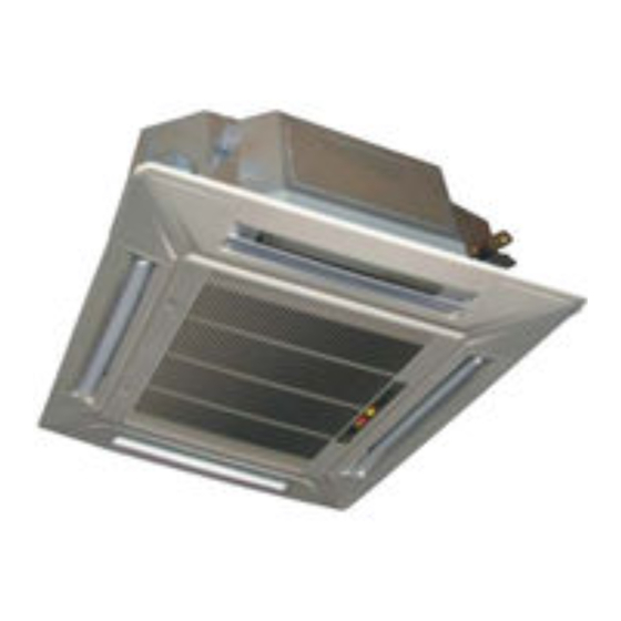
Page 8: Part Names Of Indoor/Outdoor Units
2.2 Part names of Indoor/Outdoor units Cassette Units... - Page 9 A5 Duct Units A6 Duct Units...
- Page 10 Console Units...
- Page 11 Ceiling-floor Units...
- Page 12 HESP DUCT Units...
-
Page 13: Features
2.3 Features 2.3.1 A5 Duct Units 2.3.1.1 Easy Installation: Two air Inlet Styles (Bottom side or Rear side) Air inlet from rear is standard for all capacity; air inlet from bottom is optional. The size of air inlet frame from rear and bottom is same, it’s very easy to move the cover from bottom to rear side, or from rear to the bottom, in order to matching the installation condition. - Page 14 Motor Blower Housing Ventilated Panel 2.3.1.4 Reserved Remote On-off and Central Control Ports Reserved remote on-off ports and central control ports, can connect the cable of an on-off controller or a central controller to realize remote on-off control function or group control function. Remote on-off ports Central control ports 2.3.1.5 Built-in Drain Pump (Optional):...
- Page 15 2.3.1.6 Built-in Display Board The standard indoor unit can be controlled by wired controller. There is a display board with a receiver in the E-box. Move out the display, and fix it in other place, even in the distance of 2m. The unit will realized remoter control. ...
- Page 16 2.3.2 Cassette Units 2.3.2.1 Lower Noise Optimize air channel system design to ensure the maximum quietness and comfort. Noise max down 6dB. 2.3.2.2 Turbo Mode (Optional) Turbo function can boost cooling or heating speed in a short period, and makes the room cool down or heat up rapidly.
- Page 17 2.3.2.6 Build-in Drain Pump The drain pump can lift the condensing water up to 750mm upmost. It’s convenient to install drainage piping under most space condition. 2.3.2.7Terminals For Alarm Lamp and Long-distance On-off Controller Connection Are Standard Reserve terminals for the connection of alarm lamp and long-distance on-off controller, more human control.
- Page 18 2.3.3 Console Units 2.3.3.1. Modern and Elegant Appearance The simple and stylish designs can nicely harmonies with your living space. 2.3.3.2. Two Air-outlet Ways Cooling mode Quick Cooling To maintain room temp Air outlet from top and bottom to make quick cooling ------When the A/C is just switched on, or room temp.
- Page 19 2.3.3.3. Four Air Inlets 2.3.3.4. Low Noise DC indoor fan motor, which has five speeds. Low noise and energy saving. Advanced centrifugal fan technology makes a fast airflow and reduces the indoor noise.
- Page 20 2.3.4 Ceiling-floor Units 2.3.4.1 Two-way Installation The rounded design of the ceiling and floor type air conditioner allows either ceiling or floor-level installation. Ceiling installation saves room space, while floor installation helps prevent the loss of warm air. 2.3.4.2 Brief Design ...
- Page 21 2.3.4.7 Outside Water Pump for Optional When Ceiling Installation.
- Page 22 2.3.5 A6 Duct Units Higher Static Pressure 2.3.5.1. As a ducted air conditioner with medium static pressure, it has the widest static pressure range. The maximum static pressure reaches 160Pa Slim Design 2.3.5.2. The industry Lowest height is designed to be fitted into tight roof spaces. *18K unit - 210mm,24K/36K unit - 249mm,48K unit -300mm 2.3.5.3.
- Page 23 Air intake from rear (Standard) Air intake from bottom (Optional) 2.3.5.5. Communication wire connection A6 duct uses two wires without polarity connection way, which almost has no mistake during the installation. Easy Clean 2.3.5.6. With a larger window design, once the motor and the blower wheels have been detached, heat exchanger and water receiver tray in behind can be seen very clearly.
- Page 24 A ventilation motor (provided by the installer) can be installed inside the fresh air duct to improve the fresh air volume. There are reserved ports for this motor on main PCB (Standard for 3D inverter units, and only optional for DC inverter 53~160 units). 2.3.5.8.Drain pump (Optional) ...
- Page 25 2.3.6 HESP DUCT Units 2.3.6.1 High static pressure design Max static pressure of indoor unit is 200Pa. The longest distance of air supply is 40m, the max height of air supply is 6.5m. Specially recommended for spacious and large rooms like large stores and factories. 2.3.6.2 Easy maintenance ...
-
Page 26: Dimension
3. Dimension 3.1 Indoor Unit A5 Duct Units a ir in le t fr o m r e a r s id e A ir filte r ( o p tio n a l ) 4 - in s ta ll h a n g e r L iq u id s id e 2 5 D r a in p ip e G a s s id e... - Page 27 Cassette Units(9K, 12K, 18K) L iq u id s id e G a s s id e B o d y D r a in h o le W ir in g c o n n e c tio n p o r t ( fo r S e r v ic e ) E - p a r ts b o x 4 - S c r e w h o le...
- Page 28 Cassette Units (24K, 36K, 48K) F r e s h a ir in ta k e 1 3 6 4 - in s ta ll h a n g e r 1 2 6 6 8 0 B o d y G a s s id e L iq u id s id e W ir in g c o n n e c tio n p o r t...
- Page 29 Console Units 2 1 0 7 0 0 H a n g in g a r m 1 9 5 1 6 D r a in p ip e U n it: m m...
- Page 30 Ceiling-floor Units (18K-60K) W ir in g c o n n e c t io n p o r t D r a in d is c h a r g e p o r t 1 2 0 F r e s h a ir in t a k e R e f r ig e r a n t p ip e h o le 1 2 0 H a n g in g a r m...
- Page 31 A6 Duct Units Model unit (KBtu/h) 9/12 inch 27.6 19.9 17.7 21.1 23.6 29.2 14.2 inch 34.6 26.5 23.6 27.8 30.8 36.2 20.0 1100 1001 1140 inch 43.3 30.5 27.6 36.5 39.4 44.9 23.5 1360 1186 1261 1400 inch 53.5 30.5 27.6 46.7...
- Page 32 MHG-60HWFN1-MW 8 5 8 7 7 0 7 0 0 ( s u s p e n s i o n p o s i t i o n ) 4 4 0 2 - Φ 3 . 2 Φ 5 N O T E : 1 6 g r o u p s a l l a r o u n d ( t h e s a m e o f t h e a i r i n l e t f l a n g e )
-
Page 33: Outdoor Unit
3.2 Outdoor Unit Note: The above drawing is only for reference. The appearance of your units may be different. Model unit MOBA30-09HFN1-MT0W inch 30.3 11.8 21.9 33.1 19.2 11.7 MOB30-09HFN1-MX0W MOB30-12HFN1-MV0W MOB30-12HFN1-MT0W MOB01-09HFN1-MW0W inch 31.5 13.1 21.8 34.3 20.2 13.4 MOB01-12HFN1-MV0W MOCA01-18HFN1-MT0W MOCA30-18HFN1-MT0W... - Page 34 Model 1333 1045 MOE30U-48HFN1-M MOE30U-60HFN1-M inch 37.5 16.3 52.5 41.1 25.0 15.9...
-
Page 35: Service Space
4. Service Space 4.1 Indoor Unit A5/A6 Duct Units Ensure enough space required for installation and maintenance. 2 0 0 m m ( 7 .8 7 in ) o r m o r e 3 0 0 m m ( 1 1 .8 1 in ) o r m o r e 6 0 0 m m x 6 0 0 m m /2 3 .6 2 in x 2 3 .6 2 in C h e c k o r ific e All the indoor units reserve the hole to connect the fresh air pipe. - Page 36 Console Units Ceiling-floor Units...
-
Page 37: Outdoor Unit
HESP DUCT 500mm or more 600mm or more Indoor unit Maintenance and repair space 600mmx600mm 4.2 Outdoor Unit ( W a ll o r o b s ta c le ) M o r e th a n 3 0 c m ( 1 1 .8 1 in ) A ir in le t M o r e th a n 6 0 c m M o r e th a n 3 0 c m... -
Page 38: Refrigerant Cycle Diagram
5. Refrigerant Cycle Diagram MOCA30-18HFN1-MT0W, MOCA01-18HFN1-MT0W, MOD30-24HFN1-MT0W, MOD01-23HFN1-MT0W, MOD31-24HFN1-MT0W IN D O O R O U T D O O R E le c t ro n ic C A P I L I A R Y T U B E e x p a n s io n v a lv e L I Q U I D S ID E 2 - W A Y V A L V E... - Page 39 MOD30U-36HFN1-M, MOE30U-48HFN1-M, MOE30U-60HFN1-M IN D O O R O U T D O O R E le c tr o n ic C A P IL IA R Y T U B E e x p a n s io n v a lv e L IQ U ID S ID E 2 - W A Y V A L V E T 3 C o n d e n s e r...
-
Page 40: Wiring Diagram
6. Wiring Diagram 6.1 Indoor Unit CCA3U-09HRFN1-M(C), CCA3U-12HRFN1-M(C), CCA3U-18HRFN1-M(C),MCD-24HRFN1-M(C) CTBU-09HWFN1-M(C), CTBU-12HWFN1-M(C), CTBU-18HWFN1-M(C),CTBU-24HWFN1-M(C) - Page 41 CFAU-09HRFN1-M(C), CFAU-12HRFN1-M(C) MCD-36HRFN1-M(C), MCD-48HRFN1-M(D)
- Page 42 CTBU-36HWFN1-M(C), CTBU-48HWFN1-M(C)
- Page 43 MUEU-18HRFN1-M(C), MUEU-24HRFN1-M(C) MUE-36HRFN1-M(C)
- Page 44 MUE-48HRFN1-M(C) MUE-60HRFN1-MW...
- Page 45 MUE-36HRFN1-M(C),MUE-48HRFN1-M(C)
- Page 46 MUE-60HRFN1-MW MTIU-09HWFN1-M, MTIU-12HWFN1-M, MTIU-18HWFN1-M, MTIU-24HWFN1-M...
- Page 47 MTI-36HWFN1-M , MTI-48HWFN1-M, MHG-60HWFN1-MW Note: If the short connector “J7” or “JR6” is losed, when you don’t use the on-off function, the LED displays error code “CP”.
-
Page 48: Outdoor Unit
6.2 Outdoor Unit MOB30-09HFN1-MX0W, MOB01-09HFN1-MW0W, MOB30-12HFN1-MV0W, MOB01-12HFN1-MV0W, MOCA30-18HFN1-MT0W, MOCA01-18HFN1-MT0W, MOCA31-18HFN1-MT0W, MOD31-24HFN1-MT0W... - Page 49 MOBA30-09HFN1-MT0W, MOB30-12HFN1-MT0W...
- Page 50 MOD30-24HFN1-MT0W, MOD01-23HFN1-MT0W...
- Page 51 MOD30U-36HFN1-M...
- Page 52 MOE30U-48HFN1-M, MOE30U-60HFN1-M PCB board of MOB30-09HFN1-MX0W, MOB30-12HFN1-MV0W, MOCA30-18HFN1-MT0W, MOB01-09HFN1-MW0W, MOB01-12HFN1-MV0W, MOCA01-18HFN1-MT0W, MOCA31-18HFN1-MT0W MOD31-24HFN1-MT0W 2 9 0 -3 3 0 V D C sta n d b y 2 1 0 -3 0 0 V D C ru n n in g c o n n e c t to th e D R m o d u le b rid g e c o n n e c t to re a c ta n c e...
- Page 53 For MOD30-24HFN1-MT0W, MOD01-23HFN1-MT0W, MOD30U-36HFN1-M C o n n e c t t o t h e I n d o o r e v a p . p i p e o u t t e m p . s e n s o r T 2 B - A 、...
- Page 54 For MOBA30-09HFN1-MT0W, MOB30-12HFN1-MT0W L E D 1 0 1 s t a t u s l i g h t ( R e d ) C o n n e c t t o D R m o d u l e F U S E 1 2 0 A / 2 5 0 V A C s l o w f l i c k e r : s t a n d b y (...
- Page 55 IPM board of MOD30-24HFN1-MT0W, MOD01-23HFN1-MT0W, MOD30U-36HFN1-M c o n n e c t t o D C f a n m o t o r T O M A I N 0 V A C ( s t a n d b y ) C N 1 9 C N 5 5 1 0 - 2 0 0 V A C...
-
Page 56: Static Pressure
7. Fan Curves Static Pressure ENC2 Range In. WG (Pa) Model 0.02 0.04 0.08 0.12 0.16 0-0.18 Model≤12 (10) (20) (30) (40) (0-45) 0.04 0.10 0.14 0.18 0.22 0-0.28 Model Model=18 (10) (25) (35) (45) (55) (0-70) (K Btu/h) 0.04 0.10 0.16 0.22... - Page 57 CTBU-09HWFN1-M(C), Code 0 Code 1 Code 2 Code 3 Code 4...
- Page 58 CTBU-12HWFN1-M(C) Code 0 Code 1 Code 2 Code 3 Code 4...
- Page 59 CTBU-18HWFN1-M(C) Code 0 Code 1 Code 2 Code 3 Code 4...
- Page 60 CTBU-24HWFN1-M(C) Code 0 Code 1 Code 2 Code 3 Code 4...
- Page 61 CTB-36HWFN1-M(C) Code 0 Code 1 Code 2 Code 3 Code 4...
- Page 62 CTB-48HWFN1-M(C) Code 0 Code 1 Code 2 Code 3 Code 4...
- Page 63 MTIU-09HWFN1-M, S P 2 A i r v o l u m e m 3 / h ( C F M ) A i r v o l u m e m 3 / h ( C F M ) S P 1 1 2 0 0 ( 7 0 6 ) 1 2 0 0 ( 7 0 6 )
- Page 64 MTIU-12HWFN1-M S P 2 A i r v o l u m e m 3 / h ( C F M ) A i r v o l u m e m 3 / h ( C F M ) S P 1 1 2 0 0 ( 7 0 6 ) 1 2 0 0 ( 7 0 6 )
- Page 65 MTIU-18HWFN1-M A ir v o lu m e m 3/h ( C F M ) A ir v o lu m e m 3/h ( C F M ) S P 2 S P 1 1 8 0 0 ( 1 0 5 9 ) 1 8 0 0 ( 1 0 5 9 ) 1 7 0 0 ( 1 0 0 0 ) 1 7 0 0 ( 1 0 0 0 )
- Page 66 MTIU-24HWFN1-M A ir v o lu m e m 3/h (C F M ) A ir v o lu m e m 3/h (C F M ) S P 2 S P 1 2 6 0 0 ( 1 5 2 9 ) 2 6 0 0 ( 1 5 2 9 ) 2 4 0 0 ( 1 4 1 2 ) 2 4 0 0 ( 1 4 1 2 )
- Page 67 MTI-36HWFN1-M A ir v o lu m e m 3/h ( C F M ) A ir v o lu m e m 3/h ( C F M ) S P 1 S P 2 3 6 0 0 ( 2 1 1 8 ) 3 6 0 0 ( 2 1 1 8 ) 3 4 0 0 ( 2 0 0 0 ) 3 4 0 0 ( 2 0 0 0 )
- Page 68 MTI-48HWFN1-M S P 2 A ir v o lu m e m 3/h ( C F M ) S P 1 A ir v o lu m e m 3/h ( C F M ) 4 2 0 0 ( 2 4 7 1 ) 4 2 0 0 ( 2 4 7 1 ) 4 0 0 0 ( 2 3 5 3 ) 4 0 0 0 ( 2 3 5 3 )
- Page 69 MHG-60HWFN1-MW High Speed Maximum rpm(switch 4) Minimum rpm(switch 0) 1800 2300 2800 3300 3800 Air volume(m3/h) Low Speed Maximum rpm(switch 4) Minimum rpm(switch 0) 1800 2300 2800 3300 3800 Air volume(m3/h)
-
Page 70: Electric Characteristics
8 Electric Characteristics Indoor Unit Model Voltage Min. Max. CCA3U-09HRFN1-M(C) 208-230V 187V 253V CTBU-09HWFN1-M(C) 208-230V 187V 253V MTIU-09HWFN1-M 208-230V 187V 253V CFAU-09HRFN1-M(C) 208-230V 187V 253V CCA3U-12HRFN1-M(C) 208-230V 187V 253V CTBU-12HWFN1-M(C) 208-230V 187V 253V MTIU-12HWFN1-M 208-230V 187V 253V CFAU-12HRFN1-M(C) 208-230V 187V 253V CCA3U-18HRFN1-M(C) 208-230V... -
Page 71: Sound Level
9 Sound Level 9.1 Indoor unit C o n c e a le d D u c t T y p e D is c h a r g e S u c t io n D u c t D u c t 1 .4 m M ic r o p h o n e... - Page 72 1 . 4 m M ic r o p h o n e Noise level dB(A) Model CCA3U-09HRFN1-M(C) CCA3U-12HRFN1-M(C) CCA3U-18HRFN1-M(C) MCD-24HRFN1-M(C) MCD-36HRFN1-M(C) MCD-48HRFN1-M(C)
- Page 73 M ic r o p h o n e 1 .5 m Noise level dB(A) Model CFAU-09HRFN1-M(C) CFAU-12HRFN1-M(C) M ic r o p h o n e 1 . 5 m A ir o u tle t s id e M ic r o p h o n e Noise level dB(A) Model...
-
Page 74: Outdoor Unit
9.2 Outdoor unit Outdoor Unit Microphone 1.0m Note: H= 0.5 × height of outdoor unit Model Noise Level dB(A) MOB30-09HFN1-MX0W MOB01-09HFN1-MW0W MOBA30-09HFN1-MT0W MOB30-12HFN1-MT0W MOB30-12HFN1-MV0W MOB01-12HFN1-MV0W MOCA30-18HFN1-MT0W MOCA01-18HFN1-MT0W MOCA31-18HFN1-MT0W MOD30-24HFN1-MT0W MOD01-23HFN1-MT0W MOD31-24HFN1-MT0W MOD30U-36HFN1-M MOE30U-48HFN1-M MOE30U-60HFN1-M... -
Page 75: Accessories
10 Accessories Duct Units Name Shape Quantity Soundproof / insulation sheath Tubing & Fittings Binding tape Seal sponge Drain joint Drainpipe Fittings (for cooling & heating) Seal ring Wired controller & Its Frame Wired controller Owner's manual Others Installation manual Magnetic ring (twist the electric wires L EMS &... - Page 76 Mounting screw(ST2.9×10-C-H) Remote controller manual Alkaline dry batteries (AM4) Owner's manual Others Installation manual Installation accessory Expansible hook (The product you have might not be provided the Installation hook following accessories Orifice Console Units Name Shape Quantity Installation fittings Hook Remote controller Frame Remote controller &...
-
Page 77: The Specification Of Power
11. The Specification of Power Type 9K-18K Phase 1-phase 1-phase Power Frequency and Voltage 208-230V, 60Hz 208-230V, 60Hz Circuit Breaker/ Fuse (A) 25/20 25/20 Indoor Unit Power Wiring 3-core cable 3-core cable Outdoor Unit Power Wiring (14AWG) (14AWG) 4-core cable 4-core cable (16AWG) (16AWG) - Page 78 12 Field Wiring 9K~24K 36K, 48K...
-
Page 80: Installation Details
blockage of the heat exchanger in the 13 Installation Details outdoor unit. If is built over the unit to prevent direct sunlight, rain exposure, direct strong wend, 13.1Location selection snow and other scraps accumulation, make Indoor unit location selection 13.1.1 sure that heat radiation from the condenser ... - Page 81 48.82 19.69 them using the washers and nuts provided. MTIU-09HWFN1-M/ MTIU-12HWFN1-M 29.2 14.2 MTIU-18HWFN1-M 36.22 1140 MTIU-24HWFN1-M 44.88 23.54 1400 MTI-36HWFN1-M 55.12 23.54 1240 MTI-48HWFN1-M 48.82 27.44 9. Mount the indoor unit onto the hanging 13.2.1.3 Hang indoor unit screw bolts with a block. Position the 1.
- Page 82 ENC1 Toggle switch Capacity(kw) Code Note: The capacity has 5.Please refer to the following static pressure to been set in the install. factory, anyone can’t adjust it 10.5 Model Static Pressure(Pa) except the CTBU-09HWFN1-M(C) 0-45 qualified person CTBU-12HWFN1-M(C) CTBU-18HWFN1-M(C) 0-70 2.
- Page 83 2.Change the mounting positions of ventilation panel and air return flange . 3. When installing the filter mesh, fit it into the flange inclined from air return opening, and 3. When installing the filter mesh, fit it into the then push up. flange as illustrated in the following figure.
- Page 84 Face the concave side of the installation hooks toward the expansible hooks. Determine the length of the installation hooks from the height of ceiling, then cut off the unnecessary part. If the ceiling is extremely high, please determine the length of the installation hook depending on the real situation.
- Page 85 Locate the air conditioner firmly by wrenching the nuts after having adjusted the body's position well. Tighten the screws under the panel hooks till the panel closely stick on the ceiling to avoid condensate water. 13.2.2.5 Install the panel Remove the grille Hang the air-in grill to the panel, then connect the lead terminator of the swing motor and that control...
- Page 86 13.2.3.2 Install the main body Fix the hook with tapping screw onto the wall Capacity (Btu/h) 18K / 24K inch 38.70 8.66 Hang the indoor unit on the hook. 1200 (The bottom of body can touch with floor or inch 47.24 8.66...
- Page 87 13.2.4.4 Install the main body ② Wall-mounted installation ① Ceiling installation (The only installation Hang the indoor unit by insert the tapping method for the unit with drain pump) screws into the hanging arms on the main unit. Remove the side board and the grille. (The bottom of body can touch with floor or suspended, but the body must install vertically.) 13.2.5...
- Page 88 >275 Adjust the position to ensure the gaps between inch 9.65 >10.83 the body and the four sides of ceiling are even. >317 The body's lower part should sink into the inch 11.30 >12.48 ceiling for 10~12 mm. In general, L is half of the screw length of the installation hook.
- Page 89 Note: The panel shall be installed after the wiring connected. Hang the panel to the hooks on the mainbody. If 13.2.6 HESP duct indoor unit installation the panel is with auto-lift grille, please watch the 13.2.6.1 Service space for indoor unit ropes lifing the grille, DO NOT make the ropes enwinded or blocked.
-
Page 90: Outdoor Unit Installation
13.3 Outdoor unit installation 13.3.1 Service space for outdoor unit ( W a ll o r o b s ta c le ) M o r e th a n 3 0 c m ( 1 1 .8 1 in ) A ir in le t M o r e th a n 3 0 c m ( 1 1 .8 1 in ) -
Page 91: Refrigerant Pipe Installation
Do not lean it more than 45, and do not lay it sidelong. Make concrete foundation according to the L e a n C r u d e B u r r specifications of the outdoor units. Fasten the feet of this unit with bolts firmly to prevent it from collapsing in case of earthquake or strong wind. - Page 92 For horizontal refrigerant pipe, the distance between supporters should not be exceed For vertical refrigerant pipe, the distance between supporters should not be exceed 1.5m. 13. Connect the pipe to indoor unit and outdoor unit by using two spanners. ...
- Page 93 2. Air Purging Using Refrigerant Procedure 1). Connect the charge hose to the 3-way Procedure: service port and open the 2-way and 3-way 1). Confirm that both the 2-way and 3-way valve. valves are set to the closed position. Connect the charge hose to the valve at the 2).
- Page 94 Procedure Procedure: 1). Confirm that both the 2-way and 3-way 1). Confirm that both the 2-way and 3-way valves are open. valves are closed. Remove the valve stem caps and confirm that 2). Connect the charge set and a charging the valve stems are open.
-
Page 95: Drainage Pipe Installation
the check valve on the charge set (be careful of the liquid refrigerant). 3) Place the charging cylinder onto the electronic scale and record the weight. 4). Open the valves (Low side) on the charge set and charge the system with liquid refrigerant If the system cannot be charged with the specified amount of refrigerant, or can be charged with a only a small amount at a time... - Page 96 intersection with other pipelines and ensure for confluence PVC50 1440 pipe slope is straight. PVC63 2760 Drainage pipe selection PVC75 5710 The drainage pipe diameter shall not small PVC90 8280 than the drain hose of indoor unit Attention: Adopt PVC40 or bigger pipe to be the ...
- Page 97 The false installation will cause converse B lo w h o le water flow and the slope of the branch pipe In d o o r u n it In d o o r u n it cannot be adjusted. P lu g P lu g Water storage pipe setting...
-
Page 98: Vacuum Drying And Leakage Checking
Continuously infusing water until water level alarmed, check whether the drainage pump could discharge water at once. If water level does not decline under warning water level 3 minutes later, it shall cause shutdown of unit. When this situation happens, the normal startup only can be recovered by turning down power supply and eliminating accumulated water. -
Page 99: Additional Refrigerant Charge
namely ordinary vacuum drying and special Procedures of special vacuum drying are as vacuum drying. follows: Vacuum drying for 1 hour. Ordinary vacuum drying Vacuum damage, filling nitrogen to reach When conduct first vacuum drying, 0.5Kgf/cm2 . connect pressure gauge to the infusing Because nitrogen is dry gas, vacuum mouth of gas pipe and liquid pipe, and... -
Page 100: Engineering Of Insulation
Refrigerant may only be charged after The burning performance should over performed the vacuum drying process. 120℃ Always use gloves and glasses to protect According to the local law to choose your hands and eyes during the charge insulation materials ... -
Page 101: Engineering Of Electrical Wiring
Do not use metal wire tube at the place with The temperature of condensate drainage water acid or alkali corrosion, adopt plastic wire is very low. If insulation is not enough, it shall tube to replace it. form dew and cause leakage to damage the ... - Page 102 Whether the drainage is normal. Whether there is vibration or abnormal noise during operation. Outdoor unit Whether there is vibration or abnormal noise during operation. Whether the generated wind, noise, or condensed of by the air conditioner have influenced your neighborhood.
-
Page 103: Operation Characteristics
14. Operation Characteristics Temperature Cooling operation Heating operation Drying operation Mode 0℃~30℃ 10℃~32℃ Room temperature 17℃~32℃(62℉~90℉) (32℉~86℉) (50℉~90℉) 0℃~50℃ (32℉~122℉) Outdoor temperature -15℃~30℃ (-15℃~50℃(5℉~122℉):For (Entry level) (5℉~86℉) the models with low temperature 0℃~50℃ cooling system) (32℉~122℉) Outdoor temperature -25℃~30℃ -25℃~50℃(-13℉~122℉) (E-Star level) (-13℉~86℉) Outdoor temperature... -
Page 104: Electronic Function
15. Electronic Function 15.1 Abbreviation T1: Indoor room temperature T2: Coil temperature of indoor heat exchanger T3: Coil temperature of condenser 15.2.5 Icon explanation on indoor display board T4: Outdoor ambient temperature (Ceiling Floor) T5: Compressor discharge temperature Td: Target temperature 15.2 Display function 15.2.1 Icon explanation on indoor display board (Duct) - Page 105 off and restart 30s later, if protection happened The Inverter module has a protection function 3 times when fan motor restarts continuously, about current, voltage and temperature. If these the unit will stop and the LED will display the protections happen, the corresponding code failure.
-
Page 106: Operation Modes And Functions
---4°C(39.2°F)≤T2≤7°C(44.6°F), Setting fan T1-Td ℃(° F) Actual fan speed speed compressor will keep the current frequency. H+(H+=H+G) 4.5(8.1) ---T2>7° C(44.6° F), the compressor frequency H(=H) 3.0(5.4) will not be limited. 1.5(2.7) H-(H-=H-G) M+(M+=M+Z) 4.5(8.1) M(M=M) 3.0(5.4) 15.4 Operation Modes and Functions M-(M-=M-Z) 1.5(2.7) L+(L+=L+D) - Page 107 T 1 - T d + 1 .5 ° C ( 3 4 .7 ° F ) 0 .0 ° C ( 0 ° F ) O ff ( H + - L ) * 0 .2 + L - 1 ° C ( - 1 .8 ° F ) T E s to p ( H + - L ) * 0 .4 + L - 2 °...
- Page 108 15.4.6.1 Timing range is 24 hours. failure, the module memorizes the setting 15.4.6.2 Timer on. The machine will turn on conditions before the power failure. The unit will automatically when reaching the setting time. resume the previous operation setting (not 15.4.6.3 Timer off.
- Page 109 15.4.11 Drain pump control Adopt the water-level switch to control the action of drain pump. Main action under different condition :( every 5 seconds the system will check the water level one time) 1. When the A/C operates with cooling (including auto cooling), dehumidifying, and forced cooling mode, the pump will start running immediately and continuously, till stop...
- Page 110 15.4.12 Point check function Press the LED DISPLAY or LED or MUTE button of the remote controller three times, and then press the AIR DIRECTION or SWING button three times in ten seconds, the buzzer will keep ring for two seconds.
- Page 111 Enquiry Display value Meaning Remark information T1,T2,T3,T4, -1F,-1E,-1d,-1c,- -25,-24,-23,-22,-21,-2 1. All the displaying temperature is actual T2B,TP,TH, 1b,-1A value. Targeted -19—99 -19—99 2. All the temperature is ° C no matter what A0,A1,…A9 100,101,…109 Frequency, kind of remote controller is used. b0,b1,…b9 110,111,…119 Actual...
-
Page 112: Troubleshooting
16. Troubleshooting Safety Electricity is stored in capacitors, even when the power supply is shut off. Do not forget to discharge the electricity in the capacitors. Electrolytic Capacitors (HIGH VOLTAGE! CAUTION!) For other models, For other models, connect a discharge resistor (approx.100Ω 40W) or a soldering iron plug between the + and - terminals of the electrolytic capacitor on the opposite side of the outdoor printed circuit board (PCB). -
Page 113: Indoor Unit Error Display
16.1 Indoor Unit Error Display Operation Timer lamp Display LED STATUS lamp ☆ 1 time Indoor unit EEPROM parameter error Communication malfunction between indoor and ☆ 2 times outdoor units ☆ 4 times Indoor fan speed malfunction ☆ 5 times Indoor room temperature sensor (T1 ) malfunction ☆... -
Page 114: Error Display On Two Way Communication Wired Controller
16.2 Error Display on Two Way Communication Wired Controller Display LED STATUS Communication error between wired controller and indoor unit The cassette faceplate is abnormal Indoor unit EEPROM parameter error Communication malfunction between indoor and outdoor units Indoor fan speed malfunction Indoor room temperature sensor (T1 ) malfunction Evaporator coil temperature sensor (T2) malfunction Refrigerant leakage detection... -
Page 115: Outdoor Unit Error Display
16.3 Outdoor unit error display For 9K-24K outdoor unit: LED2 LED1 Problems IU display (Green) (Red) standby for normal Operation normally ☆ Compressor drive board EEPROM error ☆ IPM malfunction or IGBT over-strong current protection Over voltage or too low voltage protection ☆... - Page 116 For 36K-60K Outdoor Unit Problems Error Code Communication malfunction between indoor and outdoor units Current overload protection Outdoor ambient temperature sensor (T4 ) malfunction Condenser coil temperature sensor (T3) malfunction Compressor discharge temperature sensor (T5) malfunction Outdoor unit EEPROM parameter error Outdoor fan speed malfunction Inverter module (IPM) malfunction Over-voltage or under-voltage protection...
- Page 117 will show “-9”.If the temp. is higher than 70 degree, the digital display tube will show “70”. If the indoor unit is not Outdoor ambient temp.(T4) connected, the digital display tube will show: “――” The display value is between 13~129 degree. If the temp. is lower than 13 degree, the digital display tube will show “13”.If the temp.
- Page 118 connected, the digital display tube will show: “――” Actual data*HP*10 1# Indoor unit capacity demand code If capacity demand code is higher than 99, the digital display tube will show single digit and tens digit. (For example, the digital display tube show “5.0”,it means the capacity demand 2# Indoor unit capacity demand code is 15.
-
Page 119: Diagnosis And Solution
16.4 Diagnosis and Solution 16.4.1 EEPROM parameter error diagnosis and solution (E0/F4) E0/F4 Error Code Malfunction conditions Indoor or outdoor PCB main chip does not receive feedback from EEPROM chip. Potential causes Installation mistake ● Faulty PCB ● Trouble shooting: Power off, then restart the unit 2 minutes later. - Page 120 16.4.2 Communication malfunction between indoor and outdoor units diagnosis and solution (E1) For 9K-24K: Error Code Malfunction conditions If the indoor unit does not receive feedback from outdoor unit for 110 seconds 4 consecutive times. Potential causes Wiring mistake ● Faulty indoor or outdoor PCB ●...
- Page 121 Remark: Use a multimeter to test the DC voltage between 2 port and 3 port of outdoor unit. The red pin of multimeter connects with 2 port while the black pin is for 3 port. When AC is normal running, the voltage will move alternately between -50V to 50V.
- Page 122 For 36K-48K: Malfunction Indoor unit does not receive feedback from outdoor unit for 60 conditions seconds OR outdoor unit does not receive feedback from indoor unit for 120 seconds. ● Wiring mistakes Possible causes ● Faulty indoor or outdoor PCB E1 displayed E1 displayed Communication malfunction between indoor...
- Page 123 16.4.3 Fan speed malfunction diagnosis and solution (E3) Error Code Malfunction conditions When indoor fan speed is too low (300RPM) for a certain period of time, the unit ceases operation and the LED displays a failure code. Potential Causes Wiring mistake ●...
- Page 124 Index 1: 1. Indoor DC fan motor (Control Chip is in Fan Motor) Turn power on and while the unit is on standby, measure the voltage between pin1 and pin3 as well as between pin4 and pin3 in fan motor connector. If the value of the voltage is not within the range shown in the following table, the PCB may be experiencing problems and need to be replaced.
- Page 125 16.4.4 Open or short circuit of temperature sensor diagnosis and solution (E4/E5/F1/F2/F3) Error Code E4/E5/F1/F2/F3 Malfunction conditions If the sampling voltage is lower than 0.06V or higher than 4.94V, the LED displays a failure. Potential causes Wiring mistake ● Faulty sensor ●...
- Page 126 16.4.5 Refrigerant Leakage Detection diagnosis and solution (EC) Error Code Malfunction conditions Define the evaporator coil temperature T2 of the compressor starts running as Tcool. If the following occurs 3 times, the display shows "EC" and the unit switches off: In the first 8 minutes after the compressor starts up, if T2 <...
- Page 127 Water-level alarm malfunction 16.4.6 diagnosis and solution Error Code Malfunction conditions If the sampling voltage is not 5V, the LED will display the failure code. ● Wiring mistakes Possible causes ● Faulty water-level switch ● Faulty water pump ● Faulty indoor PCB Power off, then restart the unit 3 minutes Power off, then restart the unit 3 minutes later.
- Page 128 16.4.7 IPM malfunction or IGBT over-strong current protection diagnosis and solution (P0) Error Code Malfunction When the voltage signal the IPM sends to the compressor drive conditions chip is abnormal, the display LED shows “P0” and the AC turn off. Possible causes Wiring mistake ●...
- Page 131 16.4.8 Over-voltage or under-voltage protection diagnosis and solution (P1) Error Code Malfunction conditions Abnormal increases or decreases in voltage are detected by checking the specified voltage detection circuit. Potential causes Power supply issues ● System leakage or blockage ● Faulty PCB ●...
- Page 132 16.4.9 High temperature protection of compressor top diagnosis and solution (P2) Error Code Malfunction decision If the sampling voltage is not 5V, the LED will display the failure. conditions Power supply problems. ● Supposed causes System leakage or block ● PCB faulty ●...
- Page 133 High temperature protection of IPM board diagnosis and solution (P2) High temperature protection of IPM High temperature protection of IPM board board Check whether the radiator Check whether the radiator Fix the radiator well Fix the radiator well is fixed well ? is fixed well ? Check whether electronic Check whether electronic...
- Page 134 16.4.10 Inverter compressor drive error diagnosis and solution(P4) Error Code Malfunction conditions Abnormalities in the inverter compressor drive is detected by a special detection circuit, which can perform communication signal detection, voltage detection, and compressor rotation speed signal detection. Potential causes Wiring mistake ●...
- Page 135 16.4.11 Outdoor IPM module temperature sensor malfunction diagnosis and solution (P7) Error Code Malfunction conditions If the sampling voltage is lower than 0.06V or higher than 4.94V, the LED displays a failure. Potential causes Wiring mistake ● Faulty sensor ● Faulty PCB ●...
- Page 136 16.4.12. J0 Malfunction Malfunction conditions When evaporator coil temperature is more than 60° C, the unit stops. It starts again only when the evaporator coil temperature is less than 54° C Possible causes Faulty evaporator coil temperature sensor Dirty heat exchanger ...
- Page 137 16.4.13. J1 Malfunction Malfunction conditions When the outdoor pipe temperature is more than 65° C, the unit stops. It starts again only when the outdoor pipe temperature is less than 52° C. Possible causes ● Faulty condenser temperature sensor ● Dirty heat exchanger ●...
- Page 138 16.4.14. J2 Malfunction Malfunction conditions When the compressor discharge temperature (T5) is more than 115℃ for 10 seconds, the compressor will stop and not restart until T5 is less than 90℃. ● Refrigerant leakage Possible causes ● Wiring mistake ● Faulty discharge temperature sensor ●...
- Page 139 16.4.15. J3 Malfunction Malfunction decision conditions When the voltage signal that IPM send to compressor drive chip is abnormal, the display LED will show “J3” and AC will turn off. ● Wiring mistake Supposed causes ● Faulty IPM board ● Faulty outdoor fan ass’y ●...
- Page 140 16.4.16. J4 Malfunction J4 displayed J4 displayed Communication error between outdoor main Communication error between outdoor main chip and compressor driven chip chip and compressor driven chip Is there at least one LED in the Is there at least one LED in the compressor driven chip light? compressor driven chip light? Check the signal wire between the...
- Page 141 16.4.17. J5 Malfunction Malfunction conditions If the sampling voltage is not 5V, the LED displays a failure code. ● Possible causes Wiring mistakes ● Faulty overload protector ● System blockages ● Faulty outdoor PCB J5 displayed J5 displayed High pressure protection High pressure protection Are the high pressure Connect high pressure...
- Page 142 16.4.18. J6/P6 Malfunction Malfunction conditions If the sampling voltage is not 5V, the LED displays a failure code. ● Possible causes Wiring mistake ● Faulty over load protector ● System blockages ● Faulty outdoor PCB J6 displayed J6 displayed Low pressure protection Low pressure protection Reconnect the low pressure Reconnect the low pressure...
- Page 143 16.4.19. J8 malfunction Malfunction decision An abnormal voltage rise or drop is detected by checking the specified conditions voltage detection circuit. Supposed causes Abnormal power supply Wiring mistake Faulty bridge rectifier Faulty IPM board...
- Page 144 J8 display J8 display AC power input voltage AC power input voltage protection protection Check whether the power Restart the unit when the power Check whether the power Restart the unit when the power voltage is normal. supply gets normal voltage is normal.
-
Page 145: Main Parts Check
16.5 Main parts check 1. Temperature sensor checking Disconnect the temperature sensor from PCB, measure the resistance value with a tester. Temperature Sensors. Room temp.(T1) sensor, Indoor coil temp.(T2) sensor, Outdoor coil temp.(T3) sensor, Outdoor ambient temp.(T4) sensor, Compressor discharge temp.(T5) sensor. Measure the resistance value of each winding by using the multi-meter. - Page 146 Appendix 1 Temperature Sensor Resistance Value Table for T1,T2,T3,T4 (℃--K) ℃ ℉ ℃ ℉ ℃ ℉ ℃ ℉ K Ohm K Ohm K Ohm K Ohm 115.266 12.6431 2.35774 0.62973 108.146 12.0561 2.27249 0.61148 101.517 11.5 2.19073 0.59386 96.3423 10.9731 2.11241 0.57683 89.5865...
- Page 148 Appendix 2 Temperature Sensor Resistance Value Table for T5,TH (℃--K) ℃ ℉ ℃ ℉ ℃ ℉ ℃ ℉ K Ohm K Ohm K Ohm K Ohm 542.7 68.66 13.59 3.702 511.9 65.62 13.11 3.595 62.73 12.65 3.492 455.9 59.98 12.21 3.392 430.5 57.37...
- Page 149 Appendix 3: ℃ 10 11 12 13 14 15 16 17 18 19 20 21 22 ℉ 48 50 52 54 56 58 60 62 64 66 68 70 72 ℃ 23 24 25 26 27 28 29 30 31 32 33 34 35 ℉...
- Page 150 2. Compressor checking Measure the resistance value of each winding by using the tester. Position Resistance Value ASN98D22UFZ ASM135D23UFZ ATF235D22UMT ATF250D22UMT ATF310D43UMT ATQ420D1UMU ATM115D43UFZ2 Blue - Blue - 1.57Ω 1.75 Ω 0.75 Ω 0.75 Ω 0.65 Ω 0.38Ω 1.87Ω Black Red - Blue...
- Page 151 3. IPM continuity check Turn off the power, let the large capacity electrolytic capacitors discharge completely, and dismount the IPM. Use a digital tester to measure the resistance between P and UVWN; UVW and N. Digital tester Normal resistance value Digital tester Normal resistance value (+)Red...
- Page 152 Heating Chart: HEATING MODE Outdoor temp. ℉ Indoor (℃) Temp. 57 (13.89) 47 (8.33) 37 (2.78) (-2.78) (-8.33) 30.3 28.5 25.3 22.8 20.8 32.5 30.0 26.6 25.4 23.3 33.8 31.5 27.8 26.3 24.9 3.03 2.85 2.53 2.28 2.08 3.25 3.00 2.66 2.54 2.33...
-
Page 153: Disassembly Instructions
17. Disassembly Instructions Note: This part is for reference, the photos may have slight difference with your machine. 17.1 Indoor unit A5 Duct Unit Parts name Procedures Remarks Remove the 1) Screw off the screws to electronic remove the cover of control box electronic control box Four screws... - Page 154 3)Move the display board according to the arrow direction to disassemble Remove the 1) Remove the cover of Repeat the operation of step1 of No1 electronic control box Pull out all the plugs or connectors connected to the PCB and remove the ground wire after remove the screw.
- Page 155 Remover 1) Screw off the fixing the fan screws to remove the motor rear cover board Rear cover board 5 screws 2) Screw off the fixing screws to remove the Rear beam rear beam Total four screws at the left side and right side 3) Remove room Cut off the fastening temperature sensor...
- Page 156 Remove the 1) Remove the rear cover Repeat the operation of step1 of No.5 water board collector 2) Screw off the screws to 4 screws assembly remove the water collector assembly 3 screws 3 screws 3 screws Water collector assembly Remove the 1) Remove the water Repeat the operation of No.6...
- Page 157 4) Remove the evaporator support board 4 screws 5) Screw off the fixing screws to remove the evaporator 1 screw...
- Page 158 Cassette Unit Parts name Procedures Remarks Remove the 3) Open the grille filter Grill switch 4) Remove the filter Note: the filter is easy to be damaged, be careful when removing it. Remove the 4) Open the grille Repeat the operation of step1 of No.1 panel 5) Remove the grille ...
- Page 159 board cover(4 screws) Remove the display board(4 screws) 4 screws Remove the 1) Remove the panel Repeat the operation of step1,2,3 of No.2 swing 2) Screw off 3 screws to motor remove the swing motor assy. 3 screws 3) Screw off 1 screws to remove the swing motor.
- Page 160 3) Pull out all the Indoor fan Pump Water lever Temp. sensors connection wires to other parts, then the PCB can be replaced. Swing motor Power Input Display board 4) There are 2 buckles fixing the PCB. To draw out the PCB, you should open them.
- Page 161 3) Remove the fixing nut to disassemble the fan wheel 4) Pull out the fan wheel Remove the 1) Repeat the operation of fan motor No.6 2) Remove the fixing board of fan motor wire 3 nuts 3) Remove the 5 screws to disassemble the fan motor 5 screws...
- Page 162 assembly 8) Screw off the 4 screws inside 4 holes (1 is under a protection cover) to remove the water collecting assembly. 9) Take out the water collecting assembly Remove the 1) Remove the panel Repeat the operation of No.2 draining 2) Remove the electronic Repeat the operation of No.6...
- Page 163 6) There are 2 screws under the supporter to fixing the pump. Release them to take the pump out of the supporter. Remove the 1) Remove the water Repeat the operation of No.9 evaporator collecting assembly 2) Remove the seal board of evaporator 3 screws 3) Remove the evaporator...
- Page 164 Console Unit No. Parts Procedures Remarks name push push Remove 4) Slide the two the Filter stoppers on the left and right sides to open the front panel 5) Remove the filter. Open the front panel Remove 4) Remove the air Repeat the operation of step1 of No.1 front panel ...
- Page 165 7) Remove the installation plate of electric parts 8) Remove the fixing board of electronic control box 9) Disconnect the DC motor wire, 2 louver motor Louver motor connector wires, evaporator coil Screws of the grounding wire temperature sensor(T2) wire, Louver motor connector and two DC motor connector...
- Page 166 7) Disconnect all the wires of plugs connected to the PCB 8) Remove two fixing screws to remove the PCB 2 screws Remove 1) Remove the Repeat the operation of step1~step of No2. the display electronic board control box 2) Remove the fixing glue to remove the display board...
- Page 167 2) Remove the 1 fixing screw to remove air outlet grille 1 screw assembly 3) Disconnect louver motor wire Repeat the operation of No.7 to remove the air outlet grille Remove 1) Remove the air assembly the louver outlet grille motor of assembly air outlet...
- Page 168 4) Disconnect louver motor wire Louver motor connector 5) Remove 4 fixing screws to disassemble the water collector 4 screws Repeat the operation of No.2 to remove the electronic control Remove 1) Remove the electronic evaporator control box Repeat the operation of No.7 to remove the air outlet grille assembly 2) Remove the air assembly...
- Page 169 4) Remove the evaporator assembly Repeat the operation of No.2 to remove the electronic control Remove 1) Remove the electronic centrifugal control box Repeat the operation of No.7 to remove the air outlet grille 2) Remove the air assembly outlet grille assembly 3) Remove four fixing screws to...
- Page 170 A6 Duct Unit Parts name Procedures Remarks Remove the 6) Screw off the screws to electronic remove the cover of control box electronic control box Five screws 7) Disconnect the fan motor Plug of room temperate sensor wire, room temperature and evaporator sensor wire and temperature sensor...
- Page 171 10) Remove the PCB from the electronic control Press the two fixing holders to remove the Remove the 6) Remove the cover of Repeat the operation of step1 of No1 reactance electronic control box 7) Disconnect the reactance wire Reactance wire 8) Screw off the screw to remover it...
- Page 172 Remover 9) Screw off the fixing the fan screws to remove the motor rear cover board 10 screws Rear cover board 10) Remove the volute shell Press Press the clips to take off the volute shell 11) Remove the fan motor Refer the operation of step2 of No.1 wire from the electronic control box...
- Page 173 Water collector assembly Remove the 10) Remove the water Repeat the operation of No.6 evaporator collector 11) Remove the evaporator sensor Evaporator sensor 12) Remove the pipe clamp board 2 screws 13) Remove the evaporator support board 4 screws 14) Screw off the fixing screws to remove the evaporator 1 screw...
-
Page 174: Outdoor Unit
17.2 Outdoor unit MOB01-09HFN1-MW0W, MOB01-12HFN1-MV0W Part name Procedures Remarks Panel plate How to remove the panel plate. 1)Stop operation of the air conditioner and turn “OFF” the power breaker. 2) Remove the big handle Screws of top panel(3 screws,1 screws is under the big handle) first,then remove the top cover (3 screws) 3 screw of... - Page 175 Fan ass’y Electronic control box 1)After remove the panel plate following procedure 1 reactor Compressor and liquid-gas separator 2) Remove the nut fixing the fan,and remove the ○ fan. ○ 3) Unfix the hooks and then open the electronic control box cover.
- Page 176 4) Disconnect the connector for fan motor from the electronic control board. ○ 5) Remove the four fixing screws of the fan motor, ○ then remove the motor.
- Page 177 Electrical How to remove the parts electrical parts. After finish work of ○ item 1 and item 2, remove the two connectors for the compressor and the reactors. ○ Pull out the two blue wires connected with the four way valve. ○...
- Page 178 heater connector. ○ 5) Disconnect the ○ electronic expansion valve wire from the control board ○ ○ 6) Remove the ground wires . 7) Remove the power supply wires(old label, L1,L2,S, new label 1,2,3). 8) Then remove the electronic control box.
- Page 179 Four-way How to remove the valve The picture of four-way valve may be different from four-way valve. the one on your side. Perform work of item 错误! ○ 1,2,3. Recover refrigerant from the refrigerant circuit. Remove the screw of the coil and then remove the coil.
- Page 180 MOCA01-18HFN1-MT0W Part name Procedures Remarks Panel plate How to remove the panel plate. 4 screws of top panel 1) Stop operation of 3 screws of the air conditioner and turn big handle “OFF” the power breaker. 9 screws of front panel 2) Remove the top panel(7 ○...
- Page 181 ○ 1) After remove the panel plate following procedure 1, remove the hex nut fixing the fan and then remove the fan. ○ 2) Unfix the hooks and then open the electronic control box cover. Compressor wire T3,T4,T5 sensor wire Motor wire Electronic expansion valve Electric pipe heater and Crankcase electric heater...
- Page 182 connector for fan motor from the electronic control board. ○ 4) Remove the four fixing screws of the fan motor. 5) Then remove the fan motor. Electrical How to remove the ○ parts electrical parts. 1) After finish work of item 1 and item 2, remove the connectors for the compressor and reactor.
- Page 183 four way valve. ○ ○ 3) Pull out connectors of the compressor top temp. sensor, condenser coil temp. sensor(T3),outdoor ambient temp. sensor(T4) and discharge temp. sensor(T5). ○ 4) disconnect the electronic expansion valve wire 5) remove the compressor ○ Crankcase electric heater...
- Page 184 6) Remove the grounding screw. 7) Remove the power 错误! supply wires(old label, L1,L2,S; new label 1,2,3). 8) Then remove the electronic control box. ○...
- Page 185 Four-way How to remove the valve The picture of four-way valve may be different from four-way valve. the one on your side. 1) Perform work of ○ item1,2,3. 2) Recover refrigerant from the refrigerant circuit. 3) Remove the screw of the coil and then remove the coil.
- Page 186 MOD01-23HFN1-MT0W Part name Procedures Remarks Panel plate How to remove the panel 3 screws of top panel plate. 1) Stop operation of the air conditioner and turn “OFF” the power breaker. 4 screws of big handle 11 screws of front panel ○...
- Page 187 ○ 1) After remove the panel plate following procedure 1, remove the hex nut fixing the fan and then remove the fan. ○ 2) Unfix the hooks and screws,then open the electronic control box cover. Compressor wire T3,T4,T5 sensor wire 4 way valve Electric pipe heater Electronic expansion...
- Page 188 ○ Remove the four fixing screws of the fan motor. ○ 3) Then remove the fan motor. ○ Electrical How to remove the parts electrical parts. 1) After finish work of item 1 and item 2, remove ○ the three connectors for the compressor and the compressor crankcase heater and the electric...
- Page 189 ○ and discharge temp. sensor(T5). 4)Disconnect the electronic expansion valve wire from the control board ○ ○ ○ 5) Remove the grounding screw. 6) Remove the power supply wires(old label, L1,L2,S; old label 1,2,3). ○ ○ 7) Then remove the electronic control box.
- Page 190 Four-way How to remove the valve The picture of four-way valve may be different from four-way valve. the one on your side. ○ ○ 1) Perform work of item1,2,3. 2) Recover refrigerant from the refrigerant circuit. 3) Remove the screw of the coil and then remove the coil.
- Page 191 MOBA30-09HFN1-MT0W Part name Procedures Remarks Panel plate How to remove the panel Screws of top panel (3 screws,1 screws is under the big handle) plate. 3 screw of Stop operation of the big handle air conditioner and turn “OFF” the power breaker. Remove the big handle first,then remove the top cover (3 screws)
- Page 192 panel plate following ○ procedure 1. 2) Remove the nut fixing the fan, and remove the fan. 3) After remove the top cover .Unfix the hooks and ○ then open the electronic control box cover. T3,T4,T5 sensor Electronic expansion valve 4) Disconnect the connector for fan motor Motor...
- Page 193 5) Remove the four fixing screws of the fan motor, then remove the motor. ④ ○...
- Page 194 Electrical How to remove the parts electrical parts. After finish work of item 1 and item 2, remove the connector for the compressor . ○ Pull out the two blue wires connected with the four way valve. ○ ○ 3) Pull out connectors of the condenser coil temp.
- Page 195 electronic expansion valve wire from the control board ④ 5) Remove the ground wires . ○ ○ 6) Remove the wires(1,2,3). 7) Then remove the electronic control box.
- Page 196 Four-way How to remove the valve The picture of four-way valve may be different from four-way valve. ④ the one on your side. 1)Perform work of item ○ 1,3. 2)Recover refrigerant from the refrigerant circuit. 3)Remove the screw of the coil and then remove the coil.
- Page 197 MOB30-09HFN1-MX0W, MOB30-12HFN1-MV0W, MOB30-12HFN1-MT0W Part name Procedures Remarks Panel plate How to remove the panel plate. Screws of top panel (3 screws, 1 screw is under the big handler) 1) Stop operation of the air conditioner and 3 screws turn “OFF” the power of the big breaker.
- Page 198 ○ ass’y. 1) After remove the panel plate following procedure 1, remove the hex nut fixing the fan and then remove the fan. ○ 2) Unfix the hooks and then open the electronic compressor T3,T4,T5 sensor control box cover. 4 way valve Motor Electronic expansion valve...
- Page 199 3) Disconnect the connector for fan motor ○ from the electronic control board. ○ 4) Remove the four fixing screws of the fan motor. Then remove the fan motor. Electrical How to remove the ○ parts electrical parts. 1) After finish work of item 1 and item 2, remove the connectors for the compressor.
- Page 200 ○ 3) Pull out connectors of the condenser coil temp. sensor(T3),outdoor ambient temp. sensor(T4) and discharge temp. sensor(T5). 4) disconnect the ○ electronic expansion valve wire 5) Remove the ○ ○ grounding screw. 6) Remove the Wires (1,2,3). Then remove the electronic control box.
- Page 201 Four-way How to remove the valve The picture of four-way valve may be different from four-way valve. the one on your side. ○ ○ 1) Perform work of item1,3. 2) Recover refrigerant from the refrigerant circuit. 3) Remove the screw of the coil and then remove the coil.
- Page 202 MOCA30-18HFN1-MT0W, MOCA31-18HFN1-MT0W Part name Procedures Remarks Panel plate How to remove the panel plate. 1) Stop operation of 3 screws of top panel the air conditioner and turn “OFF” the power breaker. 3 screws of big handle 9 screws of front panel 2) Remove the top panel(3 screws).
- Page 203 1) After remove the panel plate following procedure 1, remove the hex nut fixing the fan and then remove the fan. ○ 2) After remove the top cover . Unfix the hooks and then open the electronic control box cover. Compressor wire T3,T4,T5 sensor wire Motor wire...
- Page 204 ○ board. 4) Remove the four fixing screws of the fan motor. ○ Then remove the fan motor. Electrical How to remove the ○ parts electrical parts. 1) After finish work of item 1 and item 2, remove the connectors for the compressor and reactor.
- Page 205 ○ 3) Pull out connectors of ○ the condenser coil temp. sensor(T3),outdoor ambient temp. sensor(T4) and discharge temp. sensor(T5). 4) disconnect the electronic expansion valve ○ wire 6) remove the electric heaters. ○...
- Page 206 6) Remove the grounding screw. 7) Remove the Wires (1,2,3 or L1,L2,S).Then remove the electronic control box. ⑥ ○...
- Page 207 Four-way How to remove the valve The picture of four-way valve may be different from four-way valve. the one on your side. 1) Perform work of ④ ○ item1,3. 2) Recover refrigerant from the refrigerant circuit. 3) Remove the screw of the coil and then remove the coil.
- Page 208 MOD30-24HFN1-MT0W, MOD31-24HFN1-MT0W, MOD30U-36HFN1-M Part name Procedures Remarks Panel plate How to remove the panel 4 screws of big handle plate. Screws of top panel(3screws,1screws is under the big handle) 1) Stop operation of the air conditioner and turn “OFF” the power breaker. Screws of big handle (3 screws)
- Page 209 ass’y. Electronic control box 1) After remove the panel plate following procedure 1 2) Remove the nut fixing the fan,and remove the fan. compressor ○ 3) Unfix the hooks and remove the screws, then ○ open the electronic control box cover.
- Page 210 Compressor T3,T4,T5,sensor Pressure switch wire ○ 4) Disconnect the connector for fan motor Motor wire Electronic expansion 4 way valve from the electronic control ○ board. 5) Remove the four fixing screws of the fan motor, then remove the motor. ○...
- Page 211 Electrical How to remove the ○ parts electrical parts. 1) After finish work of item 1 and item 2, remove the connector for the compressor ○ 2) Pull out the two blue wires connected with the four way valve. 3) Pull out connectors of ○...
- Page 212 ○ 5) Disconnect the ○ electronic expansion valve wire from the control board ○ ○ 6) Remove the ground wires . 7) Remove the wires(1,2,3 or L1,L2,S). Then remove the electronic control box.
- Page 213 Four-way How to remove the valve The picture of four-way valve may be different from four-way valve. the one on your side. 1) Perform work of item 1,3. 2) Recover refrigerant from the refrigerant circuit. 3) Remove the screw of the coil and then remove the coil.
- Page 214 MOE30U-48HFN1-M, MOE30U-60HFN1-M Part name Procedures Remarks Fan ass’y How to remove the fan ass’y. 1) Stop operation of the air conditioner and turn “OFF” the power breaker. 2) Remove the screws of air outlet grille(8 screws) 3) Remove the hex nut fixing the fan.
- Page 215 screw) 7) Disconnect the fan motor connectors FAN1(3p,white) and ⑥ FAN2(3p,white) from DC motor driver board. 8) Remove the fan motor after ⑦ unfastening fixing screws. ⑧ Panel plate How to remove the panel plate. 1) Remove big handle.(2 screws) and water Screws of big handle...
- Page 216 Screws of right-rear panel Electrical How to remove the electrical parts parts. 1) Perform work of item 1 step 5~6 and item 2. IPM board DC Fan PCB board Driver board 2) Disconnect the fan motor connector(5p,white) from the IPM board. ②...
- Page 217 CN2(yellow) CN1(red) CN6(black) CN3(yellow) U、V、W(black) CN9(10p,white) 4) Remove the screws fixing the IPM board and remove the IPM board. Disconnect the connectors and wires connected from PCB and other parts. Connectors: CN8: Discharge temperature sensor CN1/CN3 (2p,white) CN12:Heatsink temperature sensor(2p,red) CN9:T3/T4 temperature sensor (2p/2p,white) CN15: Electronic expansion valve...
- Page 218 wire (yellow-green) after removing the big handle. ⑥ Remove the PCB board. Compressor How to remove the compressor. 1) Perform work of item 1 step 5~6 and item 2.. 2) Extract refrigerant gas. 3) Remove the sound insulation material and crankcase heating cable.
- Page 219 The 4-way How to remove the 4-way valve valve 1) Perform work of item 1 step 5~6 and item 2.. Coil 2) Extract refrigerant gas. Welded parts 3) Remove the electrical parts from item 3. 4) Remove fixing screw of the coil, and remove the coil.
Need help?
Do you have a question about the CTBU-09HWFN1-M(C) and is the answer not in the manual?
Questions and answers