
Subscribe to Our Youtube Channel
Related Manuals for Robur Link Series


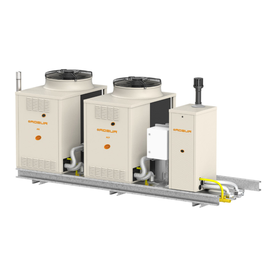
Summary of Contents for Robur Link Series
- Page 1 Installation, use and maintenance manual Link Modular heating unit and heater/chiller powered by gas and renewable energy...
- Page 2 The rights of those who have legitimately filed the registered trademarks contained within this publication are not affected. With the aim of continuously improving the quality of its products, Robur S.p.A. reserves the right to modify the data and contents of this Installation, use and maintenance manual without prior notice.
-
Page 3: Table Of Contents
TABLE OF CONTENTS Introduction Hydraulic system ..........p. 29 ................p. 4 Fuel gas supply ............ p. 34 Recipients ..............p. 4 Combustion products exhaust ...... p. 35 Control device ............p. 4 Flue gas condensate drain ......p. 36 Available languages ..........p. 4 Defrosting water drainage ......p. 36 II Symbols and definitions ......... -
Page 4: Iintroduction
TAC = Technical Assistance Centre authorised by Robur. DANGER CCI Controller (Comfort Controller Interface) = optional Robur control device which lets you manage up to three modulating GAHP units (GAHP A, GAHP GS/WS) of the WARNING same type, for heating only. - Page 5 Warnings „ Moving parts tightness test according to regulations in force. „ Burn hazard Gas smell „ Pressure vessels „ Water-ammonia solution If you smell gas: „ Limescale and corrosion „ Do not use electrical devices such as telephones, „ Chloride concentration multimeters or other equipment that may cause „...
-
Page 6: Iii.2 Compliance
Warnings may exclusively be carried out by a TAC, using only 2014/68/EU "Pressure Equipment Directive" as amend- ▶ original spare parts. ed and added. „ In the event of a failure of the Link, or of one or 811/2013/EU "Energy-Related Products regulation" as ▶... -
Page 7: Features And Technical Data
Features and technical data FEATURES AND TECHNICAL DATA For the characteristics of the individual GAHP/GA/ in variable number: AY modules that make up the Link, and of the con- from 2 to 5 in the case of GAHP/GA only ▶ trol devices, please refer to their respective man- from 2 to 7 in the case of GAHP/GA and AY ▶... -
Page 8: Description Of The Link
Features and technical data DESCRIPTION OF THE LINK supply pressures are available for the same gas in the same country) Each Link is described by a series of letters and digits that 8. (2 letters) = country of destination distinguish its composition and configuration. In order: 9. - Page 9 Features and technical data Figure 1.1 Link description encoding matrix 1AR 1CF 1HR 1AY100S 1AY50S 1AY35S Code Series Description Composition LINK HEAT PUMPS F-GAA HEAT PUMPS F-GAR HEAT PUMPS F-GCF CHILLERS ACF (no HR) F-GCF CHILLER-HEATERS F-EEC CONDENSING BOILERS F-HRE HEAT PUMPS HR-AR-AY F-HAR HEAT PUMPS...
-
Page 10: Hydraulic/Gas Connections
Features and technical data HYDRAULIC/GAS CONNECTIONS Figure 1.2 Position of connections for a Link of condensing boil- Figure 1.3 Position of connections for a Link of condensing boil- er only - 2-pipe - Right-hand side view er only - 4-pipe - Right-hand side view Gas connection [1 1/2"... - Page 11 Features and technical data Figure 1.4 Position of connections for a 2-pipe Link - Right-hand Figure 1.5 Position of connections for a 4-pipe Link with a sin- side view gle AY boiler on the separate circuit - Right-hand side view 1245 1245 Condensate drain connection [1"...
- Page 12 Features and technical data Figure 1.6 Position of connections for a 4-pipe Link with several Figure 1.7 Position of connections for a 4-pipe Link of ACF HR AY boilers on the separate circuit - Right-hand side only view 1113 1245 1113 1245 Gas connection [1 1/2"...
- Page 13 Features and technical data Figure 1.8 Position of connections for a Link of GAHP GS/WS - Right-hand side view 1106 1245 Condensate drain connec- Hot return [2" M] tion [1" F]. Sloping manifold, Cold return [2" M] strictly connect on right side Hot delivery [2"...
- Page 14 Features and technical data Figure 1.10 Position of connections for a 6-pipe Link - Upper view Condensate drain connection [1" F] (only for Link with more than ACF HR recovery hot return (only left connection) [2" M] one condensing module). Sloping manifold, strictly connect on ACF HR recovery hot delivery (only left connection) [2"...
-
Page 15: Dimensions And Weights
Features and technical data DIMENSIONS AND WEIGHTS The dimensions are given for the maximum foot- The weights are given for the maximum weight print configuration. configuration. Figure 1.11 Dimensions and weights of a Link with ACF/A/AR (with 2, 3, 4 and 5 units) - front view 1554 2400 1554... - Page 16 Features and technical data Figure 1.12 Dimensions and weights of a Link with AY (with 2 units) - front view 1554 1554 2400 1828 1554 2400 Configurations 1 GAHP A + 1 AY 35/AY 50 can be replaced by Gitié 2.0 AHAY35/AHAY50 appliances. Configurations 1 GAHP-AR + 1 AY 35/AY 50 can be replaced by Gitié...
- Page 17 Features and technical data Figure 1.13 Dimensions and weights of a Link with 1 ACF/A/AR Figure 1.14 Dimensions and weights of a Link with 1 ACF/A/AR + 1 or 2 AY 35/50 - front and top view + 1 AY 100 + 1 AY 35/50 - front and top view 1554 1554 2400...
- Page 18 Features and technical data Figure 1.16 Dimensions and weights of a Link with 2 ACF/A/AR + 1 or 2 AY 35/50 - front and top view 1554 1554 3610 1307 kg Figure 1.17 Dimensions and weights of a Link with 2 ACF/A/AR + 1 AY 100 - front and top view 1554 1554 3610...
- Page 19 Features and technical data Figure 1.18 Dimensions and weights of a Link with 2 ACF/A/AR + 1 AY 35/50 + 1 AY 100 - front and top view 1554 1554 3610 1352 kg Figure 1.19 Dimensions and weights of a Link with 2 ACF/A/AR + 3 AY 35/50 - front and top view 1554 1554 1554...
- Page 20 Features and technical data Figure 1.20 Dimensions and weights of a Link with 2 ACF/A/AR + 1 AY 100 + 2 AY 35/50 - front and top view 1554 1554 1554 4936 1521 kg Figure 1.21 Dimensions and weights of a Link with 3 ACF/A/AR + 1 or 2 AY 35/50 - front and top view 1554 1554 1554...
- Page 21 Features and technical data Figure 1.22 Dimensions and weights of a Link with 3 ACF/A/AR + 1 AY 100 - front and top view 1554 1554 1554 4936 1706 kg Figure 1.23 Dimensions and weights of a Link with 3 ACF/A/AR + 1 AY 35/50 + 1 AY 100 - front and top view 1554 1554 1554...
- Page 22 Features and technical data Figure 1.24 Dimensions and weights of a Link with 3 ACF/A/AR + 3 or 4 AY 35/50 - front and top view 1554 1554 1554 1554 6490 2093 kg Figure 1.25 Dimensions and weights of a Link with 3 ACF/A/AR + 1 AY 100 + 2 AY 35/50 - front and top view 1554 1554 1554...
- Page 23 Features and technical data Figure 1.26 Dimensions and weights of a Link with 4 ACF/A/AR + 1 AY 35/50 - front and top view 1554 1554 1554 1554 6490 2170 kg Figure 1.27 Dimensions and weights of a Link with 4 ACF/A/AR + 1 AY 100 + 1 AY 35/50 - front and top view 1554 1554 1554...
-
Page 24: Equipment Of A Link With Water Pumps
Features and technical data EQUIPMENT OF A LINK WITH WATER PUMPS The Link equipped with water pumps are also equipped with a check valve, mounted downstream of each water with a check valve, mounted downstream of each water pump, which includes air vent valves, as detailed in the following Figure 1.28 ... -
Page 25: Equipment Of A Link Without Water Pumps
Features and technical data Figure 1.30 Oventrop valve Protection cover Protection cover closing element Pump Oventrop valve Return pipe EQUIPMENT OF A LINK WITHOUT WATER PUMPS Link without independent water pumps that are made up of mixed modules are equipped with an isolation valve on the inlet of each module that cannot always operate si- multaneously with the other modules. -
Page 26: Electrical Specifications
GAHP/GA/AY units. 1.11.2 DDC Controller 1.10 OPERATION MODE The DDC control is able to manage one or more Robur ap- Depending on the type, the GAHP/GA/AY modules in a pliances in ON/OFF mode (GAHP heat pumps, GA chillers) Link can operate in one of the two following modes: or modulating mode (AY boilers). -
Page 27: 1.12 Technical Data
Errors reset. ▶ Possibility to interface with a BMS. Data display and parameters setting. ▶ ▶ DDC functionality may be extended with auxiliary Robur Manifold water temperature probe interface. ▶ devices RB100 and RB200 (e.g. service requests, DHW pro- Diagnostics. ▶... -
Page 28: Minimum Clearance Distances
Transport and positioning „ Aerothermal appliances require a large space, ven- openings. tilated and free from obstacles, to enable smooth flow of air to the finned coils and free air outlet Please refer to the individual GAHP GS/WS and AY above the mouth of the fan, with no air recircula- appliances manuals for further important prescrip- tion. -
Page 29: Heating Engineer
Heating engineer HEATING ENGINEER WARNINGS discussing it in advance with Robur technical service) If there is at least one AY boiler, it is mandatory to General warnings provide Link with water pumps for each individual module. Read the warnings in Chapter III p. 4 , providing important information on regulations and on 3.2.4 Minimum water content... - Page 30 Heating engineer the water and gas piping and any other system expansion tank and with a safety valve. Depending component, removing any residue. on the system water content, assess the need for additional expansion tanks. 3.2.5.3 Minimum components of primary plumbing circuit Always provide, near the appliance: 3.2.6 Schematic hydraulic diagrams...
- Page 31 3.4 p. 32 . This choice needs to be carefully considered in advance with Robur technical service. The Link without water pumps are not available if The common water pump is not supplied with the at least one AY boiler is present.
- Page 32 Heating engineer Figure 3.4 Example of hydraulic system diagram for connection of 2 Link, 2-pipe, without water pumps Anti-vibration connection Primary circuit water pump 11 Check valve Pressure gauge Safety valve 12 DDC panel Flow regulation valve Expansion tank 13 Outdoor temperature probe Sludge filter Buffer tank (and hydraulic separator) Gas connection...
- Page 33 Heating engineer Table 3.2 Glycol effects (GAHP/GA) Water-glycol mixture freezing Percentage of increase in pressure Glycol % Loss of efficiency of unit temperature drops -3 °C -5 °C 6,0% 0,5% -8 °C 8,0% 1,0% -12 °C 10,0% 2,0% -15 °C 12,0% 2,5% -20 °C 14,0%...
-
Page 34: Fuel Gas Supply
Heating engineer „ Do not leave washing residues. valve on the outlet of the Link. 5. Close the isolation valve on the inlet of the Link and 3.2.10 System filling open the second vent valve (Figure 1.29 p. 24 , detail How to fill up the system 6. -
Page 35: Combustion Products Exhaust
Heating engineer Table 3.5 Network gas pressure Gas supply pressure [mbar] Product Country of destination G25.1 G25.3 G2.350 category (1) (2) (3) (1) (2) (2) (3) (2) (3) AL, BG, CY, CZ, DK, EE, FI, GR, HR, IT, LT, MK, NO, RO, SE, SI, SK, TR 2H3B/P AT, CH... -
Page 36: Flue Gas Condensate Drain
UV ray protection must be assured (if from backflowing through the siphon. the valve is in plastic) as well as protection from For GAHP GS/WS indoor modules, Robur uses condensate potential winter freezing of condensate backflow collection siphons with float, which blocks the passage of into the siphon. -
Page 37: Safety Valve Drain
Electrical installer flowing, freezing and damage. plied with the individual units. SAFETY VALVE DRAIN The safety valve drain must be mandatorily ducted outside. Failure to comply with this provision jeop- In the event of indoor installation (only for Link of GAHP ardizes first start-up. -
Page 38: Electrical Power Supply
Electrical installer Figure 4.1 Blind panel: detail of internal terminal blocks on DIN rail K1 K2 R H 1 2 T1 T2 Blind panel of the Link electrical panel (Figure 1.31 p. 26 ) 1-2 24 V coil terminals for water pump request (HR recovery circuit side) AE Power supply input terminals T1-T2 DHW buffer tank thermostat terminals (HR recovery circuit... -
Page 39: Adjustment And Control
The CAN bus communication network, implemented with the cable of the same name, makes it possible to connect and remotely control one or more Robur appliances with the DDC or CCI control devices. It entails a certain number of serial nodes, distinguished intermediate nodes, in variable number ▶... - Page 40 Electrical installer 7. Connect the CCI or the DDC (and possibly the RB100 8. Made the connections, reposition the blind panel and or the RB200) via the CAN bus cable according to the reclose the electrical panel. instructions in the relevant device manuals. Figure 4.4 ...
- Page 41 Electrical installer CAN bus cable section only), or OPEN (detail B) if Figure 4.6 Connection of the CAN bus cable to the CAN-NDG the node is intermediate (two connected CAN bus electronic board cable sections). Figure 4.7 Connection of the CAN bus cable to the control panel JUMPER J11 JUMPER J11 JUMPER J21...
- Page 42 Electrical installer 4.4.5 2 Link + DDC configuration In the last unit of the first Link (which must be connected to the electrical panel of the next Link) the jumper J1 must The DDC panel is connected to the first Link as a terminal be open, as shown in detail B of Figure 4.5 ...
-
Page 43: Water Circulation Pumps
Electrical installer WATER CIRCULATION PUMPS Figure 4.10 Connection of DHW thermostat for heat recovery circuit activation (Link with HR) In Link with water pumps, the individual independent water pumps (1 or 2 for each GAHP/GA/AY module) are already mounted and pre-wired on board the Link. In Link without water pumps, electrical connections must be made (both for power supply and control) of the com- 1 2 T1T2... - Page 44 Electrical installer Figure 4.11 Connection of single- or three-phase water pump directly controlled by the Link (configurations "without water pumps") R S T Blind panel of the Link electrical panel (Figure 1.31 p. 26 ) KQ Appropriate motor protection switch for the water pump used Appropriate fuse for protecting the water pump used Phase of single-phase water pump power supply Water pump disconnector (not supplied)
-
Page 45: First Start-Up
Supply gas pressure complying with the values of Ta- ▶ bustion parameters and may exclusively be carried ble 3.5 p. 35 . out by a Robur TAC. NEITHER the user NOR the in- Correct operation of the flue exhaust duct. ▶ stallation technician is authorised to perform such Power supply mains complying with the appliance's ▶... -
Page 46: Electronic Adjustment On The Appliance - Menus And Parameters
This section is for the end user. Routine switching on/off The use of the device by the end user is only per- mitted after the Robur authorised TAC has com- The appliance may exclusively be switched on/off pleted the first start-up. -
Page 47: Efficiency
Maintenance Once switched on with the control device, under nor- Specific technical and system knowledge is re- mal operating conditions, the Link modules automati- quired for complex settings. Contact a TAC. cally start/stop according to the heating and/or cooling requirements and the logic defined in the control de- EFFICIENCY vice, providing hot/chilled water at the programmed For greater appliance efficiency:... -
Page 48: Pre-Emptive Maintenance
Maintenance breakers of each unit, located in the electrical panel of Link. 3. If required, open any switches/disconnectors located the Link. 2. Open the 4-pole switch in the electrical panel of the upstream of the three-phase supply line of the Link. PRE-EMPTIVE MAINTENANCE For pre-emptive maintenance, comply with the recommendations in Table 7.1 ... -
Page 49: Restarting A Locked-Out Unit
Diagnostics trol manuals. Should you intend to stop the appliance in the winter season, ensure at least one of the following conditions: RESTARTING A LOCKED-OUT UNIT 1. antifreeze function active (Paragraph 3.2.7 p. 32 ) 2. sufficient antifreeze glycol (Paragraph 3.2.8 p. 32 ) 7.5.1 Fault signals on the displays 7.6.1 Prolonged periods of inactivity In case of fault to one (or more) module(s), the relative dis-... - Page 52 Robur mission Robur is dedicated to dynamic progression in research, development and promotion of safe, environmentally-friendly, energy-efficiency products, through the commitment and caring of its employees and partners. Robur S.p.A. advanced technologies for air conditioning via Parigi 4/6 24040 Verdellino/Zingonia (BG) Italy +39 035 888111 - F +39 035 884165 www.robur.com export@robur.it...
Need help?
Do you have a question about the Link Series and is the answer not in the manual?
Questions and answers