Table of Contents
Advertisement
Quick Links
Advertisement
Table of Contents

Related Manuals for Viking Designer DGRT3004BSS


Summary of Contents for Viking Designer DGRT3004BSS
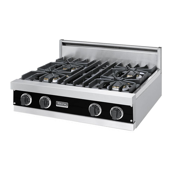
- Page 1 Viking Installation Guide Viking Range Corporation 111 Front Street Greenwood, Mississippi 38930 USA (662) 455-1200 For product information, call 1-888-VIKING1 (845-4641) or visit the Viking web site at vikingrange.com Built-In Gas Rangetops F1239P (080307J)
-
Page 2: Electrical Grounding Instructions
IMPORTANT - PLEASE READ AND FOLLOW •Before beginning, please read these instructions completely and carefully. IF THE INFORMATION IN THIS MANUAL •Do not remove permanently affixed labels, warnings, or IS NOT FOLLOWED EXACTLY, A FIRE OR plates from the product. This may void the warranty. •Please obseve all local and national codes and ordinances. - Page 3 Basic Specifications - VGRT Models Description 36” W. Models 42” W. Models 48” W. Models Overall width 35 7/8” (91.1 cm) 42” (106.7 cm) 47 7/8” (121.6 cm) Overall height To top of spider grate - 9 1/4” (23.5 cm) (Open top Burners only) To top of burner grate - 9 1/8”...
-
Page 4: General Information
GENERAL INFORMATION 1. WARNING: The use of cabinets for storage above the appliance may result in a potential burn hazard. Combustible items may ignite, metallic items may become hot and cause burns. If a cabinet storage is to be provided the risk can be reduced by installing a rangehood that projects horizontally a minimum of 5” (12.7 cm) beyond the bottom of the cabinets. -
Page 5: Wall Installation
10.0” W.C.P. Incoming line pressure upstream from the regulator must be 1” W.C.P. higher than the manifold pressure in order to check the regulator. The regulator used on this range can withstand a maximum input pressure of 1/2 PSI (14.0” W.C.P.) If the line pressure is in excess of that amount, a step- down regulator will be required. - Page 6 Surface Burner Adjustments (For Open Surface Burners) (See Illustration #2) To gain access to the surface burner adjustments: 1. Remove the grates, burner caps, bowls and grate supports. 2. Located the air shutter (A) and loosen the screw (B) that holds the air shutter in place. 3.
- Page 7 When adjustments are required, contact your dealer/installer for corrections. If assistance is not available, contact Viking Range Corporation Preferred Service for the nearest authorized service agent at (662) 451- 4133. All corrections to installation are the responsibility of the dealer/installer or end user.
-
Page 8: Wiring Diagram
WIRING DIAGRAM GAS RANGETOPS For connection to the factory installed terminal block, use copper or aluminum conductors. WARNING ELECTRICAL GROUNDING INSTRUCTIONS is appliance is equipped with a three-prong grounding plug for your protection against shock hazard and should be plugged directly into a properly grounded three-prong receptacle. Do not cut or remove the grounding prong from thid CAUTION Label all wires prior to disconnection when servicing controls.