
Related Manuals for Fullwat PDA5500-STATION


Summary of Contents for Fullwat PDA5500-STATION
- Page 1 PDA5500-STATION pure sine wave Power DC-AC Inverter Multi-function INVERTER/CHARGER: inverter + MPPT solar charger + battery charger...
-
Page 3: Basic System Architecture
1. INTRODUCTION This is a multi-function inverter/charger, combining functions of inverter, MPPT solar charger and battery charger to offer uninterruptible power support with portable size. Its comprehensive LCD display offers user-configurable and easy-accessible button operation such as battery charging current, AC/solar charger priority, and acceptable input voltage based on different applications. -
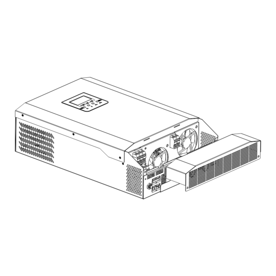
Page 4: Product Overview
4. PRODUCT OVERVIEW Indication LCD Display Function buttons PV Input Status indicator Power ON/OFF switch Battery input Charging indicator AC input Circuit breaker Fault indicator AC output RS485/RS232 communication port - 4 -... -
Page 5: Installation
5. INSTALLATION 5.1 Unpacking and Inspection Befare installation, please inspect the unit. Be sure that nothing inside the package is damaged. You should have received the following items inside of package: • The unit x 1 • User manual x 1 •... -
Page 6: Ac Input/Output Connection
Before connecting to AC input power source, please install a separate AC breaker between inverter and AC input power source. This will ensure the inverter can be securely disconnected during maintenance and fully protected from over current of AC input. The recommended spec of AC breaker is 50A for PDA5500-STATION. Caution!! There are two terminal blocks with “IN”... - Page 7 Suggested cable requirement for AC wires. Model Gauge Torque value PDA5500-STATION 8AWG 1.4~1.6 Nm Please follow below steps to implement AC input/output connection: 1. Before making AC input/output connection, be sure to open DC protector or disconnector first. 2. Remove insulation sleeve 10mm for six conductors. And shorten phase L and neutral conductor N 3mm.
- Page 8 To reduce risk of injury, please use the proper recommended cable size as below. Model Wire size Cable (mm Torque value (max) PDA5500-STATION 1*12AWG 1.2Nm PV Module selection: When selecting proper PV modules, please be sure to consider below parameters: 1.
- Page 9 Please follow below steps to implement PV module connection: 1. Remove insulation sleeve 10mm for positive and negative conductors. 2. Check correct polarity of connection cable from PV modules an PV input connectors. Then, connect positive pole (+) of conncection cable to positive pole (+) of PV input connector.
-
Page 10: Power On/Off
6. OPERATION 6.1 Power ON/OFF Once the unit has been properly installed and the batteries are connected well, simply press ON/OFF switch (located on the button of the case) to turn on the unit. 6.2 Operation and Display panel The operation and display panel, shown in below chart, is on the front panel of the inverter. It includes three indicators, four function keys and a LCD display, indicating the operating status and input/output power information. -
Page 11: Lcd Display Icons
6.3 LCD Display Icons Icon Function description Input source information Indicates the AC input. Indicates the PV input. Indicate input voltage, input frequency, PV voltage, battery voltage and charger current. Configuration program and fault information Indicates the setting programs. Indicates the warning and fault codes. Warning: flashing with warning code. - Page 12 In battery mode, it will present battery capacity. Load percentage Battery voltage LCD Display <1.717V/cell 1.717V/cell ~ 1.8V/cell Load>50% 1.8 ~ 1.883V /cell >1.883 V /cell <1.817V/cell 1.817V/cell ~ 1.9V/cell 50%>Load >20% 1.9 ~ 1.983V/cell >1.983 <1.867V /cell 1.867V/cell ~ 1.95V/cell Load<20% 1.95 ~ 2.033V/cell >2.033...
- Page 13 6.4 LCD Settings After pressing and holding ENTER button far 3 seconds, the unit will enter setting mode. Press “UP” or “DOWN” button to select setting programs. And then, press “ENTER” button to confirm the selection or ESC button to exit. Setting Programs Program Description...
- Page 14 Setting Programs Program Description Selectable option AGM (default) Flooded Battery type User-Defined If “User-Defined” is selected, battery charge voltage and low DC cut-off voltage can be set up in program 26, 27 and 29. Restart disable Restart enable (default) Auto restart when overload occurs Restart disable Restart enable...
- Page 15 Setting Programs Program Description Selectable option Battery fully charged Setting voltage point back to battery mode when selecting “SBU 54V (default) priority”. If this inverter/charger is working in Line, Stand by or Fault mode, charger source can be programmed as below: Solar energy will charge battery as first Solar first priority.
- Page 16 Setting Programs Program Description Selectable option Backlight on (default) Backlight off Backlight control Alarm off Alarm on (default) Beeps while primary source is i nterrupted Bypass disable Overload bypass: Bypass enable (default) When enabled, the unit will transfer to line mode if overload occurs in battery mode.
-
Page 17: Display Settings
6.5 Display Settings The LCD display information will be switched in turns by pressing “UP” or “DOWN” key. The selectable information is switched as below order: input voltage, input frequency, PV voltage, MPPT charging current, MPPT charging power, battery voltage, output voltage, output frequency, load percentage, load in Watt, load in VA, load in Watt, DC discharging current, main CPU Version and second CPU Version. - Page 18 Selectable information LCD display Output frequency=50Hz Output frequency Load percent=70% Load percentage When connected load is lower than 1kVA, load in VA will present xxxVA like below chart. Load in VA When load is larger than 1kVA, load in VA will present x.xkVA like below chart.
- Page 19 6.6 Operating mode descritption Operation mode Description LCD display Charging by utility and PV energy. Standby mode / Power saving Charging by utility. mode Note: * Standby mode: The inverter is not turned on yet but at this No output is supplied time, the inverter can charge by the unit but it still can battery without AC output.
- Page 20 Operation mode Description LCD display Charging by utility and PV energy. Charging by utility If “SUB” is selected as output source priority and solar energy is not sufficient to provide the load, solar energy and the utility will provide the loads The unit will provide and charge the battery at the same time.
-
Page 21: Fault Reference Code
6.7 Fault reference code Fault code Fault Event Icon on Fan is locked when inverter is off. Over temperature. Battery voltage is tooo high. Battery voltage is too low. Output short circuited ar over temperature is detected by internal converter components. Outout voltage is too high. -
Page 22: Warning Indicator
6.8 Warning indicator Warning Warning event Audible alarm Icon flashing code Fan is locked when inverter Beep three times every is ON. second. Battery is over-charged. Beep once every second. Low battery. Beep once every second. Beep once every 0.5 Overload. -
Page 23: Specifications
7. SPECIFICATIONS Table 1 - Line mode specifications Inverter model PDA5500-STATION Input voltage waveform Sinusoidal (utility or generator) Nominal input voltage 230Vac 170Vac±7V (UPS); Low loss voltage 90Vac±7V (Appliances) 180Vac±7V (UPS); Low loss return voltage 100Vac±7V (Appliances) High loss voltage 280Vac±7V... - Page 24 Table 2 - Inverter mode specifications Inverter model PDA5500-STATION Rated output power 5.5KVA/5.5KW Output voltage waveform Pure Sine Wave Output voltage regulation 230Vac±5% Output frequency 60Hz or 50Hz Peak efficiency Overload protection 5s@≥150% load; 10s@110%~150% load Surge capacity 2* rated power for 5 seconds Nominal DC input voltage 48.0Vdc...
- Page 25 Table 3 - Inverter mode specifications Inverter model PDA5500-STATION Charging Current (UPS) @ Nominal Input Voltage Flooded battery 58.4 Bulk charging voltage AGM / Gel battery 56.4 Floating charging voltage 54Vdc Charging algorithm 3-step Battery voltage, per cell Chargin current, % Voltage 2.43Vdc (2.35Vdc)
-
Page 26: Troubleshooting
8. TROUBLE SHOOTING Problem LCD / LED / Buzzer Explanation /Possible What to do cause Unit shuts down LCD/LEDs and buzzer will The battery voltage is too 1. Re-charge battery. automatically during startup be active for 3 seconds low (<1.91V/Cell) 2. -
Page 27: Appendix: Approximate Back-Up Time Table
9. APPENDIX: Approximate Back-up Time Table Model Load (W) Backup Time @ 48Vdc 100Ah (min) Backup Time @ 48Vdc 200Ah (min) 1288 1000 1500 2000 2500 PDA1500-STATION (12V) 3200 3500 4000 4500 5000 Note: Backup time depends on the quality of the battery, age of battery and type of battery. Specifications of batteries may vary depending on different manufacturers. - Page 28 Agente importador A48.139.786 UKAI S.A. Ribera de Elorrieta, 7C 48015 - Bilbao - SPAIN Designed in EU - Made in P RC...
Need help?
Do you have a question about the PDA5500-STATION and is the answer not in the manual?
Questions and answers