Aprilaire 5000 Installation Instructions Manual
Electronic air cleaner
Hide thumbs
Also See for 5000:
- User manual ,
- Owner's manual (20 pages) ,
- Installation insructions (16 pages)

Related Manuals for Aprilaire 5000


Summary of Contents for Aprilaire 5000
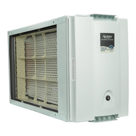
- Page 1 INSTALLATION INSTRUCTIONS Model 5000 Air Cleaner Electronic Air Cleaner Product Info & Digital Manual...
-
Page 2: Table Of Contents
TABLE OF CONTENTS SAFETY INSTRUCTIONS SAFETY INSTRUCTIONS . . . . . . . . . . . . . . . . . . . . . . . . . . . . . . . . . . . . . . . . . . . . . 2 WARNING SPECIFICATIONS . -
Page 3: Specifications
Electrical – Current/Power Consumes less than 50 watts with high voltage active Maximum Equipment Weight Cabinet will support 400 lb . static load TABLE 2: MODEL 5000 INITIAL AIRFLOW RESISTANCE (INCHES w .c . ) Airflow (CFM) 1000 1200 1400... -
Page 4: Components
COMPONENTS FIGURE 2: MODEL 5000 COMPONENTS A. INNER HOUSING ASSEMBLY B. CONTROL ELECTRODE C. IONIZER FRAME D. INNER HOUSING E. OUTER HOUSING WITH DOOR RETAINERS F. LATCHES G. POWER PACK/DOOR ASSEMBLY H. ON/OFF SWITCH I. MODEL 501 AIR FILTER J. PLEAT SPACERS (6) -
Page 5: Locating The Air Cleaner
12” 90-1347 45° MAX. INSTALLATION OPTIONS MINIMIZE ANGLES WHERE The Model 5000 can be installed in a POSSIBLE variety of ways . FIGURES 4-7 show some of the possibilities . LEFT SIDE INSTALL SHOWN 90-1160A 90-1161A The air cleaner may be installed on the left or right side of the air handler . -
Page 6: And Inner Housing Assembly
INSTALLING THE OUTER HOUSING AND INNER HOUSING ASSEMBLY WARNING FIGURE 8 ELECTRIC SHOCK HAZARD: 120 volts may cause serious injury from electric shock. Disconnect electrical power to AIRFLOW LABEL the HVAC system before starting installation or servicing. Leave power disconnected until installation/service is completed. -
Page 7: Wiring And Start Up
FOR 120-VOLT EQUIPMENT WITHOUT EAC TERMINALS: on and off as described, continue with Step 10 . a. Use an Aprilaire Model 51 Current Sensing Relay to wire 10. If the light stays on after the blower has stopped running, a single receptacle outlet as shown in FIGURE 11 . Refer to... - Page 8 FIGURE 10 FIGURE 11 IT IS COMMON TO SEE SPADE LINE TERMINALS ON THE HVAC VOLTAGE EQUIPMENT CONTROL CENTER REFER TO THE INSTRUCTIONS WIRE CIRCUIT BOARD. USE ONLY FULLY PROVIDED WITH THE MODEL 51 INSULATED FITTINGS (FEMALE FOR WIRING DETAILS. QUICK DISCONNECTS SHOWN).
-
Page 9: Troubleshooting Guide
TROUBLESHOOTING GUIDE PROBLEM POSSIBLE CAUSE(S) SOLUTION(S) ON/OFF switch not in ON position Turn switch ON . Air cleaner not plugged in Plug in air cleaner . Light does not come on at all after Insufficient current to activate Wrap blower common wire around relay bracket more . See FIGURE 12 on 90 seconds Model 51 relay page 8 for wire wrapping method . -
Page 10: Maintenance Recommendations
Always use genuine AprilAire Model 501 replacement air filter. with a clean cloth . The Model 5000 is designed to work only with genuine AprilAire Model 501 replacement air filter. Use of other air filters will TO CLEAN THE IONIZER WIRES: damage your Model 5000 Electronic Air Cleaner . - Page 11 FIGURE 14: MAINTENANCE A. BUS BAR B. IONIZER WIRES C. IONIZER FRAME D. CONTROL ELECTRODE E. INNER HOUSING ASSEMBLY F. MEDIA GROUND CONTACTS G. CONTROL ELECTRODE GROUND CONTACT 90-1151...
-
Page 12: Applications With A Humidifier
B2701048C • 10007971 • 10.23 © 2023 AprilAire | aprilairepartners.com | 800.334.6011 AprilAire reserves the right to change specifications without notice.
Need help?
Do you have a question about the 5000 and is the answer not in the manual?
Questions and answers