Table of Contents
Advertisement
Quick Links
Advertisement
Table of Contents

Related Manuals for Datacom DM4170


Summary of Contents for Datacom DM4170
- Page 1 DM4170 CARRIER ETHERNET SWITCH INSTALLATION GUIDE...
-
Page 2: Legal Note
In spite the fact that all the precautions were taken in development of the present document, DATACOM shall not be held responsible for eventual errors or omissions as well as no obligation is assumed due to damages resulting from the use of the information included in this guide. -
Page 3: Contacts
DM4170 – Instalation Guide Contacts CONTACTS ECHNICAL UPPORT Datacom has available a support portal - DmSupport, to help the customers in use and config of our equipment. Access DmSupport made through link: https://supportcenter.datacom.com.br In this site the following are available: firmwares, technical datasheets, config guide, MIBs and manuals for download. -
Page 4: Product Documentation
DM4170 – Instalation Guide Product Documentation PRODUCT DOCUMENTATION BOUT THIS OCUMENT This document is part of a set of documents prepared to provide all necessary information about DATACOM products. OFTWARE LATFORM – UICK ONFIGURATION UIDE Provides instructions on how to set the functionalities in a quick manner in the equipment –... -
Page 5: Table Of Contents
DM4170 – Instalation Guide Product Documentation TABLE OF CONTENTS LEGAL NOTE ....................................1 WARRANTY ....................................2 CONTACTS ....................................3 ..............................3 ECHNICAL UPPORT ..............................3 ENERAL NFORMATION PRODUCT DOCUMENTATION ..............................4 ............................... 4 BOUT THIS OCUMENT ..............................4 OFTWARE LATFORM .............................. - Page 6 DM4170 – Instalation Guide Product Documentation 3.11.1 Pin Settings and Polarity ..................... 19 3.11.2 Power Cables ..........................20 3.12 P ..........................21 ROTECTIVE ROUNDING DM4170 INSTALLATION ............................22 DM4170 P ........................ 22 ACKAGE CONTENTS ........................22 DENTIFYING THE PRODUCT ...................... 22 REPARING THE INSTALLATION SITE .......................
-
Page 7: Introducing The Product's Installation Manual
MANUAL 1.1 A BOUT THIS MANUAL This manual can be used for the DM4170 switches, providing information about the installation of this product line. The document focuses on the electrical and physical part, indicating the states of the equipment as well as the installation of its hardware. It is assumed that the individual or individuals who will manage any aspect of the product have basic knowledge of electrical installations, Ethernet interfaces and general telecommunications knowledge. -
Page 8: Getting Started
DM4170 – Instalation Guide Getting started Icon Category Description point designated for the recycling of electrical and electronic equipment. Separate collection and recycling of equipment at the time of disposal help preserve natural resources ensure that equipment recycled so as to protect people's health and the environment. - Page 9 DM4170 – Instalation Guide Optical modules use invisible radiation laser transmitters. Although most SFP/SFP+/QSFP+ on the market meet LASER safety specifications, never look directly at the terminals of a module or an optical cord. Exposure to laser emission may cause partial or total loss of vision.
-
Page 10: Hardware Description
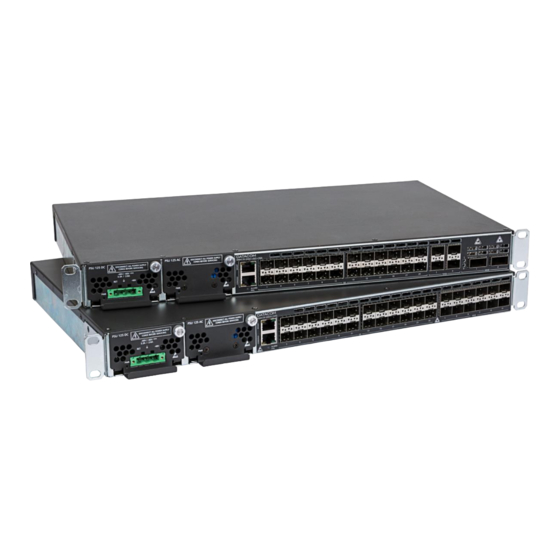
3 HARDWARE DESCRIPTION This chapter describes the DM4170 line’s hardware features. 3.1 P RODUCT VERVIEW The DM4170 product line has two product versions as shown below: Figure 1 - DM4170 24GX+12XS Figure 2 - DM4170 24GX+4XS+2QX 3.2 M DM4170 24GX+12XS... -
Page 11: Model Dm4170 24Gx+4Xs+2Qx
Auxiliary Safety Ground USB Storage Interface Alarm Interface (2 inputs and 1 output) PSU2 Power Input (Backup) PSU1 Power Input (Main) Table 2 – DM4170 24GX+12XS Interface Description 3.3 M DM4170 24GX+4XS+2QX ODEL Figure 4 - DM4170 24GX+4XS+2QX Views 204.0302.05 – February/2021... -
Page 12: Equipment Status Leds
Table 3 – DM4170 24GX+4XS+2QX Interface Description 3.4 E QUIPMENT STATUS The DM4170 switches have two status LEDs on the front panel, the ALARM/FAIL LED on the Mainboard, and the PWR LED on each PSU. The table below describes the LED status behavior of the equipment. -
Page 13: Serial Console Interface (Rs-232)
(RS-232) ERIAL CONSOLE INTERFACE The DM4170 switch has a console port for local management. The console port uses an RJ45 connector. A cable with a male RJ45 connector and a female DB9 connector must be used for the connection to a computer or laptop. -
Page 14: Ethernet Management Interface (Mgmt)
3.8 E (MGMT) THERNET ANAGEMENT NTERFACE The DM4170 has a Gigabit Ethernet interface used for local or remote management of the switch. For details on how to use it, see the chapter, . This CCESSING THE RODUCT interface has two status LEDs whose behavior is described in... -
Page 15: Indicator Leds Of The Gigabit Ethernet Optical Interfaces
SFP+ Ethernet 10 Gigabit Optical Interfaces (10GBase-X) The DM4170 versions have 4 or 12 10 Gigabit Ethernet optical interfaces depending on the model, all using an SFP+ connector. There are LINK/ACT and SPEED indicator LEDs that are built into the connectors corresponding to each interface. The ports are identified in the front panel printing, but only odd ports (bottom ports) are numbered. -
Page 16: Qsfp+ Ethernet 40 Gigabit Optical Interfaces (40Gbase-X)
Table 7 – Indicator LEDs of 10GbE SFP+ interfaces 3.9.4 QSFP+ Ethernet 40 Gigabit Optical Interfaces (40GBase-X) The DM4170 QX versions have 2 optical 40 Gigabit Ethernet interfaces, all using QSFP+ connectors. There are bicolor LEDs indicating the status of each interface. -
Page 17: Alarm Input And Output
NPUT AND UTPUT The DM4170 has two alarm inputs and one alarm output in an RJ45 connector. Alarm 1 and 2 inputs are isolated via optocoupler. External alarm detection occurs when the voltage difference between IN+ and IN- reaches 12V. Table 10 presents the voltages and status for alarm 1 and 2 inputs. - Page 18 DM4170 – Instalation Guide HARDWARE DESCRIPTION The DM4170 switches have two PSU models: the PSU 125 DC that operates with DC -48/60 Vdc power supply and the PSU 125 AC that operates with 100/240Vac (50/60Hz) AC power supply. For further details read the...
-
Page 19: Pin Settings And Polarity
DM4170 – Instalation Guide HARDWARE DESCRIPTION On the PSU 125 DC, fuses F1 and F2 support currents up to 15A. They are 86V Fast Acting. If necessary, only replace it with one of the same specifications. The F3 output fuse supports currents up to 15A. It is also 86V Fast Acting. -
Page 20: Power Cables
DM4170 – Instalation Guide HARDWARE DESCRIPTION 3.11.1.2 PSU 125 DC The figure below shows the pinout of the TERMINAL BLOCK connector for powering the equipment. Figure 14 – DC Power Connector Pin Settings 3.11.2 Power Cables 3.11.2.1 PSU 125 AC The PSU 125 AC includes a 3-meter power cord in the standard female IEC 320/C14 for the NBR 14136 plug. -
Page 21: Protective Grounding
Table 11 – Installing the PSU 125 DC power supply 3.12 P ROTECTIVE ROUNDING The DM4170 switches have a Protective Ground point on the rear panel. This connector must be connected to the installation ground (FGND) as instructed in DM4170 I chapter. -
Page 22: Dm4170 Installation
4.2 I DENTIFYING THE PRODUCT Make sure that the product received matches the figures in this guide. The DM4170 has a label on the rear side of the mechanics. It contains model information, product code and serial number. Check if there is any divergent information on the label regarding the information on the packaging. -
Page 23: Environment Requirements
4.6 C PROTECTIVE GROUNDING ONNECTING THE The DM4170 has a place on its rear panel to attach a cable to connect the Protective Grounding. The grounding cable is not part of the basic accessories shipped with the switch. The cable indicated for the installation must have a thickness of 10 to 12 AWG. The color of the cable must follow the specific requirements of the country where the switch will be installed;... -
Page 24: Ventilation
4.7 V ENTILATION The DM4170 switch ventilation airflow is provided by the inlets on the front and left sides of the equipment and through the outlets on the rear, as in figure below. For the correct operation of the cooling system it is important that the air inlets and outlets are unobstructed and that the free areas of 5cm (2 inches) are respected on the rear panel and on the left side of the switch. -
Page 25: Connecting To Power Supply
’ HECKING THE PRODUCT S OPERATION Considering that the DM4170 was installed according to the guidelines in this manual, the steps below indicate whether the equipment is operating normally. Immediately after the unit is powered by either of the power Step 1 inputs, the power-on PSU PWR indicator will light up. -
Page 26: Installing Sfp/Sfp+/Qsfp+ Modules
5 INSTALLING SFP/SFP+/QSFP+ MODULES This chapter describes how SFP/SFP+/QSFP+ modules must be installed and removed. It also informs about DATACOM guidelines for the cleaning and storage of modules and optical fibers. SFP (Small Form-factor Pluggable), SFP+ and QSFP+ modules are inserted into the switch's SFP, SFP+ and QSFP+ ports, operating as transceivers between the switch and the selected optical communication path. -
Page 27: Isfp/Sfp+ M
DM4170 – Instalation Guide Installing SFP/SFP+/QSFP+ Modules 5.1 I SFP/SFP+ M NSTALLING ODULES Follow the steps below to install SFP/SFP+ modules to the switch. Insert the module into the SFP/SFP+ slot and press it until it is Step 1 firmly inserted, as shown in the figure. -
Page 28: Removing Sfp/Sfp+ Modules
DM4170 – Instalation Guide Installing SFP/SFP+/QSFP+ Modules 5.2 R SFP/SFP+ M EMOVING ODULES Before removing the optical cords, it is recommended that you check if there are labels on them that indicate to which equipment and port they should be connected, facilitating their identification later. -
Page 29: Accessing The Product
(710.0137.xx - supplied with the product) and run a terminal emulator such as Hyper Terminal or similar on a computer or laptop. The DM4170 default setting is baud rate 9600, with 1 stop bit and no parity, as in F IGURE Figure 25 –... -
Page 30: Management Through The Console Interface Management Through The Ethernet Outband Interface (Mgmt)
Command Line Interface (CLI). The CLI is accessible through the console interface or through SSH and Telnet clients. Only one account is accessed in the factory default setting of the DM4170 product line: admin 204.0302.05 – February/2021... -
Page 31: Management Access Configuration
Applying and saving configuration changes: Step 5 (config)# commit Table 3 – DM4170 Login Due to security issues it is strongly recommended that you change the admin account password immediately after the device is installed. See the Command Reference Guide for instructions on how to change passwords. -
Page 32: Technical Specifications
USB Host (type A) USB Device (type B) 100Base-FX/1000Base-X(SFP) 10/100/1000Base-T (RJ45) 1000Base-X/10GBase-X (SFP+) 40GBase-X (QSFP+) Table 204 - DM4170 Interfaces 7.2 Power Supply and Consumption 7.2.1 Power Supply AC/DC (Connector IEC 320/c14) PSU 125 AC PSU 125 DC 100 to 240Vac (± 10%) Rated operating voltage -48 to -60Vdc (±... -
Page 33: Hysical Pecifications
DM4170 – Instalation Guide Maximum PSU 125 DC 3.9A 3.6A current (Amperes) PSU 125 AC 1.6A 1.5A Table 22 – DM4170 Power Consumption 7.3 P HYSICAL PECIFICATIONS DM4170 DM4170 24GX+12XS 24GX+4XS+2QX Height 42.5 mm 42.5 mm Width (with Brackets) 482 mm... -
Page 34: Standards And Regulations
DM4170 – Instalation Guide 8 STANDARDS AND REGULATIONS Class Standard Description Directive 2014/30/EU Electromagnetic Compatibility Requisitos técnicos compatibilidade Ato 1120 eletromagnética para avaliação da conformidade de produtos de telecomunicações. Telecommunication network equipment; Electromagnetic Compatibility (EMC) requirements; ETSI EN 300 386...
Need help?
Do you have a question about the DM4170 and is the answer not in the manual?
Questions and answers