Table of Contents
Advertisement
Quick Links
T
S
RI
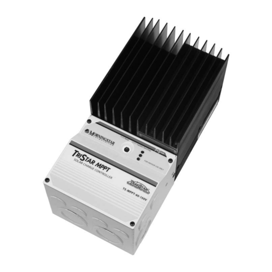
TAR MPPT
Solar System Controller
Installation and Operation Manual
Solar Battery Charger
TM
TrakStar
Maximum Power Point Tracking Technology
Newtown, PA 18940 USA
email: info@morningstarcorp.com
www.morningstarcorp.com
MAXIMUM POWER POINT TRACKING
TSMPPT.indd 1
TSMPPT.indd 1
TM
with
8 Pheasant Run
Models
TS-MPPT-60-150V
TS-MPPT-45-150V
09/11/2009 12:11 PM
09/11/2009 12:11 PM
Advertisement
Table of Contents

Related Manuals for Morningstar TrakStar TS-MPPT-60-150V


Summary of Contents for Morningstar TrakStar TS-MPPT-60-150V
- Page 1 TAR MPPT Solar System Controller Installation and Operation Manual Solar Battery Charger with TrakStar Maximum Power Point Tracking Technology 8 Pheasant Run Newtown, PA 18940 USA email: info@morningstarcorp.com www.morningstarcorp.com Models TS-MPPT-60-150V TS-MPPT-45-150V MAXIMUM POWER POINT TRACKING TSMPPT.indd 1 TSMPPT.indd 1 09/11/2009 12:11 PM 09/11/2009 12:11 PM...
- Page 2 Dimensions in Inches [Millimeters] TSMPPT.indd 2 TSMPPT.indd 2 09/11/2009 12:11 PM 09/11/2009 12:11 PM...
-
Page 3: Table Of Contents
4.3 Push button 4.4 LED Indications 4.5 Protections, Faults & Alarms 4.6 Inspection and Maintenance 5.0 Networking and Communication 5.1 Introduction 5.2 Morningstar MeterBus 5.3 Serial RS-232 5.4 EIA-485 (formerly RS-485) 5.5 Ethernet 6.0 Troubleshooting 7.0 Warranty 8.0 Specifi cations TSMPPT.indd 3... -
Page 4: Important Safety Information
1.0 Important Safety Information Save These Instructions This manual contains important safety, installation and operating instructions for the TriStar MPPT solar controller. The following symbols are used throughout this manual to indicate potentially dangerous condi- tions or mark important safety instructions: WARNING: Indicates a potentially dangerous condition. - Page 5 Installation Safety Precautions WARNING: This unit is not provided with a GFDI device. This charge controller must be used with an external GFDI device as required by the Article 690 of the National Electrical Code for the installation location. • Mount the TriStar MPPT indoors.
-
Page 6: Getting Started
Getting Started 2.1 Overview Thank you for selecting the TriStar MPPT solar charge controller with TrakStar MPPT Technol- ogy. The TriStar MPPT (TS-MPPT) is an advanced maximum power point tracking solar battery charger. The controller features a smart tracking algorithm that fi nds and maintains operation at the solar array peak power point, maximizing energy harvest. -
Page 7: Features
2.3 Features The features of the TriStar MPPT are shown in Figure 2-1 below. An explanation of each feature is provided. Figure 2-1. TriStar MPPT features TriStar MPPT Operator’s Manual TSMPPT.indd 7 TSMPPT.indd 7 09/11/2009 12:11 PM 09/11/2009 12:11 PM... - Page 8 Power connection for Battery (+) 5 - Remote Temperature Sensor Terminals Connection point for a Morningstar RTS (optional) to remotely monitor battery temperature 6 - LED Indicators Three state of charge (SOC) LED indicators show charging status and controller faults...
-
Page 9: Regulatory Information
(2) this device must accept any interference received, including interference that may cause undesired operation. Changes or modifi cations not expressly approved by Morningstar for compliance could void the user’s authority to operate the equipment. -
Page 10: Optional Accessories
DIN rail compatible or surface mount For more information on the Relay Driver, visit our website at www.morningstarcorp.com or in- quire with your local Morningstar dealer. EIA-485 / RS-232 Communications Adapter (RSC-1) Connect one or more TriStar MPPT controllers to a PC or to other serial devices using the RSC-1 EIA-485 adapter. -
Page 11: Installation
Installation 3.1 General Information The mounting location is important to the performance and operating life of the controller. The environment must be dry and protected from water ingress. If required, the controller may be in- stalled in a ventilated enclosure with suffi cient air fl ow. Never install the TriStar MPPT in a sealed enclosure. -
Page 12: Controller Installation
3.2 Controller Installation Step 1 - Remove the wiring box cover CAUTION: Shock Hazard Disconnect all power sources to the controller before removing the wiring box cover. Never remove the cover when voltage exists on any of the TriStar MPPT power connections. Use a #2 Phillips screw driver to remove the four (4) screws that secure the wiring box cover as shown in fi... - Page 13 Step 3 - Mount to a Vertical Surface Figure 3-2. Attaching the mounting hanger Attach the mounting hanger to the bottom of the TriStar MPPT with the M6 screw provided as shown in fi gure 3-2. Place the TriStar MPPT on a vertical surface protected from direct sun, high temperatures, and water.
- Page 14 Leave a 1/4” (6 mm) gap between the mounting surface and screw head. Carefully align the keyhole on the TriStar MPPT with the screw head. Slide the TriStar MPPT down over the keyhole. Check for vertical plumb with a level. Mark two (2) mounting hole locations in the wiring box.
- Page 15 Switches 4, 5, & 6: Battery Charging Settings It is important to select the battery type that matches the system battery to ensure proper charg- ing and long battery life. Refer to the specifi cations provided by the battery manufacturer and choose a setting that best fi...
- Page 16 Equalize Switch 7 manual automatic Switch 8: Ethernet Security The Ethernet Security switch enables or disables confi guration of the TriStar MPPT settings through the Ethernet connection. When switch eight is set to disabled, write commands to the TriStar MPPT custom memory are not allowed. This a safety feature to prevent unintended changes to custom settings, but it is not a replacement for proper network security.
- Page 17 Step 6 - Grounding and Ground Fault Interruption WARNING: This unit is not provided with a GFDI device. This charge controller must be used with an external GFDI device as required by the Article 690 of the National Electrical Code for the installation location.
- Page 18 sense terminal. The wire size can range from 16 to 24 AWG (1.0 to 0.25 mm ). A twisted pair cable is recommended but not required. Use UL rated 300 Volt conductors. The voltage sense wires may be pulled through conduit with the power conductors. Tighten the connector screws to 5 in-lb (0.56 Nm) of torque.
- Page 19 Figure 3-5. TriStar MPPT network port locations EIA-485 Connection The four (4) position EIA-485 connector on the TriStar MPPT must be removed to access the terminal screws. Remove the socket connector by fi rmly grasping the connector body and pulling away from the circuit board as shown in fi...
- Page 20 is recommended to save room in the wiring box. NOTE: The RS-232 and EIA-485 ports share hardware. Both ports cannot be used simultaneously. Ethernet Connection The RJ-45 Ethernet jack features two (2) indicator LEDs for connection status and network traf- fi...
- Page 21 Step 9 - Power Connections NOTE: To comply with the NEC, the TriStar MPPT must be installed using wiring methods in accordance with the latest edition of the National Electric Code, NFPA 70. CAUTION: Risk of Fire and Shock Connect battery terminals prior to the connection of array terminals. The battery positive (+) terminal has a red cover, the solar positive (+) terminal has a yellow cover.
- Page 22 Model Minimum battery circuit fuse/breaker rating TS-MPPT-45-150V 1.25 x 45 Amps = 56.3 Amps TS-MPPT-60-150V 1.25 x 60 Amps = 75.0 Amps Table 3-3 Minimum battery circuit fuse/breaker ratings per NEC requirements A disconnect is required for the battery and solar circuits to provide a means for removing power from the TriStar MPPT.
- Page 23 WARNING: Risk of Damage Be very certain that the battery connection is made with correct polarity. Turn on the battery breaker/disconnect and measure the voltage on the open battery wires BEFORE connecting to the TriStar MPPT. Disconnect the battery breaker/disconnect before wiring to the controller. Connect the Battery + (positive) wire to the Battery + terminal on the TriStar MPPT.
-
Page 24: Operation
TriStar MPPT as described in this section. 4.1 TrakStar MPPT Technology The TriStar MPPT utilizes Morningstar’s TrakStar Maximum Power Point Tracking technology to extract maximum power from the solar array. The tracking algorithm is fully automatic and does not require user adjustment. TrakStar... - Page 25 An Advantage Over Traditional Controllers Traditional controllers connect the solar module directly to the battery when recharging. This re- quires that the solar module operate in a voltage range that is usually below the module’s V . In a 12 Volt system for example, the battery voltage may range from 10 - 15 Vdc, but the module’s is typically around 16 or 17 Volts.
-
Page 26: Battery Charging Information
4.2 Battery Charging Information 4-Stage Charging The TriStar MPPT has a 4-stage battery charging algorithm for rapid, effi cient, and safe battery charging. Figure 4-2 shows the sequence of the stages. EQUALIZE ABSORPTION FLOAT BULK CHARGE NIGHT NIGHT TIME Figure 4-2. SunSaver MPPT charging algorithm Bulk Charge Stage In Bulk charging stage, the battery is not at 100% state of charge and battery voltage has not yet charged to the Absorption voltage setpoint. - Page 27 provides a very low rate of maintenance charging while reducing the heating and gassing of a fully charged battery. The purpose of fl oat is to protect the battery from long-term overcharge. The green SOC LED will blink once every two (2) seconds during Float charging. Once in Float stage, loads can continue to draw power from the battery.
- Page 28 The difference between the highest cell and lowest cell in a battery can also indicate the need for an equalization. Either the specifi c gravity or the cell voltage can be measured. The battery manufacturer can recommend the specifi c gravity or voltage values for your particular battery. Why Equalize? Routine equalization cycles are often vital to the performance and life of a battery - particularly in a solar system.
- Page 29 Battery Charging Settings The details of the TriStar MPPT battery charging settings are shown in tables 4-1 and 4-2 below. All voltage settings listed are for nominal 12 Volt batteries. Multiply the voltage settings by two (2) for 24 Volt batteries or by four (4) for 48 Volt systems. Settings Battery Absorp.
- Page 30 Absorption Extension Figure 4-3. Absorption extension charging profi le. If battery voltage discharges below 12.50 Volts (25.00 Volts @ 24 V, 50 Volts @ 48 V) the previ- ous night, Absorption charging will be extended on the next charge cycle as shown in fi gure 4-3 above.
- Page 31 Float Cancel Voltage Figure 4-5. Float cancelled charging profi le If the battery bank discharges below 11.50 Volts (23.00 Volts @ 24 V, 46.00 Volts @ 48 V) the previous night, Float charging stage will be cancelled for the next charge cycle. Figure 4-5 above illustrates this concept.
- Page 32 Temperature Compensation All charging settings are based on 25°C (77°F). If the battery temperature varies by 5°C, the charging setting will change by 0.15 Volts for a 12 Volt battery. This is a substantial change in the charging of the battery, and the use of the Remote Temperature Sensor (RTS) is recom- mended to adjust charging to the actual battery temperature.
-
Page 33: Push Button
4.3 Push button The following functions can be enabled with the pushbutton (located on the front cover): PUSH • Reset from an error or fault. • Reset the battery service indication if this has been activated in custom settings. A new service period will be started, and the fl... -
Page 34: Led Indications
4.4 LED Indications Valuable information can be provided by the three LED’s visible through the front cover. Although there are many different LED indications, they have similar patterns to make it easier to interpret each LED display. Consider as three groups of indications: General Transitions // Battery Status // Faults &... - Page 35 Battery State-of-Charge LED Indications 80% to 95% SOC 60% to 80% SOC 35% to 60% SOC 0% to 35% SOC battery is discharging Refer to the Specifi cations (Section 11.0) for the State-of-Charge voltages. Note that because these State-of-Charge LED displays are for all battery types and system de- signs, they are only approximate indications of the battery charge state.
-
Page 36: Protections, Faults & Alarms
4.5 Protections, Faults & Alarms The TriStar MPPT protections and automatic recovery are important features that ensure the safe operation of the system. Additionally, the TriStar MPPT features real-time self diagnostics that report Fault and Alarm conditions as they occur. Faults are events or conditions that require the TriStar MPPT to cease operation. - Page 37 If a fault in the battery sense connection (such as a short circuit, open circuit or loose terminal) occurs after the battery sense has been working, the LED’s will indicate a failure. If the control- ler is restarted with the failure still present, the controller may not detect that the battery sense is connected and the LED’s will not indicate a fault.
-
Page 38: Inspection And Maintenance
4.6 Inspection and Maintenance The following inspections are recommended two times per year for best long-term performance. System Inspection • Confi rm the controller is securely mounted in a clean and dry environment. • Confi rm that the air fl ow around the controller is not blocked. Clean the heat sink of any dirt or debris. -
Page 39: Networking And Communication
MODBUS TCP/IP protocols for RS-232, EIA-485, and ethernet networks. Additionally, HTTP, SMTP, and SNMP are supported for web page, email, and network message support. Morningstar’s MSView PC software provides system monitoring and logging capabilities via RS-232, EIA-485, and ethernet. MSView PC software is available for free on our website at: http://www.morningstarcorp.com. -
Page 40: Morningstar Meterbus
Relay Driver or other compatible Morningstar accessories (see sec- tion 2.5 for more details) **A Morningstar MeterBus Hub (HUB-1) and either a TriStar Digital Meter 2 (TS-M-2) or TriStar Remote Meter 2 (TS-RM-2) are required, not included. -
Page 41: Serial Rs-232
5.3 Serial RS-232 The serial port connection on the TriStar MPPT is a standard 9-pin isolated RS-232 port. See fi g- ure 3-5 for the port location.The TriStar MPPT communicates through the serial port via the open standard MODBUS protocol. Connect the TriStar MPPT to the serial port on a PC to: •... - Page 42 (or other serial device). Firmware updates can only be programmed through the RS-232 connection. The serial connection is not typically used for multi-controller networking. However, networking is possible using a USB hub and USB-Serial cables. For more information, refer to the “Morningstar Communications Document” on our website at: HTTP://www.morningstarcorp.com/ Networking and Communication TSMPPT.indd 42...
-
Page 43: Eia-485 (Formerly Rs-485)
MSView software • connect the TriStar MPPT to other Morningstar controllers with the RSC-1 Serial to EIA- 485 Adapter (sold separately) • bridge an Ethernet connection through a TriStar MPPT to an EIA-485 network The EIA-485 port has four (4) connections: Power, Data A, Data B, and Ground. -
Page 44: Ethernet
• monitor and receive messages on an SNMP network This section provides a summary of each of the features. For detailed information about Ethernet connectivity and networking, refer to the “Morningstar Communications Document” on our web- site at: HTTP://www.morningstarcorp.com/ Network Information Connect to the TriStar MPPT via an Ethernet network (LAN/WAN) or connect the controller directly to a PC using an ethernet cross-over cable. - Page 45 The TriStar MPPT Setup Wizard in MSView provides an interface to adjust all operating param- eters. Morningstar’s MSView PC software can connect to any TriStar MPPT on the Ethernet network or through a RS-232 serial connection. Refer to the help documentation included with MSView for more information.
- Page 46 Email & SMS Alerts The email and SMS alerts feature sends notifi cation to an email address or mobile phone if one of the following occurs: • TriStar MPPT self diagnostics fault condition • TriStar MPPT self diagnostics alarm condition •...
-
Page 47: Troubleshooting
Troubleshooting Q: Cannot connect to the controller TriStar MPPT Operator’s Manual TSMPPT.indd 47 TSMPPT.indd 47 09/11/2009 12:11 PM 09/11/2009 12:11 PM... - Page 48 Troubleshooting TSMPPT.indd 48 TSMPPT.indd 48 09/11/2009 12:11 PM 09/11/2009 12:11 PM...
-
Page 49: Warranty
This information is critical to a rapid disposition of your warranty claim. Morningstar will pay the return shipping charges if the repairs are covered by the warranty. WARRANTY EXCLUSIONS AND LIMITATIONS This warranty does not apply under the following conditions: •... -
Page 50: Specifi Cations
8.0 Specifi cations Electrical TS-MPPT-45-150V TS-MPPT-60-150V Nominal System Voltage 12, 24, 36, or 48 Volts dc Maximum Battery Current 45 Amps 60 Amps Maximum Solar Input Voltage 150 Volts dc Battery Operating Voltage Range 8 - 72 Volts dc Nominal Maximum Input Power: 12 Volt 600 Watts 800 Watts... - Page 51 Battery Charging Status LEDs LED Indication Battery Charging Status Green Flashing - 1/2 sec on, 1/2 sec off Equalize charging stage Green Flashing - 1 sec on, 1 sec off Absorption charging stage Green Flashing - 2 sec on, 2 sec off Float charging stage Green 13.3 Volts ≤...
- Page 52 Effi ciency Figure 8-1. TriStar-MPPT-45 effi ciency (12 Volt system) Figure 8-2. TriStar-MPPT-45 effi ciency (24 Volt system) Figure 8-3. TriStar-MPPT-45 effi ciency (48 Volt system) Figure 8-4. TriStar-MPPT-60 effi ciency (12 Volt system) Specifi cations TSMPPT.indd 52 TSMPPT.indd 52 09/11/2009 12:11 PM 09/11/2009 12:11 PM...
- Page 53 Figure 8-5. TriStar-MPPT-60 effi ciency (24 Volt system) Figure 8-6. TriStar-MPPT-60 effi ciency (48 Volt system) TriStar MPPT Operator’s Manual TSMPPT.indd 53 TSMPPT.indd 53 09/11/2009 12:11 PM 09/11/2009 12:11 PM...
- Page 54 Deratings Figure 8-7. Battery Current vs. Array Voltage Figure 8-8. Battery Current vs. Heatsink Temperature Specifi cations TSMPPT.indd 54 TSMPPT.indd 54 09/11/2009 12:11 PM 09/11/2009 12:11 PM...
- Page 55 Certifi cations RoHS ETL UL1741 (pending) EMC Directives • Immunity: EN61000-6-2:1999 • Emissions: EN55022:1994 with A1 and A3 Class B1 • Safety: EN60335-1 and EN60335-2-29 (battery chargers) TriStar MPPT Operator’s Manual TSMPPT.indd 55 TSMPPT.indd 55 09/11/2009 12:11 PM 09/11/2009 12:11 PM...
- Page 56 Specifi cations TSMPPT.indd 56 TSMPPT.indd 56 09/11/2009 12:11 PM 09/11/2009 12:11 PM...
- Page 57 2% Voltage Drop Charts for 75°C Stranded Copper Wire 1-Way Wire Distance (feet), 12 Volt System Wire Size (AWG) Amps Amps Amps Amps Amps Amps Amps Amps Amps Amps 2/0 ** 22.4 24.4 26.9 29.9 33.6 38.4 44.8 53.8 67.2 89.6 1/0 ** 17.8...
- Page 58 2% Voltage Drop Charts for 75°C Solid Copper Wire 1-Way Wire Distance (feet), 12 Volt System Wire Size (AWG) Amps Amps Amps Amps Amps Amps Amps Amps Amps Amps 2/0 ** 27.8 30.3 33.4 37.1 41.7 47.7 55.6 66.7 83.4 111.2 1/0 ** 22.0...
- Page 59 2% Voltage Drop Charts for 90°C Stranded Copper Wire 1-Way Wire Distance (feet), 12 Volt System Wire Size (AWG) Amps Amps Amps Amps Amps Amps Amps Amps Amps Amps 2/0 ** 22.4 24.4 26.9 29.9 33.6 38.4 44.8 53.8 67.2 89.6 1/0 ** 17.8...
- Page 60 2% Voltage Drop Charts for 90°C Solid Copper Wire 1-Way Wire Distance (feet), 12 Volt System Wire Size (AWG) Amps Amps Amps Amps Amps Amps Amps Amps Amps Amps 2/0 ** 27.8 30.3 33.4 37.1 41.7 47.7 55.6 66.7 83.4 111.2 1/0 ** 22.0...
- Page 61 , TriStar MPPT , MeterBus are trademarks of Morningstar Corporation MODBUS and MODBUS TCP/IP are trademarks of Modbus IDA. www.modbus-ida.org RoHS © 2009 Morningstar Corporation. All rights reserved. MS-ZMAN-TSMPPT-01 03/2009 TriStar MPPT Operator’s Manual TSMPPT.indd 61 TSMPPT.indd 61 09/11/2009 12:11 PM...
Need help?
Do you have a question about the TrakStar TS-MPPT-60-150V and is the answer not in the manual?
Questions and answers