CIAT DYNACIAT POWER LG Instruction Manual
Hide thumbs
Also See for DYNACIAT POWER LG:
- User manual (21 pages) ,
- Instruction manual (52 pages) ,
- Instruction manual (9 pages)
Table of Contents
Advertisement
Advertisement
Table of Contents

Related Manuals for CIAT DYNACIAT POWER LG


Summary of Contents for CIAT DYNACIAT POWER LG
- Page 1 EN7525593-02 07 - 2023 I n s t r u c t i o n m a n u a l...
-
Page 2: Table Of Contents
CONTENTS 1 - INTRODUCTION ..................................3 2 - TRANSPORTING THE UNIT ..............................3 3 - RECEIPT OF GOODS ................................4 3.1 - Checking the equipment..............................4 3.2 - Identifying the equipment ..............................4 4 - SAFETY INSTRUCTIONS ............................... 5 5 - MACHINE COMPLIANCE ............................... 5 6 - WARRANTY ..................................... -
Page 3: Introduction
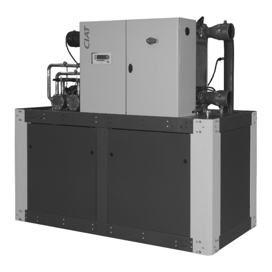
1 - INTRODUCTION DYNACIAT LG and LGP series water chillers are designed to meet the air conditioning and heating requirements of residential POWER and office buildings as well as the requirements of manufacturing processes, The DYNACIAT LG, LGP units are liquid chillers POWER with water cooled condensers which guarantee safe and reliable performance in the defined area of application. All the units are factory tested and checked. They are supplied with a full refrigerant load. These units meet standard EN 60-204 and standard EN378-2 as well as the following European directives: ■... -
Page 4: Receipt Of Goods
Please include the identification number in all ■ HP Maxi PSM/MOP: For the high pressure circuit: correspondence with CIAT. - HP. Maxi. = Maximum operating pressure in bar. - P S M / M O P = M a x i m u m s t a n d a r d p r e s s u r e i n b a r (SP according to PED 2014/68/EU). -
Page 5: Safety Instructions
4 - SAFETY INSTRUCTIONS To avoid any risk of accident during installation, start-up and adjustments, the following equipment specifics must be taken into account: ■ Pressurised refrigeration circuits ■ Presence of refrigerants ■ Presence of electrical voltage Only experienced and qualified persons may work on such equipment. The recommendations and instructions in this manual and on each drawing provided with the unit must be followed. In the case of units with pressure equipment or components, we recommend that you contact your professional organisation for information on the regulations that apply to operators or owners of pressure equipment or components. The characteristics of this equipment/these components are given on the name plate or in the regulatory documentation supplied with the products. -
Page 6: Handling And Positioning
8 - HANDLING AND POSITIONING To raise the unit, attach the slings to the designated handling holes. The data relating to the centre of gravity and the position of the anchorage points are given on the dimensional drawing. Detailed view of the anchorage point for handling DYNACIAT POWER Holes for handling Ø... -
Page 7: Location
9 - LOCATION 9.1 - Location of the unit 9.1.1 - Dimensions and ground mounting of the frame The frame may be affixed to the ground. (Mounts with studs not supplied by CIAT). The hardness is to be defined according to the unit's weight and centre of gravity. DYNACIAT POWER Ø 20,5 mm 0,5 m 0,5 m Free space to be maintained to allow sufficient room for maintenance of the unit. It is important that the units are installed with the necessary clearances. -
Page 8: Operating Limits
10 - OPERATING LIMITS 10.1 - Operating range The graph below represents the area of application (under full load) of the units. DYNACIAT 700 V to 2400 V POWER Glycol compulsory Evaporator outlet water temperature 10.2 - Limits DYNACIAT POWER Yes –... -
Page 9: Minimum/Maximum Water Flow Rates
10 - OPERATING LIMITS 10.4 - Minimum/maximum water flow rates The flow rates in the exchangers must be maintained between the values given below. DYNACIAT LG - LGP 700 V 800 V 900 V 1000 V 1100 V 1200 V 1400 V 1600 V 1800 V 2100 V 2400 V POWER min. m³/h Evaporator max. -
Page 10: Main Components Of The Refrigerating Circuit
Some of the sight glasses may turn yellow when the Repairs or modifications of any kind to the plate heat exchangers machine is powered off, as their sensitivity is are prohibited. CIAT only authorises replacement of the heat affected by the fluid temperature. exchanger by a qualified technician using original equipment. If the heat exchanger is replaced, this must be noted in the ... -
Page 11: Hydraulic Connections
13 - HYDRAULIC CONNECTIONS 13.1 - Diameters of the hydraulic and refrigeration connections DYNACIAT POWER LG – LGP DYNACIAT POWER 700 V 800 V 900 V 1000 V 1100 V 1200 V 1400 V 1600 V 1800 V 2100 V 2400 V DN 100 PN 16 - DN 150 PN 16 Chilled water inlet/outlet... -
Page 12: Flange/Victaulic Adapter Kit For Dynaciat Power (Option)
CIAT shall not If antifreeze is not added to the circuit and the unit be held liable for damage resulting from the use... -
Page 13: Glycol/Water-Mix Antifreeze Protection
14 - GLYCOL/WATER-MIX ANTIFREEZE PROTECTION The table and the curves below indicate the minimum percentages of glycol with which the system must be provided depending on the freezing point. The glycol concentration must protect the fluid at least 6°C below the water outlet temperature specified for the evaporator to allow correct setting of the minimum pressure controller at the evaporator. -
Page 14: Electrical Connections
Failure to do so will automatically void the CIAT warranty. Terminal X1 Wiring is to be sized by the installer to suit the characteristics of the installation site and comply with applicable regulations. - Page 15 15 - ELECTRICAL CONNECTIONS General fault alarm: Setpoint 1/setpoint 2 selector control Connector J6 (CPU) Connector J3 (CPU) Connect a “C2” contact to the terminals of the connector of the 230 V Alarm CPU board (high-quality polarity-free contact) ■ Contact open → setpoint 1 Remote control: Connect the unit's general fault reporting or ■ Contact closed → setpoint 2 alarm to the terminals on the unit's terminal strip (see wiring diagram).
-
Page 16: Control And Safety Devices
15 - ELECTRICAL CONNECTIONS NOTE: ■ Connection to be made on site by the customer, ■ Relay board(s) (option): ■ Precautions for connection. See manual for the regulator This board is installed in a cabinet in the machine room and the electrical diagram of the unit. and can remotely report on all the unit's operating states and faults by providing contacts which are potential-free Communication... -
Page 17: Phase Controller Kit
16 - CONTROL AND SAFETY DEVICES ■ Evaporator frost protection ■ Discharge sensor The evaporator is protected against freezing by two sensors: Each unit includes one discharge sensor per refrigerating circuit as standard. This sensor located on the discharge piping makes ■... -
Page 18: Location Of The Safety Sensors And Devices
16 - CONTROL AND SAFETY DEVICES 16.5 - Location of the safety sensors and devices 700 V to 1600 V with thermostatic expansion valves COILED IN THE CABINET CIRCUIT 1 CIRCUIT 2 OPTION Suction valves Discharge valves Inlet Differential pressure FIRE switch Outlet... - Page 19 16 - CONTROL AND SAFETY DEVICES DYNACIAT POWER 700 V to 1600 V with electronic expansion valves COILED IN THE CABINET Pressure- reducing Schrader regulator valve Pressure- reducing CIRCUIT 1 CIRCUIT 2 regulator OPTION Suction Schrader valves valve Discharge valves Inlet Differential pressure...
-
Page 20: Adjusting The Control And Safety Devices
16 - CONTROL AND SAFETY DEVICES 16.6 - Adjusting the control and safety devices Units Function Electrical symbol Settings Adjust the setpoint according to the outdoor Outdoor sensor temperature Chilled water inlet sensor Control of the unit on the water return Chilled water outlet manifold Unit control if controller on water outlet sensor... -
Page 21: Commissioning
17 - COMMISSIONING 17.1 - Commissioning Checks prior to system start-up: Always read this manual in full before attempting to commission the system. The system must be started and commissioned by a qualified Comply with applicable national regulations during testing and technician. installation. ■ The system must be charged with refrigerant and water flowing Before commissioning the system, carry out the following checks: in the exchangers when it is turned on and tested. ■... -
Page 22: Essential Points That Must Be Checked
17 - COMMISSIONING 17.2 - Essential points that must be checked Compressors: Refrigerant charge: Ensure that each compressor is rotating in the correct direction, The LG and LGP units are shipped with an exact charge of by checking that the discharge temperature rises quickly, the HP refrigerant. To make sure that the unit is filled with the correct increases and the LP drops. If it is rotating in the wrong direction, charge of refrigerant, perform the following checks circuit by the electric power supply is incorrectly wired (reversed phases). circuit with the system running at full capacity: To ensure rotation in the correct direction, swap two power supply ... -
Page 23: Technical And Electrical Specifications
18 - TECHNICAL AND ELECTRICAL SPECIFICATIONS DYNACIAT POWER LG - LGP 700 V 800 V 900 V 1000 V 1100 V 1200 V 1400 V 1600 V 1800 V 2100 V 2400 V Compressor Type Hermetic SCROLL (2900 rpm) Number Start-up mode Direct in line in series Refrigerant oil type... -
Page 24: Servicing And Maintenance
19 - SERVICING AND MAINTENANCE 19.1 - Operating readings Date/Time Suction pressure Intake temperature °C Compressor Condensing pressure Condensing temperature °C Discharge inlet temperature °C Liquid outlet temperature °C Water-cooled condenser Water inlet temperature °C Water outlet temperature °C Water inlet temperature °C Water outlet temperature °C... - Page 25 19 - SERVICING AND MAINTENANCE 19.2.2 - Noise Although halocarbon and hydrofluorocarbon refrigerants are not flammable, keep them away from open flames (e.g. It is also recommended that persons working near significant cigarettes, etc.), as temperatures of over 300°C cause their sources of noise wear ear protection. vapours to break down and form phosgene, hydrogen fluoride, ...
- Page 26 19 - SERVICING AND MAINTENANCE Annual checks 19.2.7 - Disassembling the compressor ■ Carry out the same inspections as during the monthly checks. The compressor is fastened to the platform by four dia. 8 mm screws. ■ Test the oil for contaminants: If acid, water or metal particles are detected in the oil, replace it in the corresponding circuit Do not tighten these compressor screws to a torque and the dryer.
-
Page 27: Ecodesign
(WEEE). Recommendations for disassembly ■ In France, CIAT has formed a partnership with ECOLOGIC ■ Use the original lifting equipment. for the collection and recovery of professional waste governed ■ Sort the components according to their material for recycling by European Directive WEEE 2012/19/EU. -
Page 28: Troubleshooting Operating Problems
22 - TROUBLESHOOTING OPERATING PROBLEMS Preliminary advice: ■ Faults detected by the safety devices are not necessarily caused by a sudden change in the measurement being monitored. ■ Taken regularly, readings should make it possible to anticipate future trips. ■ Perform the checks listed in the table below (next page) if you notice that a measurement deviates from its normal value and gradually moves closer to the safety limit. -
Page 29: Dynaciat Power Lg, Lgp Schematic Installation Diagram
23 - DYNACIAT LG, LGP SCHEMATIC INSTALLATION DIAGRAM POWER 23.1 - Cooling installation with drycooler DYNACIAT POWER Chilled water circuit Shut-off valve Water hoses (Compulsory on DYNACIAT) Recovery water circuit Temperature controller Thermowell Water filling Temperature controller Hydraulic 3-way valve Expansion vessel Air bleed Cleanable heat exchanger Control valve... -
Page 30: Heating Mode (Heating And Cooling)
23 - DYNACIAT LG, LGP SCHEMATIC INSTALLATION DIAGRAM POWER 23.3 - Heating mode (Heating and cooling) Chilled water or hot water circuit Shut-off valve Well discharge Water filling Air bleed valve Hydraulic valve Expansion vessel Water filter (compulsory) Cleanable exchanger Control valve Water hose (compulsory) Safety valve Drain Thermowell... - Page 32 The quality management system of this product’s assembly site has been certified in accordance with the requirements of the ISO 9001 standard (latest current version) after an assessment conducted by an authorized independent third party. The environmental management system of this product’s assembly site has been certified in accordance with the requirements of the ISO 14001 standard (latest current version) after an assessment conducted by an authorized independent third party.
Need help?
Do you have a question about the DYNACIAT POWER LG and is the answer not in the manual?
Questions and answers