Advertisement
Quick Links
NT777 MK2 AUTOPILOT INSTALLATION & CALIBRATION
NAVITRON SYSTEMS LTD
NT777 MK2 AUTOPILOT
INSTALLATION & OPERATION MANUAL
17 The Tanneries
Brockhampton Lane
Havant, Hants, U.K. PO9 1JB
Registered in England No. 2607869
Tel: (023) 9249 8740
Int. Code: +44 23
Email: sales@navitron.co.uk
Web: www.navitron.co.uk
1123/2
Advertisement

Related Manuals for Navitron NT777 MK2

Summary of Contents for Navitron NT777 MK2
- Page 1 NT777 MK2 AUTOPILOT INSTALLATION & CALIBRATION NAVITRON SYSTEMS LTD NT777 MK2 AUTOPILOT INSTALLATION & OPERATION MANUAL 17 The Tanneries Brockhampton Lane Havant, Hants, U.K. PO9 1JB Registered in England No. 2607869 Tel: (023) 9249 8740 Int. Code: +44 23 Email: sales@navitron.co.uk Web: www.navitron.co.uk...
- Page 2 NT777 MK2 AUTOPILOT INSTALLATION & CALIBRATION - Contents - Functional Description of Standard Units. Standard Unit Dimensions and Installation. Standard Unit Cables and Connections. Installation Adjustments and Alongside Trials. Application Notes (Including Proprietary Remote Power Steer Connections). Optional Equipment Installation.
- Page 3 In addition to the PID intelligence inherent in the NT777 MK2 control electronics, the potential diversity of steering systems types is also accommodated by the inclusion of automatic and manual installation adjustments which easily enable Autopilot demands to be matched to individual steering system characteristics.
- Page 4 NT777 MK2 AUTOPILOT INSTALLATION & CALIBRATION Typical NT777 MK2 Autopilot Installation...
- Page 5 NT777 MK2 AUTOPILOT INSTALLATION & CALIBRATION Autopilot System Input / Output Specifications Outputs:- Inputs:- 18 – 40Vdc NMEA 0183 / IEC 61162-1 or -2 Heading / Rudder Position Main Supply Voltage Range Data Output Port (Isolated RS422) Single / Backup Supply 11–...
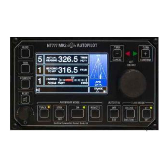
- Page 6 The Heading Sensor Coil. The Compass Junction Box. The Rudder Reference Unit. 1.1 NT777 MK2 Control Unit (FIG 1.1). The control unit is the principal element from the viewpoint of the operator and contains the electronics associated with the display drive circuitry and all operator control communications with the distribution unit.
- Page 7 NT777 MK2 AUTOPILOT INSTALLATION & CALIBRATION 1.2 NT777 MK2 Distribution Unit. This unit is the central distribution point of the NT777 MK2 Autopilot system since, in addition to all of the electronic control intelligence and associated voltage regulation etc. it houses the solenoid switching stages, both aspects of which are internally fuse protected at 2A and 5A respectively.
- Page 8 NT777 MK2 AUTOPILOT INSTALLATION & CALIBRATION FIG 1.2.2 NT777 MK2 Distribution Unit. For further Distribution Unit information refer as follows: - Installation Section 2.2 Connection Section 3.1...
- Page 9 NT777 MK2 AUTOPILOT INSTALLATION & CALIBRATION 1.3 The Heading Sensor Coil Type HSC2 (FIG 1.3). This unit contains two main sets of windings which, when installed above or below and in close proximity to the proprietary steering compass produces (in conjunction with the magnetic flux of the steering compass) an electronic heading reference.
- Page 10 NT777 MK2 AUTOPILOT INSTALLATION & CALIBRATION 1.5 The Rudder Reference Unit (FIG 1.5). This unit incorporates a conductive plastic potentiometer and two limit switches (Port and Starboard) with associated cams. The potentiometer continuously signals the precise angular position and velocity of the rudder to the control unit whilst the limit switches are adjusted and set during installation to ensure that the rudder is not driven unnecessarily to its mechanical extremes.
- Page 11 The Rudder Reference Unit. Installation Note – Radio Frequency Interference (RFI). All Navitron Autopilot systems exhibit high levels of RFI rejection (MF, HF & VHF) by virtue of careful decoupling and suppression measures exercised as a standard Navitron Systems design function and are compliant with the statutory requirements of EN60945 (IEC60945).
- Page 12 NT777 MK2 AUTOPILOT INSTALLATION & CALIBRATION FIG 2.1 NT777 MK2 Control Unit Outline Dimensions & Mounting Details. 2.2 The NT777 MK2 Distribution Unit Installation. Compass Safe Distance 0.4m. The distribution unit is not suitable for external location and must be installed in an enclosed wheelhouse location.
- Page 13 NT777 MK2 AUTOPILOT INSTALLATION & CALIBRATION Fig 2.2 NT777 MK2 Distribution Unit Outline Dimensions. 2.3 The Heading Sensor Coil type HSC2. Navitron Heading Sensor Coil type HSC2 contains encapsulated electronic components requiring 6 connections and is factory fitted with a 1.5 metre length of 6-core cable accordingly.
- Page 14 NT777 MK2 AUTOPILOT INSTALLATION & CALIBRATION 2.3 The Heading Sensor Coil type HSC2 (Continued). Later calibration may determine that a non-magnetic spacer must be introduced between the HSC2 and its mounting bracket to increase the distance between the HSC2 and the compass magnet.
- Page 15 NT777 MK2 AUTOPILOT INSTALLATION & CALIBRATION 2.5 Rudder Reference Unit Installation (FIG 2.5). The Rudder Reference Unit should be located and secured in the steering compartment, or tiller flat, such that the Reference Unit arm (X) may be mechanically coupled to the Rudder arm (Y) to provide a linear angular relationship between Rudder arm and Reference Unit arm movements (see Figure 2.5.1).
- Page 16 NT777 MK2 AUTOPILOT INSTALLATION & CALIBRATION 2.5 Rudder Reference Unit Installation (Continued). NOTE: The relative arm lengths of X and Y (the X: Y ratio) should be nominally 1.5:1 and angles between arms X and Y and the connecting rod should be 90° when the rudder is amidships.
- Page 17 RF associated cables. Commensurate with the use of screened cables, earth points are fitted within the NT777 MK2 Control & Distribution Units adjacent to the cable entry glands to provide screen terminations for all cables entering. In addition, an external 4mm dia earth stud is available on both units and must be connected to the Ships earth via a flat braid or earth tape.
- Page 18 4 Core twin twisted 0.22mm 7/0.2mm pair screened pair screened 2 Core twin twisted 0.22mm 7/0.2mm pair screened NOTE: The NT777 MK2 DB accepts dual 24Vdc (18-40Vdc) electronics power supplies or a single 12Vdc / 24Vdc (11-40Vdc) supply. See Section 3.1.1 for details.
- Page 19 NT777 MK2 AUTOPILOT INSTALLATION & CALIBRATION Fig 3.1 NT777 MK2 System Connection details.
- Page 20 Unit and two cable gland entries are located at the rear of the Control Unit case. The terminal connectors within the NT777 MK2 Control Unit are accessed by removal of 6 x M3 slotted screws, which are located on the Control Unit rear gland plate assembly.
- Page 21 3.1.1 Single / Dual Electronics Power Supplies. The NT777 MK2 DB accepts dual 24Vdc (18-40Vdc) electronics power supplies or a single 12Vdc / 24Vdc (11-40Vdc) supply. See Fig 3.1.1.1 & 3.1.1.2 for details.
- Page 22 NT777 MK2 AUTOPILOT INSTALLATION & CALIBRATION Heading Sensor Coil (Type HSC2) to Compass Junction Box Connections. All Connections to the Heading Sensor are factory fitted thus only the Compass Junction Box connections are relevant (See FIG 3.2). When routing the Heading Sensor Cable from the magnetic compass ensure that the compass is unrestricted in gymballing.
- Page 23 NT777 MK2 AUTOPILOT INSTALLATION & CALIBRATION 3.3 Rudder Reference Unit Connections (FIG 3.3). There are two connection conditions for the Rudder Reference Unit. The correct condition must be identified by reference to the direction of movement of the Rudder Reference Unit arm when the Rudder moves to Starboard.
- Page 24 NT777 MK2 AUTOPILOT INSTALLATION & CALIBRATION Distribution Unit Yellow White Cable No. 15 (N° 3 Cable) Black Green Blue STBD FIG 3.3.2 Rudder Reference Unit Connections – CONDITION 2. Further adjustment may be required at the Rudder Reference Unit (Limit switch adjustment) in accordance with Section 4.1.
- Page 25 NT777 MK2 AUTOPILOT INSTALLATION & CALIBRATION 3.4 Port & Starboard Solenoid Connections (Continued). * See Section 3.4.3 for details of suppression components. Fig 3.4.1 Common Positive Solenoids * See Section 3.4.3 for details of suppression components. Fig 3.4.2 Common Negative Solenoids...
- Page 26 $xxRMB & Error” correction mode. over the ground, speed over $xxRMC Automatic course change at ground & range waypoint arrival. destination. The NT777 MK2 will also accept "Variation" data contained in the $xxRMC sentence. This data will be used when necessary.
- Page 27 3.6 Optional NMEA 0183 Output Connections. (2 Core screened cable required). The NT777 MK2 Autopilot generates and outputs serial heading and rate of turn information (for use by radars, track plotters etc.) conforming to the NMEA 0183 protocol. The available update rates are as follows:-...
- Page 28 N2K backbone. The lead comprises a standard 5 pin 12mm circular connector pre-wired with 2m of cable. The NT777 MK2 DB can input / receive heading, rate of turn and track data via the N2K interface and can also output / transmit heading, rate of turn and rudder angle data to other users on the N2K interface.
- Page 29 NT777 MK2 AUTOPILOT INSTALLATION & CALIBRATION 3.9 Optional Watch Alarm Connections. (Terminal N°s 18 - 23). The NT777 MK2 DB provides connections to support NT990 BNWAS RST units which are used to provide remote acknowledgement of the watch alarm. See Section 6.10 for mounting and connection details.
- Page 30 NT777 MK2 AUTOPILOT INSTALLATION & CALIBRATION Section 4: Installation Adjustment & Alongside Trials Essential NT777 MK2 Control Unit Address Reprogramming. Limit Switch Adjustment. Autopilot and Solenoid Power Supply. Feedback Phase Connections. Set Up Menu. To enter the Set Up Menu.
- Page 31 NT777 MK2 AUTOPILOT INSTALLATION & CALIBRATION 4.26 NMEA Channel 1 Input/Output Baud Rate. 4.27 NMEA Chanel 1 Output Update Rate. 4.28 NMEA Channel 2 Input Baud Rate. 4.29 NMEA 0183 / N2K Track Data Type. 4.30 Track Data Baud Rate.
- Page 32 The actual address setting (NULL, 1, 2, or 3) is always confirmed at power up via the start up screen display:- To Change the NT777 MK2 Control Unit Address from NULL to 1, 2 or 3. Ensure that the Autopilot electronics Isolator is ON and that the Solenoid Supply Isolator is off.
- Page 33 In addition to the mechanically operated normally closed limit switches housed within the Rudder Reference Unit ‘electronic limit switch’ facilities are installation programmable via the NT777 MK2 Control Unit Set up menu. Where practicable, it is recommended that the mechanical switches are employed and adjusted accordingly as simple failsafe devices.
- Page 34 NT777 MK2 AUTOPILOT INSTALLATION & CALIBRATION 4.1 Limit Switch Adjustment (Continued). Adjust and lock the appropriate cam (M3 socket set screw) such that its associated limit switch is depressed. (An audible click will signal when the switch is depressed and rendered open circuit).
- Page 35 3.3.2) 4.4 Set Up Menu. The NT777 MK2 is equipped with a comprehensive interactive Set Up Menu which allows all Autopilot Set Up parameters to be accessed and adjusted. The Menu can only be entered from the “Standby” mode and, in a multi control unit system, from the control unit currently active.
- Page 36 NT777 MK2 AUTOPILOT INSTALLATION & CALIBRATION 4.5 To enter the Set Up Menu:- Simultaneously press the “CANCEL” and “CONFIRM” keys for 5 seconds after which the NT777 MK2 display will show a table of Set Up parameters and will highlight the parameter currently selected.
- Page 37 NT777 MK2 AUTOPILOT INSTALLATION & CALIBRATION COIL HEADING XXX.X° DEGREES COIL SIGNAL XXXX INFO ONLY HDG PRIORITY NMEA (default value) COIL, NMEA OR N2K CHAN1 ( “ “ ) NMEA CHANNEL PRI CHAN1 OR CHAN2 MAG/TRUE ( “ “ )
- Page 38 NT777 MK2 AUTOPILOT INSTALLATION & CALIBRATION 4.6 DISPLAY INVERT. Note: The CONTRAST ADJUST parameter is not used in the NT777 MK2 Control Unit. Move the blue bar to parameter 2 DISPLAY INVERT. Two display modes are possible allowing the operator to select as required.
- Page 39 NT777 MK2 AUTOPILOT INSTALLATION & CALIBRATION 4.10 AUTOTRIM MODE. The Autotrim (sometimes known as Automatic Permanent Helm – APH) function allows the Autopilot to monitor any long term difference between the Autopilot course set and the actual heading steered due to adverse windage conditions/vessel trim etc.
- Page 40 4.17 RUDD. POSN. SENS. (Rudder Position Sensitivity) Rudder positioning accuracy and stability is ultimately dependant upon the integrity of the steering system (mechanical wear/backlash etc.). The NT777 MK2 is programmable to 4 levels of positioning sensitivity as follows:- 0.75 , 1.25 , 1.75...
- Page 41 NT777 MK2 AUTOPILOT INSTALLATION & CALIBRATION 4.18 AUTO STABILITY. WARNING: Calibration of this parameter involves a sequence of automatic rudder movements which allows the Autopilot software to “measure” unnecessary rudder activity (undershoot/ overshoot) and to compensate accordingly to ensure that the steering system overall is stable and “critically damped”.
- Page 42 (+/-). 4.23 NMEA CHANNEL PRI. (PRIORITY). The NT777 MK2 is equipped with two NMEA heading input ports identified as CHAN1 and CHAN2. When both channels are connected to independent NMEA heading data sources, one or other of the channels can be specified as the priority input.
- Page 43 Select 4800 or 38K4 BD as required via rotation of the illum. knob (+/-). 4.29 TRACK DATA TYPE. Track data can be received by the NT777 MK2 via the NMEA 0183 input or via the N2K interface. 0183 (NMEA 0183) is in most cases the sentence type that will be required and can provide a number of sentence types (APA, APB, RMB, HTC etc.) at...
- Page 44 4.31 XTE CLOSING ANGL. (XTE Closing Angle) Automatic assessment of the heading offset required to compensate for Set and Drift finally allows the NT777 MK2 to return the vessel to the rhumbline (track) required by automatically ordering a heading change of 5...
- Page 45 When there is a departure from the Autopilot Set Course in excess of the amount specified, the Off Course Alarm will sound and can be cancelled by operation of the NT777 MK2 RESET key. In the event that a large course change has been ordered which may take significant time, further alarms during the turn can be avoided by programming the alarm reinstatement time.
- Page 46 NT777 MK2 AUTOPILOT INSTALLATION & CALIBRATION 4.39 CONTROL UNIT ADDR. (Control Unit Identity) The NT777 MK2 Autopilot System can employ a maximum of three (3) Control Units which, for Distribution Unit software purposes, must be uniquely identified as No. 1, 2 or 3. (Control units in the same system must not have the same identity number).
- Page 47 ALARM POWER SUPPLY TYPE SINGLE The NT777 MK2 must be in Set Up Mode – simultaneously press CANCEL and COMFIRM keys for 5 seconds confirmed by Set Up parameters in display. Use the SET COURSE knob to scroll down to parameter 36 FACTORY SET.
- Page 48 There can be multiple devices on the N2K bus that transmit the actual vessel heading therefore the priority source of heading data must be specified. The NT777 MK2 DB is capable of listing up to 4 device (node) addresses that are transmitting heading data. When first selecting the “N2K HDG SRC”...
- Page 49 GPS data must be specified. The NT777 MK2 DB is capable of listing up to 4 device (node) addresses that are transmitting GPS data. When first selecting the “N2K GPS SRC”...
- Page 50 NT777 MK2 AUTOPILOT INSTALLATION & CALIBRATION Section 5: Application Notes. Port and Stbd Solenoid Switching Stages. The Rudder Reference (Feedback) Potentiometer. Auxiliary Relay. Proprietary Remote Power Steer. 5.4.1 Follow Up and Non Follow Up Operating Conditions. 5.4.2 Non Follow Up Mode.
- Page 51 NT777 MK2 AUTOPILOT INSTALLATION & CALIBRATION Fig 5.1.1 Common positive Solenoid Connections. Fig 5.1.2 Common Negative Solenoid Connections.
- Page 52 Track Angle (90°) Ref. Arm Length (1.5) Example 2: A standard NT777 MK2 series Control Unit installed to a 2:1 reduction gear driven alternative potentiometer shaft and based on the following assumptions: - Coupling (gear) ratio (rudder: pot shaft) = 2:1 Pot track angle 270°...
- Page 53 The relay contacts are volt free and rated 3A @ 30Vdc for connection to external services as required. Relay contact response to NT777 MK2 Autopilot operating modes are shown below but it should be noted that remote power steer demands will also activate the Auxiliary relay in the “STANDBY”...
- Page 54 NT777 MK2 AUTOPILOT INSTALLATION & CALIBRATION Proprietary Remote Power Steer Connections. All Navitron Autopilots are internally equipped to accept both Follow Up and Non Follow Up signal inputs from virtually any type of potentiometric (Follow Up) or Jog Switch (Non Follow Up) remote station. Facilities are also included for remote ‘Dodge’...
- Page 55 Remote Dodge operation is available when the Autopilot is in the ON mode provided the proprietary Remote Station ON/OFF switch is set to ‘ON’ The ‘ON’ condition is confirmed at the NT777 MK2 Autopilot Control Unit by display indication of the ‘REM DODGE’ and is accompanied by an audible ‘bleep’...
- Page 56 NT777 MK2 AUTOPILOT INSTALLATION & CALIBRATION FIG 5.4.2 Non Follow Up Remote Steer Connections. FIG 5.4.3 Full Follow Up Remote Steer Connections. FIG 5.4.4 Dodge Mode Remote Steer Connections. Refer to table A for R1 values.
- Page 57 NT777 MK2 AUTOPILOT INSTALLATION & CALIBRATION Section 6: Optional Equipment Installation. Watch Alarm Type NT920WA. Non Follow Up Power Steer Type NT920NFU. Follow Up Power Steer Type NT920FU. Follow Up Power Steer Type NT990FU. Hand Held Remote Steer Type NT921HRC.
- Page 58 NT777 MK2 AUTOPILOT INSTALLATION & CALIBRATION 6.1 Watch Alarm Type NT920WA. Whilst the NT777 MK2 Autopilot System is equipped with an integral watch Alarm programmable between 3 and 12 minutes, there may be occasions when the NT920 Watch Alarm (NT920WA) is also required for duty in conjunction with the Autopilot.
- Page 59 NT777 MK2 AUTOPILOT INSTALLATION & CALIBRATION 6.1 Watch Alarm Type NT920WA (Continued). The unit may be panel or foot mounted as required with allowance made for cable access to the cable entry glands at the rear of the unit. Outline dimensions and mounting details are shown in FIG 6.1.1 Cable and connection details are shown in FIG 6.1.2...
- Page 60 NT777 MK2 AUTOPILOT INSTALLATION & CALIBRATION FIG 6.1.2 - NT920WA Watch Alarm Cable and Connection Details.
- Page 61 Non Follow Up Mode is made available when the Autopilot is in STANDBY. Both DODGE and NFU Modes are only available if the NT777 MK2 Control Unit REMOTE switch is enabled (corner LED on). The Dodge Function...
- Page 62 NT777 MK2 AUTOPILOT INSTALLATION & CALIBRATION 6.2 NT920NFU (Navitron Non Follow Up Power Steer – & Dodge Control) Continued. Subsequent movement of the NT920NFU Jog lever to the Right (Stbd) or Left (Port) will produce corresponding rudder movement to hard over rudder if the Jog lever is held right or left of the central position for a prolonged period.
- Page 63 NT777 MK2 AUTOPILOT INSTALLATION & CALIBRATION FIG 6.2.1. – NT920NFU and NT920FU Outline Dimensions and Mounting Details.
- Page 64 NT777 MK2 AUTOPILOT INSTALLATION & CALIBRATION * VR1 is adjusted in the DODGE mode to limit the angle of rudder applied (5 – 30° range) FIG 6.2.2. – NT920NFU Cable and Connection Details.
- Page 65 The NT920FU enables permanent (POWER STEER) heading changes to be ordered at locations remote from the Autopilot Control Unit and can be selected when the NT777 MK2 Autopilot is ON and Remote Controls are enabled via the NT777 MK2 Control Unit REMOTE key (corner LED on).
- Page 66 NT777 MK2 AUTOPILOT INSTALLATION & CALIBRATION NT920FU (Navitron Follow Up Power Steer) Continued. NT920FU Installation: - Compass Safe Distance – 0.3m The NT920FU is not suitable for unprotected external location and should be installed in an enclosed bridge or wheelhouse in a position commensurate with the field of vision required to safely undertake remote steering operations.
- Page 67 NT777 MK2 AUTOPILOT INSTALLATION & CALIBRATION FIG 6.3.1. – NT920FU Cable and Connection Details.
- Page 68 Set Course Display will follow any changes in the vessel’s heading, thus a “steer on lock on” function is provided. Remote Power Steer is available when the NT777 MK2 Autopilot System is On and Remote stations etc. are enabled via the Control unit REMOTE key (corner LED on).
- Page 69 NT777 MK2 AUTOPILOT INSTALLATION & CALIBRATION FIG 6.4.1. – NT990FU Outline Dimensions and Mounting Details.
- Page 70 NT777 MK2 AUTOPILOT INSTALLATION & CALIBRATION FIG 6.4.2. – NT990FU Cable and Connection Details...
- Page 71 The NT921HRC enables permanent (POWER STEER) heading changes to be ordered at locations remote from the Autopilot Control Unit and can be selected when the NT777 MK2 Autopilot System is ON and Remotes are enabled via the Control Unit REMOTE key (corner LED on).
- Page 72 NT777 MK2 AUTOPILOT INSTALLATION & CALIBRATION 6.5 NT921HRC (Navitron Hand Held Follow Up Power Steer) Continued. NT921HRC Installation: - A 1 metre (6 metre extended) length of trailing cable is fitted to the HRC for connection to the NT777 MK2 Distribution Unit.
- Page 73 NT777 MK2 AUTOPILOT INSTALLATION & CALIBRATION FIG 6.5.1. – NT921HRC Connection and Calibration Reference.
- Page 74 NT777 MK2 AUTOPILOT INSTALLATION & CALIBRATION 6.6 Navitron Rudder Angle Indicator Type NT920RAI. Navitron rudder angle indicators may be configured for single or multi head display as add on components to all Navitron Autopilot types. All indicator heads (type NT920RAI) are electrically identical (no master/slave distinction) providing complete interchangeability.
- Page 75 NT777 MK2 AUTOPILOT INSTALLATION & CALIBRATION FIG 6.6.1 – NT920RAI Outline and Mounting Dimensions...
- Page 76 NT777 MK2 AUTOPILOT INSTALLATION & CALIBRATION FIG 6.6.2 – NT920RAI (PM) Pod Outline and Mounting Dimensions...
- Page 77 NT777 MK2 AUTOPILOT INSTALLATION & CALIBRATION...
- Page 78 6.7 Heading Repeater Type NT920DHR MKII. Navitron Digital Heading Repeater type NT920DHR/2 is used to display NMEA 0183 heading data received from the NT777 MK2 Autopilot (and other Navitron / proprietary Heading data sources). Ruggedly engineered and suitable for bracket or console mounting in...
- Page 79 NT777 MK2 AUTOPILOT INSTALLATION & CALIBRATION FIG 6.7.1 – NT920DHR/2 Outline Dimensions and Mounting Details...
- Page 80 NT777 MK2 AUTOPILOT INSTALLATION & CALIBRATION FIG 6.7.2 - NT920DHR/2 Cable and Connection Details Term No. Service Core Colour Cable Type 2 core 7/0.2mm twisted Blue pair screened NMEA0183 input Screen Brown 2 Core 16/0.2mm 11-40Vdc Ship’s supply Blue...
- Page 81 NT777 MK2 AUTOPILOT INSTALLATION & CALIBRATION 6.7 NT920DHR/2 Operation. When power is applied to the unit a display segment test (“8.8:8.8”) will be performed followed by the software version number (i.e. “1.0”). If a valid NMEA0183 heading sentence is being received the source will be shown immediately followed by the actual heading.
- Page 82 NT777 MK2 AUTOPILOT INSTALLATION & CALIBRATION 6.7 NT920DHR/2 Operation (Continued). “Hdg” NMEA0183 $XXHDG heading data is being used as the data source. The displayed heading will be corrected for variation and deviation if the data is available in the received sentence.
- Page 83 6.8 Heading Repeater Type NT920AHR MK2. The NT920AHR MK2 (Analogue Heading Repeater) provides a 120mm diameter rotating card display of current heading when the NT777 MK2 Autopilot system is powered up in any operating mode provided supply voltage is also separately available (11-40Vdc) to the AHR.
- Page 84 NT777 MK2 AUTOPILOT INSTALLATION & CALIBRATION 6.8 Heading Repeater Type NT920AHR (Continued). HSC = 3 series of 5 bleeps over 5 seconds The foregoing audible signal following automatic alignment confirms normal operation and the sentence type on which operation is based.
- Page 85 NT777 MK2 AUTOPILOT INSTALLATION & CALIBRATION FIG 6.8.1 – NT920AHR MK2 Outline Dimensions & Mounting Details...
- Page 86 NT777 MK2 AUTOPILOT INSTALLATION & CALIBRATION FIG 6.8.2 – NT920AHR MK2 Cable and Connection Details FIG 6.8.3 – NT920AHR MK2...
- Page 87 URB and are link selectable dependent on supply voltage type (AC or DC). Relay 3: - The URB power up relay is energised when the NT777 MK2 Autopilot is switched ON (Autopilot engaged). Relay 4: - Offers a normally open contact (rated 240V/2A AC), which closes in the event of solenoid main power failure to provide a switchline for an external alarm if required.
- Page 88 Compass Safe Distance – 1.5m The NT920URB should be installed in a dry internal location which is convenient to accept a 4 core cable from the NT777 MK2 Distribution Unit and the high voltage supply and solenoid cables. Outline dimensions and mounting details are shown in FIG 6.9.3.
- Page 89 NT777 MK2 AUTOPILOT INSTALLATION & CALIBRATION 6.9 Universal Relay Box Type NT920URB (Continued). FIG 6.9.2 – NT920URB P.C.B Layout FIG 6.9.3 – NT920URB Case Outline & Mounting Dimensions...
- Page 90 6.10 Optional NT990 BNWAS RST Units. Compass Safe Distance – 0.5m. The NT777 MK2 DB provides connections to support NT990 BNWAS RST units which are used to provide remote acknowledgement of the watch alarm. The NT990 BNWAS Reset unit is suitable for mounting in Wheelhouse and Bridge Wing locations in positions which are visible and readily accessible to the OOW.
- Page 91 NT777 MK2 AUTOPILOT INSTALLATION & CALIBRATION 6.10 Optional NT990 BNWAS RST Units (Continued). FIG 6.10.1 Reset Unit Outline Dimensions. Four mounting holes are provided outside of the sealing gasket and are exposed when the Remote Reset Unit lid is removed.
- Page 92 NT777 MK2 AUTOPILOT INSTALLATION & CALIBRATION Section 7.0: Operator Controls, Working limits and Sea Trials. Operator Controls, Working Limits and Displays Defined: - Autopilot Standby/OFF Key & Modes. The Autopilot ON Key/Mode. Rudder Control. Yaw Control. Counter Rudder Control. The Illumination Control.
- Page 93 NT777 MK2 AUTOPILOT INSTALLATION & CALIBRATION Section 7.0: Operator Controls, Working limits and Sea Trials. 7.20 Optimising The Rudder Control Setting. 7.21 The Rudder Control Band (Loop Gain Adjustment). 7.22 Autotrim (APH) Assessment. Manual cancellation of Trim. Manual Reset of Trim.
- Page 94 NT777 MK2 AUTOPILOT INSTALLATION & CALIBRATION 7.36 Magnetic Deviation. Auto Deviation Correction. (ii) Manual deviation Correction. (iii) Resetting (Clearing) Deviation Correction. 7.37 To Adjust Set Working Limits. Rudder Limit (ii) OCA Trip Adjustment. (iii) Watch Alarm Time. (iv) Dodge Angle.
- Page 95 ON key to engage the Autopilot System. 7.2 The Autopilot ON Key/Mode. The NT777 MK2 Autopilot can only be switched on via the Standby condition thus switching directly from Off to On is not possible. With the Standby LED on and the display active, press the ON keypad to engage.
- Page 96 NT777 MK2 AUTOPILOT INSTALLATION & CALIBRATION 7.2 The Autopilot ON Key. (Continued). An illuminated LED in the Autopilot Mode ON keypad confirms the operational status of the steering mode which is also “written” at the bottom of the Control Unit Display as “AUTO” etc. as appropriate.
- Page 97 7.7 The “Set Working Limits” Facility. Certain NT777 MK2 Autopilot functions are isolated from the main control panel to prevent inadvertent/unauthorised change but these aspects can be programmed/altered via access to the “Set Working Limits” facility which...
- Page 98 7.9 The Track Key. Track Steering operation is only possible when the Autopilot System is engaged (NT777 MK2 ON mode) and Track Steer data is available to the Autopilot from an external source such as GPS, Track Plotter or Track Steering System etc.
- Page 99 7.31 refers. 7.15 The NT777 MK2 Operational Display. The NT777 MK2 display is a programmable device which can be adjusted for Positive or Negative mode imaging via the Set Up menu. Four display formats exist of which two show Set Up parameters:- Main Set Up (42 parameters) ………………Section 4.4 refers.
- Page 100 NT777 MK2 AUTOPILOT INSTALLATION & CALIBRATION 7.16 Sea Trials. All necessary Set Up parameters and installation procedures should now have been completed in accordance with section 4. Check that the Autopilot Isolators are ON. (ii) Press the OFF/STBY key to enter the Standby mode.
- Page 101 NT777 MK2 AUTOPILOT INSTALLATION & CALIBRATION 7.18 Autopilot Engagement. Manually steer the vessel dead ahead at normal/typical operating speed with operator control settings as follows:- Rudder …….. 5 (ii) Yaw ………... 1 (iii) Counter ……. 1 Rudder Limit – default value 30° - Enter the “Set Working Limits” menu by pressing the RESET key for 5 seconds.
- Page 102 NT777 MK2 AUTOPILOT INSTALLATION & CALIBRATION 7.19 Initial Course Keeping Performance (Control of Heading). Provided the Autopilot YAW control is set to N°1 (minimum Yaw) corrective rudder will be demanded and applied by the Autopilot system for any short term yaw angle in excess of 0.7 degree*.
- Page 103 NT777 MK2 AUTOPILOT INSTALLATION & CALIBRATION 7.20 Optimising the Rudder Control Setting. The RUDDER control provides the operator with the means to increase or decrease the angle of rudder applied in relation to course error and should be adjusted to provide positive correction of Yaw without oversteer (Section 7.19 refers).
- Page 104 NT777 MK2 AUTOPILOT INSTALLATION & CALIBRATION 7.21 Loop Gain Adjustment. (Continued). Loop Gain Calibration. Switch the Autopilot to STANDBY and enter the Set Up Menu per section 4.4. (Vessel now under manual steering control). (ii) Use the Autopilot Set Course knob to scroll through the Set Up parameters until ‘LOOP GAIN’...
- Page 105 NT777 MK2 AUTOPILOT INSTALLATION & CALIBRATION 7.22 Seagoing Autotrim (APH) Assessment (Continued). APH timing periods of less than 200 seconds (3.3 minutes) are likely to degrade Autopilot steering performance on vessels other than high- speed craft with planing/semi planing hull forms. Timing periods greater than 300 seconds may benefit larger ocean going displacement vessels subject to seagoing appraisal.
- Page 106 NT777 MK2 AUTOPILOT INSTALLATION & CALIBRATION 7.22 Seagoing Autotrim (APH) Assessment (Continued). Manual Reset of Autotrim (APH) Rudder Offset. A permanent Helm Offset angle, which is correct on an existing heading, may prove to be totally incorrect immediately after shooting a trawl etc. or on a new heading particularly when large course changes are ordered.
- Page 107 Increase time constant * NOTE: Unnecessary reduction of time constant can degrade overall steering performance. If in doubt consult Navitron Systems Ltd. To Alter the APH Time Constant: - The APH time constant is accessed via the Setup Menu: - Set the Autopilot to STANDBY and enter the Set Up Menu per section 4.4.
- Page 108 NT777 MK2 AUTOPILOT INSTALLATION & CALIBRATION 7.24 Evaluating/Altering the Autotrim (APH) Time Constant (Continued). (iv) Exit the Set Up Menu per section 4.47. 7.25 Evaluating the Counter Rudder Setting. The Autopilot Counter rudder function continuously monitors the rate of change of heading (Rate of Turn) of the vessel and is principally responsible for the application of ‘Counter’...
- Page 109 NT777 MK2 AUTOPILOT INSTALLATION & CALIBRATION 7.25 Evaluating the Counter Rudder Setting (Continued). To increase / decrease the Counter Rudder value: - Set the Autopilot to STANDBY or ON and press the ‘Counter’ (iv) key. Rotate the illum. control (+/-) to increase or decrease the highlighted ‘COUNTER’...
- Page 110 NT777 MK2 AUTOPILOT INSTALLATION & CALIBRATION 7.26 Optimising the YAW Control Setting (Continued). As a general rule, the Yaw control should be set at the lowest number that provides the required course keeping sensitivity and ‘straight wake’ performance but avoids unnecessary rudder movements in response to natural Yaw.
- Page 111 NT777 MK2 AUTOPILOT INSTALLATION & CALIBRATION 7.27 The Autopilot Course Selector. (Set Course Knob) (Continued). Subsequent Heading (Course) Alteration. (ii) Turning the Set Course knob CLOCKWISE will be confirmed by the SET COURSE display and will order a vessel course change to STARBOARD.
- Page 112 NT777 MK2 AUTOPILOT INSTALLATION & CALIBRATION 7.28 The ±1 / ±5 Key Function. Turn modes of three types can be selected in readiness for turn execution by single keypad operation. (See sections 7.29 and 7.30). The ±1 / ±5 key selection is confirmed by the illuminated corner LED and...
- Page 113 NT777 MK2 AUTOPILOT INSTALLATION & CALIBRATION 7.29 The Dodge Key Function(Continued). When the TURN (-) or TURN (+) key is pressed, the offset angle is immediately executed and the red/green rudder demand chevrons flash accompanied by an audible “bleep” as a constant reminder that a DODGE manoeuvre is in progress.
- Page 114 NT777 MK2 AUTOPILOT INSTALLATION & CALIBRATION 7.31 The Cancel and Confirm Key Functions. These keys act mainly as “back ups” to Autopilot course changes which may be operator or automatically induced as follows:- Set Course knob rotation (section 7.27). (ii) Custom key operation (section 7.30).
- Page 115 NT777 MK2 AUTOPILOT INSTALLATION & CALIBRATION 7.33 The Remote Key Function. NT777 MK2 Autopilot Systems may be installed with up to a maximum of three Control Units – one of which may be designated as the “master” unit. In this case, the other (subordinate) units will require “permission” from the “master”...
- Page 116 (i) Combined Cross Track Error/Bearing to Waypoint mode (BER). Provided Cross Track error, Bearing Origin to Destination and Bearing to Waypoint data is received from the GPS or Track Plotter the NT777 MK2 will steer to multiple waypoints & correct for cross track error (see (ii) below for CTE correction details) to keep the vessel on the intended track.
- Page 117 GPS/Plotter etc. and a Track (rhumbline) to desired way point established, any departure (right or left of the rhumbline) is received by the NT777 MK2 Autopilot via NMEA data (APA, APB, XTE etc.) The CTE data received is processed within the Autopilot and applied (after computation) as a heading offset resulting in automatic correction of CTE to maintain the vessel on the specified track.
- Page 118 7.34 Cross Track Error Mode (XTE) (Continued). NOTE: Once the cross track error “fine” mode has been set it will not revert to “standard” mode until the NT777 MK2 Distribution unit is powered down and back up. Cross track error “fine” mode is indicated by the cross track error value (in the track display area) being shown in 0.001nm resolution.
- Page 119 NT777 MK2 AUTOPILOT INSTALLATION & CALIBRATION 7.34 Cross Track Error Mode (XTE) (Continued). Unless subsequent CTE data received confirms that the vessel is closing to the track, further 3° heading changes will then be automatically ordered until the vessel is parallel. Once determined as parallel to track, a further 5°...
- Page 120 7.34 Track Mode. (Continued). (iv) COG Mode (Default Track Mode). When the NT777 MK2 is set for COG Track Steering Mode in “Set Working Limits” menu the Autopilot will steer on combined Cross Track Error, Bearing to WP, Bearing Origin to Destination, Range to Destination, Speed Over Ground and Course Over Ground fields contained in the $xxAPB, $xxRMB and $xxRMC Serial Data (NMEA 0183) or via N2K data.
- Page 121 NT777 MK2 AUTOPILOT INSTALLATION & CALIBRATION 7.34 Track Mode. (Continued). Cross Track Error & BER Mode Displays:- Current XTE is shown graphically to left or right of Track and is confirmed amount nautical miles (NM). i.e. 0.23 NM 0.230 NM...
- Page 122 NT777 MK2 AUTOPILOT INSTALLATION & CALIBRATION 7.34 (v) Track Mode Display and Status information. (Continued). BER Mode Displays:- In addition to the Cross Track error Mode displays shown in XTE Mode the display will show “NEW HDG TO WP” with the new...
- Page 123 NT777 MK2 AUTOPILOT INSTALLATION & CALIBRATION 7.34 Track Mode. (Continued). (vi) Track Mode Alarms (Also see Section 8). Various alarm types may be generated in each Track operating mode. Cross Track Error Mode:- No data/data fail and maximum (30 ) correction alarms.
- Page 124 NT777 MK2 AUTOPILOT INSTALLATION & CALIBRATION 7.34 (vi) Operational Track Mode Assessment. (Continued). NOTE: If an audible alarm immediately (or at any time during Track mode operation) sounds accompanied by a display message of XTE/HTS DATA FAIL or other track related alarm, no data (or invalid data) is being received by the Autopilot from the GPS/Track Plotter.
- Page 125 NT777 MK2 AUTOPILOT INSTALLATION & CALIBRATION 7.34 Track Mode. (Continued). Sea Trial Simulation of Drift Correction. Any track specified from the vessels current position to a realistically distant waypoint, combined with an Autopilot heading intentionally set to steer the vessel 10-15° Port or Stbd of the correct heading to the target waypoint, will be interpreted by the TRACK function as drift induced.
- Page 126 Factory default settings are listed in section 4.40 which also includes the procedure for resetting all Set Up Menu data to the factory default levels. It should be noted that if the NT777 MK2 Autopilot is unable to read the Set Up table parameters programmed during installation, the message SET DAT FAIL (set data fail) will be displayed immediately following power up and the factory default settings will be automatically substituted.
- Page 127 NT777 MK2 AUTOPILOT INSTALLATION & CALIBRATION 7.36 Magnetic Deviation (Continued). Manual Deviation Correction. This is the only facility for electronic deviation correction if the Sensor Coil is the solitary heading input for the Autopilot. Automatic Deviation Correction Procedure. (a) Enter the Set Up Menu (section 4.4) and scroll through the Set Up parameters via the Set Course knob until the AUTO/MAN DEV.
- Page 128 NT777 MK2 AUTOPILOT INSTALLATION & CALIBRATION 7.36 Magnetic Deviation - Manual deviation (Continued). (e) Repeat the Set key and new course steered through 360 every 30 instructed by the display until the SAVE? message appears. (f) Pres the Set (AUTOTRIM) key to save the data confirmed by the display message END.
- Page 129 NT777 MK2 AUTOPILOT INSTALLATION & CALIBRATION 7.37 To Adjust Set Working Limits. (ii) OCA Trip Adjustment. (a) Enter the Set Working Limits menu (5 seconds RESET key). (b) Use the RESET key (single press operation) until the OCA box is highlighted.
- Page 130 NT777 MK2 AUTOPILOT INSTALLATION & CALIBRATION 7.37 To Adjust Set Working Limits. (Continued). (vii) XTE LEVEL (XTE & BER) Sample Rate. Note: The XTE LEVEL parameter will only appear if the XTE or BER Mode has been selected in item (v) above (No XTE or BER sample rate in HTS or COG Mode).
- Page 131 NT777 MK2 AUTOPILOT INSTALLATION & CALIBRATION Section 8: Display Messages, Alarms and Status Indicators (LED’s). Displays at Power Up (Self Test). Failure Messages at Power Up (Self Test Failure). Operational Display Messages. Alarm Display Messages. Operational Status LED’s. The NT777 MK2 Autopilot Diagnostic Mode.
- Page 132 Section 8: Display Messages, Alarms, Status Indicators (LED’s) and Diagnostics. The NT777 MK2 Autopilot system is comprehensively equipped with alarm mechanisms that continuously monitor the operational integrity of a wide range of functions from heading input data to steering gear response.
- Page 133 NT777 MK2 AUTOPILOT INSTALLATION & CALIBRATION 8.3 Operational Display Messages. All Operational Display Messages are continuously shown and fall into three categories:- Non Track Mode – Shows Actual Heading, Mag or True, Set Course, Rudder Angle, the Steering System Mode (Auto/Standby etc.) and the...
- Page 134 NT777 MK2 AUTOPILOT INSTALLATION & CALIBRATION 8.4 Alarm Display Messages. (Accompanied by audible alarms when the Autopilot is engaged). A comprehensive range of warning messages are available and – in the event that they must be notified – are displayed in the NT777 MK2 alarm display box.
- Page 135 NT777 MK2 AUTOPILOT INSTALLATION & CALIBRATION Alarm Messages (Continued). (10) L/SW OPEN Limit switch operated (open circuit). (11) STEERING FAIL No rudder response to Autopilot demands. (12) >xx OFF HEADING - Off Course Alarm threshold exceeded. (13) CPS.HI FAIL Signal level from Mag Compass too high.
- Page 136 NT777 MK2 AUTOPILOT INSTALLATION & CALIBRATION Alarm Messages (Continued). (29) REMOTE 1 REQUEST - Remote CU No. 1 request to Master CU. (30) REMOTE 2 REQUEST - Remote CU No. 2 request to Master CU. (31) REMOTE 3 REQUEST - Remote CU No.
- Page 137 The Autopilot software includes a diagnostic facility, which enables fault conditions to be traced. This is a non operational aspect which should only be referred to in conjunction with advice from Navitron Systems Ltd should the need arise. 8.6.1 To Enter Diagnostic Mode: - The Autopilot can be operational in the STANDBY, ON or TRACK mode in readiness for diagnostic mode entry.
- Page 138 Software Version of processor No. 3. To Exit the Diagnostic Mode:- Simultaneously operate the TRACK and AUTOTRIM (OFF/SET) keys for a period of 5 seconds until the expected operating display appears on the NT777 MK2 Control Unit to confirm exit from the diagnostic mode.
- Page 139 NT777 MK2 AUTOPILOT INSTALLATION & CALIBRATION Section 9: Short Operating Instructions. Initial Control Settings. Switching On. Engaging Autopilot. Adjusting Steering Performance (Rudder Control). Matching Heading Steered with Heading Set (Auto Trim). Avoiding New Course Overshoot (Counter Control). Avoiding Unnecessary Rudder Correction (Yaw Control).
- Page 140 Repeatedly press the “RESET” key to exit the “Set Working Limits” menu. 9.2 Switching On (Sections 7.1 and 7.16). Before engaging the Autopilot the NT777 MK2 must first be switched to the STBY Mode using the STBY/OFF key:-...
- Page 141 NT777 MK2 AUTOPILOT INSTALLATION & CALIBRATION 9.3 Engaging Autopilot (Section 7.18). To engage the Autopilot, use the ON key: - Press the ON key which will be confirmed by illumination of the corner LED in the “ON” keypad and by a new display label of “AUTOPILOT STEERING”...
- Page 142 NT777 MK2 AUTOPILOT INSTALLATION & CALIBRATION 9.4 Adjusting Steering Performance (Continued) To adjust steering performance:- Use the RUDD key and adjust the highlighted display number. Rudder …….. 5 If vessel oversteers Reduce RUDDER control setting (Turn illum. Control anticlockwise). If vessel understeers Increase RUDDER control setting (Turn illum.
- Page 143 NT777 MK2 AUTOPILOT INSTALLATION & CALIBRATION 9.6 Avoiding New Course Overshoot (Sections 7.25). Alter Course to Port (or Stbd) by 30 and note any overshoot when setting on the new heading. (ii) If overshoot or undershoot occurs, use the COUNTER key and adjust the flashing display number:- Counter …….
- Page 144 NT777 MK2 AUTOPILOT INSTALLATION & CALIBRATION 9.7 Avoiding Unnecessary Rudder Correction (Continued). Increase the YAW setting (turn illum. Control clockwise). NOTE: Don’t forget to reduce the YAW setting when yawing decreases as the vessel moves from rougher to calmer sea conditions.
- Page 145 NT777 MK2 AUTOPILOT INSTALLATION & CALIBRATION 9.9 Using the ±1 / ±5 Course Change Keys (Section 7.28). To order and execute a permanent Course change to Port or Stbd:- If necessary press the ±1 key to select the ±1° / ±5° mode as confirmed by illumination of the corner LED.
- Page 146 NT777 MK2 AUTOPILOT INSTALLATION & CALIBRATION 9.10 Dodge Key operation (Continued). (iv) Operate the CANCEL key to return to the original course. Operate the CONFIRM key to adopt the new (Dodge) course. 9.11 Custom Turns – U Turns etc. (Section 7.30).
- Page 147 NT777 MK2 AUTOPILOT INSTALLATION & CALIBRATION 9.12 Using the Track Function (Section 7.34). The track of the vessel can be controlled using either Cross Track Error Data (with or without multi-waypoint steering using the “BER” & “COG” Modes) from GPS/Track Plotters etc. (see section 9.12.1) or Heading Steering command Data from proprietary Track Control Systems (see sections 9.12.2).
- Page 148 NT777 MK2 AUTOPILOT INSTALLATION & CALIBRATION 9.12.1 Cross Track Error Control (XTE or BER Mode) (Continued). If during track keeping the heading correction needed to regain the required track exceeds 30 , the audible alarm will sound and a message (NEW HDG REQ’D – 030 STBD/PORT) will be displayed.
- Page 149 NT777 MK2 AUTOPILOT INSTALLATION & CALIBRATION 9.12.1 Cross Track Error Control (XTE or BER Mode) (Continued). NOTE: If a DATA FAIL or 30 alarm occurs the vessel could be a long way off the intended track. Therefore immediate steps should be taken to check the vessel’s position and take any corrective action needed to...
- Page 150 NT777 MK2 AUTOPILOT INSTALLATION & CALIBRATION 9.12.2 Heading to Steer Command (HTS) Mode. This function can only be used if the vessel is fitted with a proprietary Track Control System which has been correctly connected to the Autopilot (section 3.5 or 3.8).
- Page 151 NT777 MK2 AUTOPILOT INSTALLATION & CALIBRATION 9.12.2 Heading to Steer Command (HTS) Mode (Continued). (iv) In the Heading to Steer Mode, data automatically updated from proprietary Track Control System and is displayed on the NT777 MK2 Control Unit when the TRACK Mode is engaged as HEADING TO WP.
- Page 152 NT777 MK2 AUTOPILOT INSTALLATION & CALIBRATION 9.12.3 Course Over the Ground (COG) Mode (Continued). (iii) When the COG is initiated Heading Waypoint will be shown and must confirmed cancelled using CONFIRM CANCEL keys. (iv) Use the CONFIRM key to permit and...
- Page 153 NT777 MK2 AUTOPILOT INSTALLATION & CALIBRATION 9.13 Using the CANCEL and CONFIRM Keys (Sections 7.27 to 7.31 and 7.34). Use the CANCEL / - / TURN key to order and execute a DODGE or CUSTOM or permanent Course change to PORT.
- Page 154 9.16 Using NT920NFU Dodge and Power Steer functions. NT920 NFU Operating Instructions: - NOTE: Steering control can be returned to the NT777 MK2 Autopilot Control Unit at any time regardless of the NT920NFU switch position by changing the Autopilot mode or by operating the “REMOTE” key on the master CU.
- Page 155 OTHER STATION LED will illuminate. The Autopilot will now maintain the vessel on the current heading. (ii) Change of Autopilot mode or operation of the NT777 MK2 Control Unit. “Remote” key on master CU will also disable the NT990FU.
- Page 156 NT777 MK2 AUTOPILOT INSTALLATION & CALIBRATION 9.18 Using NT921HRC Handheld Remote Steer Control. NT921HRC Operating Instructions: - NOTE: Steering control can be returned to the NT777 MK2 Autopilot Control Unit at any time regardless of the NT921HRC switch position by changing the Autopilot mode or by operating the “REMOTE”...
Need help?
Do you have a question about the NT777 MK2 and is the answer not in the manual?
Questions and answers