Table of Contents
Advertisement
Quick Links
Advertisement
Table of Contents

Subscribe to Our Youtube Channel
Related Manuals for Matsusada Precision CZE-30PN0.25


Summary of Contents for Matsusada Precision CZE-30PN0.25
- Page 1 Instruction Manual CZE-30PN0.25 *022.9.006* Rev. 1.0 B/N 022.9.006...
- Page 2 SAFETY This power supply unit generates high voltage and energy. Electric shock may lead to death or serious injury. Be sure to follow the instructions below and handle the unit with caution. 1. BE SURE TO GROUND!! Be sure to ground the power supply unit before use. 2.
- Page 3 Symbols Various symbols are used in this instruction manual and on the product for ensuring safety. What will be caused by ignoring the instructions given with the symbols or by improper handling are classified as shown below. Read carefully and understand the descriptions before proceeding to the main body of this manual.
- Page 4 Caution ! Do not install the unit upside down or Do not use the unit in a place subject to on a wrong side. high temperature or in an enclosed, Insufficient heat release may cause limited area. deterioration of parts, which may It not only hampers the unit from generate smoke or set fire.
- Page 5 First-aid procedures to be implemented in case of electrical shock RESCUE 1. Free victim from contact with live conductor quickly. Avoid contact with neither live conductor nor victim’s body. 2. Shut off high voltage at once and ground the circuit. If high voltage cannot be turned off quickly, ground the circuit to discharge, or cut high voltage line by an ax with dry wooden handle.
- Page 6 Artificial respiration PLACE VICTIM 2.Clear throat Place victim in face-upward position horizontally. CLEAR THROAT Turn head to one side quickly wipe out any fluid, mucus, or foreign body from mouth and throat with fingers. 3.Open air passage OPEN AIR PASSAGE Tilt head back and extend neck to open air passage.
- Page 7 WARRANTY 1. WARRANTY POLICY Matsusada Precision Inc. ("Matsusada") warrants that the products supplied by it will be free from defects in materials and workmanship for a period of twelve (12) months from the date of original shipment to buyer. This warranty shall not apply to any product which has been repaired, modified...
-
Page 8: Table Of Contents
CONTENTS Safety ⅰ For Safe Use ⅱ, ⅲ Rescue (First aid) ⅳ Artificial respiration ⅴ WARRANTY ⅵ CONTENTS ⅶ 1 Introduction 1-1 Introduction 1-2 Unpacking the power supply 1-3 Environmental Requirements 1-4 Points to be careful about in handling 1-5 Troubleshooting 2... -
Page 9: 1-2 Unpacking The Power Supply
1 Introduction 1 Introduction 1-1 Introduction Thank you very much for your purchase of our product, HIGH VOLTAGE POWER SUPPLY. We have done our best for the quality control of our products. Please handle this unit properly according to this instruction manual so that you can use the full performance of this unit safely for long. -
Page 10: 1-4 Points To Be Careful About In Handling
1 Introduction 1-4 Points to be careful about in handling ・ For your safety connect the ground terminal of the chassis to EARTH securely ・ Use thicker (5SQ or thicker) and short wire for chassis grounding or load grounding, and ground at one point of the ground. -
Page 11: 2 Exterior View Diagram
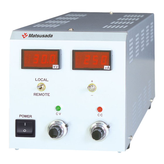
2 Exterior view diagram 2 Exterior view diagram 2-1 Front Panel ① POWER ON/OFF Switch ② select Switch LOCAL/REMOTE (Switch after it pulls it forward once.) ③ Output Volt meter ④ Output Current meter ⑤ Polarity select switch( Switch after it pulls it forward once.) ⑥... -
Page 12: 2-2 Rear Panel
2 Exterior view diagram 2-2 Rear Panel ① Heat sink ② Output connector (CN-30-MHVR) ③ Output connector (CN-30-MHVR) ④ Remote connector(36pin) ⑤ GND terminal ⑥ FUSE(3A) ⑦ AC input connector (AC100-240V)) Size : 142H×430D×143W(mm) ※ It doesn’t contain the projection... - Page 13 3 Instructions for operation 3 Instructions for operation 3-1 Operation 1. For your safety connect the ground terminal of power supply to the earth. 2. Select the output polarity by polarity change switch. Connect the output cable to selected polarity’s output connector, and then connect cable terminal to the load. 3.
- Page 14 3 Instructions for operation 7. REMOTE control (1) Same operation as LOCAL operation can be done with external voltage. (2) Instead of turning current setting dial clockwise, input 0 to +10Vdc between pin 6 and pin 24 on rear panel connector. And instead of turning voltage setting dial clockwise, input 0 to +10Vdc between pin 4 and pin 22 on rear panel connector.
-
Page 15: 3-2 Over Current Protection (O.c.p)
3 Instructions for operation 3-2 Over current protection (O.C.P) This unit has an over current protection. When over current, the output current is limited by decreasing the output voltage. 3-3 Output monitor 3-3-1 Output current monitor (L1) At the time of maximum output current, a voltage of 10V is outputted from the output current monitor terminal on the rear panel. -
Page 16: 4 Optional Functions
4 Optional Functions 4 Optional Functions List of optional functions 4 – 1 Door switch / Remote switch ON / OFF (LDS) Door switch ( ) Select the external switch to OFF, and the high voltage output is cut off. When the output is once cut off, high voltage cannot be output for extra safety even if the external switch is selected to ON.
Need help?
Do you have a question about the CZE-30PN0.25 and is the answer not in the manual?
Questions and answers