Table of Contents
Advertisement
Quick Links
Advertisement
Table of Contents

Related Manuals for Matsusada Precision DRK Series


Summary of Contents for Matsusada Precision DRK Series
- Page 1 Instruction Manual DRK series MODEL *116.9.079* B/N 116.9.079 Rev. 1.22...
- Page 2 ◆ No part of this publication may be reproduced, stored in a retrieval system, or transmitted, in any form, or by any means, mechanical, electronic, photocopying, recording, or otherwise, without the prior written permission of Matsusada Precision. ◆ No patent liability is assumed with respect to the use of the information contained herein.
-
Page 3: For Safe Use Of The Product
Bistable push button switch for preventing electric shock) Indicates the possible danger of death if Bistable push button switch you drink it and burns or blindness if it attaches. Indicates the possible danger of exposure Alternative Current to radiation. DRK series... - Page 4 ◆ Do not process or damage power cables It may result in electric shock or fire. ◆ Regarding the input voltage Check the page describing the input terminals and input voltage in the instruction manual. Do not provide any voltage out of the specifications. DRK series...
- Page 5 In order to avoid electric shock, ground the terminals to discharge using a short-circuit grounding apparatus and check the voltage again. The terminals here mean all terminals like input and output terminals and terminals for communications and remote controls. DRK series...
- Page 6 ◆ Do not store or use the product in a place where conductive foreign matter like iron powder can be collected into the air inlet and outlet. It may cause a short circuit, resulting in electric leakage, burning fire, or malfunction. DRK series...
-
Page 7: Table Of Contents
4-3-1 Overview of Protection Functions ......................14 4-3-2 Display ..............................15 4-3-3 Power Failure Protection Disabling Option - LN ................... 17 4-4 Set Up Function ............................17 4-5 Configuration Function ........................... 18 4-5-1 Operational selection function in an overload state (OCP/OPP Act.) ........... 18 DRK series... - Page 8 7-10 Remote Mode / Door (Interlock) switch (LD) ..................48 7-11 Error Display ............................49 7-11-1 Master/Slave Option ........................... 49 7-11-2 Three-Phase and Three-Phase Master/Slave Options ............... 49 7-11-3 Single-Phase Three-Wire Option ......................50 7-12 FAULT Status Output ........................... 50 7-13 Capacitive Load ............................ 50 DRK series...
- Page 9 Page 8 Digital Control Operation ........................51 8-1 External Appearance ..........................51 8-1-1 DRK series -LGb Option (Rear Panel) ....................51 8-1-2 DRK series -LGob Option (Rear Panel) ....................51 8-1-3 DRK series -LUs1 Option (Rear Panel) ....................51 8-2 Digital Connection Diagram ........................52 8-2-1 DRK series -LGb Option ........................
-
Page 11: Outline And Features
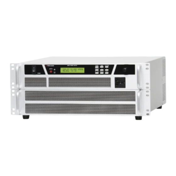
1 Outline and Features 1-1 Outline The DRK series is a programmable AC power source featuring well-regulated and high performance, and it provides high power 4kVA in a 4U 19-inch rackmount model. We have succeeded in making the conventional large and heavy AC power source units smaller/lighter/more highly efficient with the switching method. -
Page 12: Lineup
10/40 DRK 4k 40/160 20/80 DRK 2k -LMsm/-LMss* 40/160 20/80 60/240 30/120 DRK 2k -LMsm/-LMssx2* 80/320 40/160 DRK 2k -LMsm/-LMssx3* Three-phase 20/80 10/40 DRK 2k -LPhu/-LPnw Single-phase DRK 2k -L1p3wm / 20/80 10/40 Three-wire -L1p3ws *Models with option DRK series... -
Page 13: Specifications
-20℃ to +70℃ temperature 20% to 80% RH (no condensation) Storage humidity A universal outlet (Front panel), Terminal board (Rear panel) Output terminal *Effective value on display: Accuracy ±1.5% of full scale, reading ±1 dgt, frequency 50Hz or higher DRK series... -
Page 14: External Appearance
(5) Connector for I/F option (GPIB, USB, optical interface option) (6) CO-M cable terminal (Output option) (7) Sense terminal (-LSn option) (8) Output option I/F (Output option) Do not connect AC input to the output terminals. Doing so may damage the equipment. DRK series... -
Page 15: Dimensions
2 External Appearance 2-3 Dimensions Unit [mm] RA NGE D C / AC V LT FR Q P ROTE CT KEY LOCK ME MORY EN TER DRK series... -
Page 16: Unpacking And Installation
Before changing the system, make sure that all the devices making up the system are turned off. DRK series... -
Page 17: Installation
The front panel and rear panel of the power supply unit have a cooling air intake port and exhaust port respectively. Secure space for the ports as much as possible to use the unit in a place with good ventilation. DRK series... -
Page 18: Detail Of Remote Connector
Do not make short between PIN 5 and PIN10 on the user side as they are connected inside the power supply unit. Install the supplied D sub connector cover when in use. Attach the supplied Dsub-25pin male connector and the remote connector cover to TB1 to avoid touching the remote connector REMOTE(TB1). DRK series... -
Page 19: Connecting
• Recommended output lead lines (PVC, 105 ºC) Model DRK 500 DRK 1.2k DRK 1.5k DRK 2k Use sufficiently thick lead lines for wiring to loads. Thin lead lines cause problems of heat generation, insufficient voltage resistance, voltage drop, etc. DRK series... -
Page 20: Electric Load With A Lot Of Noise
In addition, when an inductor and other inductive loads are connected, connect a freewheel diode to absorb counter electromotive force which occurs on output OFF as the figure below. Diode Diode Capacitor, etc. Inductor, etc. DRK series... -
Page 21: Functions
It moves the cursor to the left direction to enter the value. 10. ▶/AC Key switch It moves the cursor to the right direction to enter the value. DISP Key switch Pressing the switch goes to the monitor screen. Pressing and holding it goes to the Config screen. DRK series... - Page 22 As “RECALL ERROR” appears, the memory recalling screen will displayed. It enables/disables the key operation. Press and hold the switch to enable/disable the keylock state. 14. Numerical value setting encoder It changes values (numeric, +, -, etc.) at the cursor position. DRK series...
-
Page 23: Output And Load
There is no DC mode when in Master/Slave mode. Maximum output voltage [V] Maximum current [A] Maximum Model power [W] 100V range 200V range 100V range 200V range DRK 500 DRK 1.2k 212.2 424.4 DRK 1.5k DRK 2k 1300 DRK series... -
Page 24: Protection Functions
4 Functions 4-3 Protection Functions 4-3-1 Overview of Protection Functions The DRK series offers the following protection functions and setting ranges. With OVP/OCP/OPP, when an abnormality is detected, output is stopped. ILimit reduces the output voltage so that the current does not exceed the set value. -
Page 25: Display
Input voltage abnormality, it means input voltage is out of decided voltage. Output is cut off and the following message is displayed. FAULT AC DOWN turn off power, and then, turn When ACF protection is effective, remove the cause of ACF, on power again. DRK series... - Page 26 *An error message to protect the equipment may appear during instantaneous suspension of power (input voltage). Turn off power and turn on power again to release the equipment from the state. DRK series...
-
Page 27: Power Failure Protection Disabling Option - Ln
Overvoltage protection (OVP) setting value Overcurrent protection (OCP) setting value Overpower protection (OPP) setting value ILimit (peak)* When turning on the POWER switch again, it starts up in the setting state just before it was turned off. DRK series... -
Page 28: Configuration Function
The configuration function provides the selection of an operation in an overload state. 4-5-1 Operational selection function in an overload state (OCP/OPP Act.) The DRK series has a function to select an operation in an overload state at the AC mode (overcurrent or overpower). -
Page 29: Operation Method
Our factory default setting is the “Local Mode.” Local Mode (Initial Setting) 5-1-1 Display Detail The display changes depending on the output status. 1. Output OFF OUTPUT OFF Lo AC 2. Output ON (Monitor) 100.0 V 20.00 A 2000 VA 50.0 Hz Lo AC DRK series... -
Page 30: Setting Output Voltage
) and configure the voltage value with the numerical value setting encoder. ◄/DC ►/AC Turn the numeric setting encoder clockwise to "+" and counterclockwise to "-". +144.4 V 6.75A 975 W (DC mode setting) VSET + 144.4 V DRK series... -
Page 31: Setting Output Frequency
RANGE 100.0 V 15.00 A 1500 VA Lo (100 V) 50.0 Hz Lo AC range setting key switch RANGE 200.0 V 7.50 A 1500 VA Hi (200 V) range setting 50.0 Hz Hi AC key switch RANGE DRK series... -
Page 32: Setting Ilimit (Peak) / Ocp / Ovp / Opp
PROTECT 100.0 V 20.00 A 2000 VA (OVP setting) OVPSET 150.00 A key switch PROTECT 100.0 V 20.00 A 2000 VA (OPP setting) OPPSET 20.00 A key switch PROTECT (*The display in the figure indicates the output status.) DRK series... - Page 33 5. On the OPP setting display, move the blinking cursor part with the left (right) direction key ) and set the OPP with the numerical value setting encoder. ◄/DC ►/AC 100.0 V 20.00 A 2000 VA OPPSET 2000 VA (*The display in the figure indicates the output status.) DRK series...
-
Page 34: Storing In/Calling Up From The Memory
Select a memory number to register on the “storing in the memory” screen with the numerical value setting encoder. MEM 1 100.0 V 20.00 A STORE 50.0 Hz Lo AC Press and hold the key switch for one second or longer to call up setting values of ENT/LOCK the selected memory number. DRK series... -
Page 35: Setting Key Lock
Set the operation in an overload state (such as overcurrent or overpower) by using the numerical value setting encoder. Turn the dial clockwise to “Cut off” and counterclockwise to “Limit.” Config OCP / OPP Act. Limit Config OCP / OPP Act. Cut off DRK series... -
Page 36: Remote Mode
Power supply Customer’s connection internal circuit TTL signal (Common) Hi : Local Lo : Remote 5 kΩ 100 Ω External relay (Common) OPEN : Local SHORT : Remote *Connect the TTL signal or external contacts as the figure above. DRK series... -
Page 37: Select Remote Mode
[2] When the output frequency setting is performed in the Remote Mode. Power supply Customer’s connection internal circuit TTL signal - (Common) Hi : Local Lo : Remote 5kΩ + 100Ω External relay (Common) OPEN : Local SHORT : Remote DRK series... -
Page 38: Remote Switch On/Off
When a fault condition occurs, after removing the cause, turning OFF clears the fault condition and the output will be enabled. Power supply Customer’s connection internal circuit TTL signal Hi : OUTPUT OFF (Common) 5 kΩ Lo : OUTPUT ON 100 Ω External relay (Common) OPEN :OUTPUT OFF SHORT :OUTPUT ON DRK series... -
Page 39: Remote Output Voltage Programming
External voltage Input impedance ≒10kΩ Control voltage - Output voltage Output voltage 424.2V 300V 300Vrms 212.1V 150V 150Vrms 3.53V 7.07V Control voltage AC mode Lo Range max. Lo (100V) range AC mode Hi Range max. Hi (200V) range DRK series... -
Page 40: Remote Output Frequency Programming
When the unit is in remote output voltage range change mode, two ranges of Lo(100V)/Hi(200V) can be changed with remote control. Power supply Customer’s connection internal circuit TTL signal - (Common) Hi : Lo(100V)range Lo : Hi(200V)range 5kΩ + 100Ω External relay (Common) :Lo(100V)range OPEN SHORT :Hi(200V)range DRK series... -
Page 41: Other Features
OFF and ON again, or turn the remote switch OFF. (It is also cleared by setting the POWER ON/OFF switch to OFF.) If the external switch is open at the output OFF, it is cleared by shorting the external switch. DRK series... -
Page 42: Fault Status Output
Use Withstand voltage 30V or less, SINK current 5mA or less. Power supply Customer’s connection internal circuit (Example) When Vcc is 24V R = 4.7kΩ Less than 20Ω PIN11 PIN6 In case PIN 6 is used for floating, it should be used at 100Vdc or less. DRK series... -
Page 43: Remote Sensing (-Lsn Option)
Remote sensing connection diagram Load Sense Connector Compatible Wire Rods and Tools Single wire: .2 - 4.0mm Applicable wires Stranded wire: 0.2 - 2.5mm Standard strip length 6.0mm Flat-blade screwdriver (Shaft diameter φ3, Brade edge width 2.6) Applicable tool for button DRK series... -
Page 44: Setting Remote Sensing (-Lsn Option)
The voltage at the load end is constantly measured and corrected to match the set value. Since the voltage correction is performed software, the correction is applied continuously until the set voltage and the voltage at the load end match. DRK series... -
Page 45: Fault In Remote Sensing (-Lsn Option)
If SEN1 or SEN2 is selected in the sensing function setting and the sensing line is connected in reverse, FAULT state will be activated and the unit will stop. FAULT REVERSE SENSE Once the protection is activated, check the sensing line connections. DRK series... -
Page 46: Output Option
ON. The [POWER ON/OFF] switch of the master machine should be turned ON at the same time as or after the slave machine. Connect the CO-M cable and output option cable, then turn the [POWER ON/OFF] switch ON. DRK series... - Page 47 O U T P U T Slave unit 2 O U T P U T Slave unit 3 O U T P U T Load In master/slave mode, the outlet terminals are not available. DC mode is not available in master/slave mode. DRK series...
-
Page 48: Three-Phase Option Connection And Setting (-Lphu, -Lphv, And -Lphw Options)
Concerning output optional cables, do nor bundle or placed close together with other power cables (input or output) since they are used to handle minute signals. Hazardous potentials are generated at the IN/OFF connectors for options. Never touch during output. DRK series... -
Page 49: Three-Phase Master/Slave Option Connection And Setting
Phase V (Single or Master) -LPhvMsm No. 2,3 No. 1,4-7 OFF Phase V (Slave) -LPhvMss No. 2-4,8 ON No. 1,5-7 OFF Phase W (Single or Master) -LPhwMsm No. 1-3 No. 4-8 Phase W (Slave) -LPhwMss No. 1,3,4,8 ON No. 2,5-7 OFF DRK series... - Page 50 O U T P U T Phase W O U T P U T Load Take Y-connection for output. Delta connection is not available. In three-phase mode, the outlet terminals are not available. DC mode cannot be used in three-phase mode. DRK series...
- Page 51 Load Take Y connection for output. Delta connection is not available. (The output terminals -N terminals of DRK series must be connected to all the N terminals.) As for three-phase three-wire loads, use Y connection and connect each L-side terminal to the loads.
- Page 52 -LPhwMss Load Take Y connection for output. Delta connection is not available. (The output terminals -N terminals of DRK series must be connected to all the N terminals.) In three-phase mode, the outlet terminals are not available. DC mode cannot be used in three-phase mode.
- Page 53 Load Take Y connection for output. Delta connection is not available. (The output terminals -N terminals of DRK series must be connected to all the N terminals.) As for three-phase three-wire loads, use Y connection and connect each L-side terminal to the loads.
-
Page 54: Three-Phase Option Controlling
(Single-phase option displays the phase voltage.) Phase U shows the total power. Phase V and W show the individual powers. Phase U L terminal Vu-v Line voltage Phase voltage N terminal L terminal L terminal Phase W Phase V DRK series... -
Page 55: Single-Phase Three-Wire Option Connection And Setting
(input or output) since they are used to handle minute signals. Hazardous potentials are generated at the IN/OFF connectors for options. Never touch during output. (This is the same potential as the N potential of the output.) DRK series... -
Page 56: Single-Phase Three-Wire Option Controlling
Output voltage setting: Set by line voltage. (Phase voltage / Half of the output voltage) Range setting : Press and hold to change the range. DC/AC setting : Disabled When switching between single-phase three-wire and stand-alone use, the setting values become the default value. DRK series... -
Page 57: Single-Phase Three-Wire Option Display
The power of Phase L1 (-L1p3wm) shows the sum of the power of Phase L1 (-L1p3wm) and Phase L2 (- L1p3ws). Phase L2 (-L1p3ws) shows its phase power. (-L1p3wm) L terminals Phase voltage N terminals Line voltage Output voltage (Line voltage) Lo: 0 to 300.0V Phase voltage Hi: 0 to 600.0V L terminals (-L1p3ws) DRK series... -
Page 58: Ilimit (Peak)/Ocp/Ovp/Opp Setting
7-10 Remote Mode / Door (Interlock) switch (LD) Master/Slave Option The function is available in Master (-LMsm option). Three Phase Option The function is available in Phase U (-Phu). Single-Phase Three-Wire Option The function is available in Phase L1 (-L1p3wm). DRK series... -
Page 59: Error Display
-LPhu, -LPhv, -LPhw Option See [7-2 Three-Phase Option Connection and Setting]. -LPhuMsm, -LPhuMss / -LPhvMsm, -LPhvMss / -LPhwMsm, -LPhwMss See [7-3 Three-Phase Master/Slave Option Connection and Setting]. DRK series... -
Page 60: Single-Phase Three-Wire Option
Each model is limited to one third of the capacitance value of the capacitor load that consumes the maximum power. Meanwhile, the capacitor which is installed on the line voltage in three-phase has three times the capacitance of each phase. Note that the capacity value should be set within the limitation. DRK series... -
Page 61: Digital Control Operation
8 Digital Control Operation 8 Digital Control Operation 8-1 External Appearance 8-1-1 DRK series -LGb Option (Rear Panel) IEEE-488 ADDRESS (1) IEEE-488 connector (2) ADDRESS setting switch 8-1-2 DRK series -LGob Option (Rear Panel) UNIT (1) Optical fiber cable connector... -
Page 62: Digital Connection Diagram
8 Digital Control Operation 8-2 Digital Connection Diagram 8-2-1 DRK series -LGb Option GPIB controller GPIB cable DRK series -LGb Option (Rear Panel) IEEE-488 ADDRESS For details on the address setting switches, see [8-3-2 GPIB and Delimiter Settings]. DRK series... -
Page 63: Co-G32, Drk Series -Lgob Option
8 Digital Control Operation 8-2-2 CO-G32, DRK Series -LGob Option CO-G32 Rear panel GPIB cable GPIB controller Optical fiber cable DRK series -LGob Option (Rear Panel) UNIT Set the connected device setting switch (Switch 8) to OFF. Doe details on the UNIT number setting switch, see [8-3-3 UNIT Number and Connected Device Setting]. -
Page 64: Co-Opt2-25/Gp-Opt2-9/Gp-Opt4-25, Drk Series -Lgob Option
8 Digital Control Operation 8-2-3 CO-OPT2-25/GP-OPT2-9/GP-OPT4-25, DRK Series -LGob Option CO-OPT2-25 CO-OPT2-9 CO-OPT4-25 Optical fiber cable AC Adapter DRK series -LGob Option (Rear Panel) UNIT Set the connected device setting switch (Switch 8) to OFF. Doe details on the UNIT number setting switch, see [8-3-3 UNIT Number and Connected Device Setting]. -
Page 65: Usb-Opt, Drk Series -Lgob Option
8 Digital Control Operation 8-2-4 USB-OPT, DRK Series -LGob Option USB cable USB controller Optical fiber cable DRK series -LGob Option (Rear Panel) UNIT Set the connected device setting switch (Switch 8) to OFF. Doe details on the UNIT number setting switch, see [8-3-3 UNIT Number and Connected Device Setting]. -
Page 66: Co-E-32, Drk Series -Lgob Option
8 Digital Control Operation 8-2-5 CO-E-32, DRK Series -LGob Option LAN cable CO-E32 Rear panel LAN controller Optical fiber cable DRK series -LGob Option (Rear Panel) UNIT Set the connected device setting switch (Switch 8) to OFF. Doe details on the UNIT number setting switch, see [8-3-3 UNIT Number and Connected Device Setting]. -
Page 67: Drk Series -Lus1 Option
8 Digital Control Operation 8-2-6 DRK Series -LUs1 Option USB controller USB cable DRK series -LUs1 Option (Rear Panel) DRK series... -
Page 68: Functions Overview
Set the GPIB address using the "Address setting switch" on the rear panel of -LGb option in CO-G32 / DRK series. Use Switch 1 (LSB) through Switch 5 (MSB) to set in binary. Each switch shows logic 1 by when set to ON (left or up). -
Page 69: Setting Unit Number And Connected Device
USB-OPT CO-E32 Matsusada power supplies with -LGob option Connected device UNIT number Not used DRK series -LGob option [Setting example] UNIT number: Connected device: CO-G32 [Factory setting] UNIT number: 1, Connected device: OFF Prior to this setting, be sure to turn off the power because the setting is read when the input power is turned on. -
Page 70: Setting Co-Opt2-25/Co-Opt2-9
(Data input) (Data output) (GND) (Data input) D-Sub 25-pin FEMALE D-Sub 9-pin MALE Communication parameter Baud rate asynchronous 9600 [bps] (fixed) Data length 8 [bit] Stop bit 1 [bit] Parity None Flow control None Delimiter is CR(0D ) fixed. DRK series... -
Page 71: Usb Configuration
Delimiter is CR(0D ) fixed. 8-3-6 USB Configuration When the -LUs1 option is installed on the DRK series, please download and install the USB driver from our website. To install the USB driver, refer to the downloaded "USB Driver Installation Guide". -
Page 72: Digital Program
Sets the output voltage of all the units to 300V. (2) #AL OUT ON: Turns the output of all the units to ON. (Remark)The following commands support multiple commands. VCN, IPKSET, OCP, OVP, OPP, FRQ, OUT, VRNG, DC, AC, DCPOL, OCOPACT, REN, DRK series... -
Page 73: Ren And Gtl Commands
If a command with no response is sent, nothing will be returned. Example of “STS” Command received: “STS=OFF LO 100 AC” H H H H H H H H H H H H H H H H H H DRK series... -
Page 74: Checking Digital Operation
8 Digital Control Operation 8-5 Checking Digital Operation 8-5-1 DRK series -LGb Option DRK series is controlled via GPIB. Voltage is actually output. Do not connect any load to the product until the operation checking has been completed. -
Page 75: Co-G32 And Drk Series -Lgob Option
(4) Connect DRK series and CO-G32 Using the supplied Optical fiber cable, connect “Optical fiber cable connector (OUT)” in CO-G32 and “Optical fiber cable connector (IN)” in DRK series. When not in use, be sure to install a cap on the Optical fiber cable connector. -
Page 76: Co-Opt2-25/Co-Opt2-9/Co-Opt4-25 And Drk Series -Lgob Option
(3) Connect CO-OPT2-25/CO-OPT2-9/CO-OPT4-25 to DRK series. Using the supplied Optical fiber cable, connect CO-OPT2-25/CO-OPT2-9/CO-OPT4-25 and “Optical fiber cable connector (IN)” in DRK series. When not in use, be sure to install a cap on the Optical fiber cable connector. (4) Turn on the power of DRK series. -
Page 77: Usb-Opt And Drk Series -Lgob Option
Do not connect any load to the product until the operation checking has been completed. (1) Set UNIT number and connected device. Set the UNIT number to “1” with UNIT number setting switch on the rear panel of DRK series, and set “USB-OPT” as the connected device. -
Page 78: Co-E32 And Drk Series -Lgob Option
(4) Connect DRK series and CO-E32 Using the supplied Optical fiber cable, connect “Optical fiber cable connector (OUT)” in CO-E32 and “Optical fiber cable connector (IN)” in DRK series. When not in use, be sure to install a cap on the Optical fiber cable connector. -
Page 79: Drk Series -Lus1 Option
Do not connect any load to the product until the operation checking has been completed. (1) Connect to USB. Connect a commercially available USB cable to DRK series and connect it to a USB controller (computer, etc.). (2) Turn on the power of DRK series. -
Page 80: Command
Read the action setting at overload in AC mode. *1 The range of values that can be set depends on the operation mode. *2 Disabled in Master/Slave mode, Three-phase mode, or Single-phase three-wire mode. *3 Disabled in AMP mode. DRK series... -
Page 81: Description Of Command
Refer to Syntax e.g.(4). Numerical values should be written with a maximum of 6 characters, including the decimal point. If it exceeds 6 characters, it will be ignored as an invalid command. Refer to Syntax e.g.(5). This command supports multiple commands. DRK series... - Page 82 Refer to Syntax e.g.(4). Numerical values should be written with a maximum of 6 characters, including the decimal point. If it exceeds 6 characters, it will be ignored as an invalid command. Refer to Syntax e.g.(5). This command supports multiple commands. DRK series...
- Page 83 Refer to Syntax e.g.(4). Numerical values should be written with a maximum of 6 characters, including the decimal point. If it exceeds 6 characters, it will be ignored as an invalid command. Refer to Syntax e.g.(5). This command supports multiple commands. DRK series...
- Page 84 This command programs the action setting at overload (overcurrent or overpower) in AC mode. (Syntax e.g.) (1) OCOPACT LIM: Current limit by overload (2) OCOPACT OFF: Output cutoff by overload (Description) Changing the action by overload (overcurrent or overpower) during output will turn off the output. This command supports multiple commands. DRK series...
- Page 85 This command returns the monitor value of the output current from 0.00 to the rated current. (In -LMsm option Master/Slave mode, it is the sum of the maximum values for each series connected). (Syntax e.g.) IM? (Return) (1) Im = 20.0: Monitor value = 20.00A (2) IM = 1.20: Monitor value = 1.20A DRK series...
- Page 86 (6) STS = OFF LO 100 AC CONF: Output cut off in Local control 100V range AC mode and Configuration Error state (7) STS = OFF LO 100 AC COMM Output cut off in Local control 100V range SC mode and Communication Error state DRK series...
- Page 87 (In -LMsm option Master/Slave mode as well as -L1p3wm option single-phase three-wire mode, it is the sum of the maximum values for each series connected). (Syntax) OPP? (Return e.g.) (1) OPP = 1100: Overpower protection is set to 1100VA. (2) OPP =12: Overpower protection is set to 12VA. DRK series...
- Page 88 This command returns the action setting at overload (overcurrent or overpower) in AC mode. (Syntax) OCOPACT? (Return e.g.) (1) OCOPACT = LIM: Current limit by overload is set. (2) OCOPACT = OFF: Output cutoff by overload is set. DRK series...
- Page 89 Revision History Rev. No. Rev. Date Revision Contents 2021/05 First edition 2021/07 Corrected some descriptions. Removed the description of -LUs1 option accessories. 1.22 2022/04...
Need help?
Do you have a question about the DRK Series and is the answer not in the manual?
Questions and answers