Table of Contents
Advertisement
Quick Links
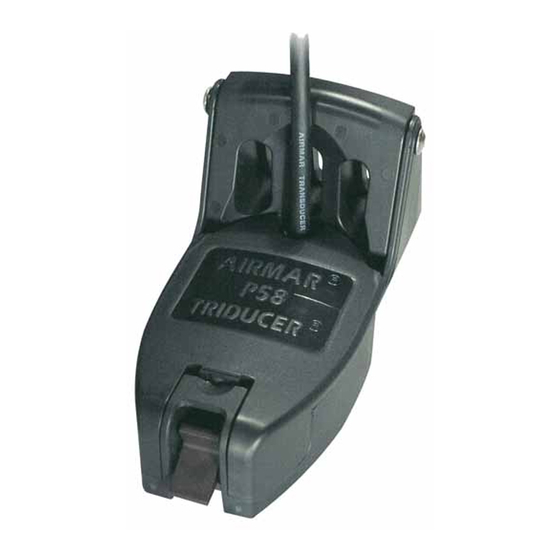
OWNER' S GUIDE
Transom-Mount, TRIDUCER
U. S. Patents: 5,606,253; 5,719,824
IMPORTANT: Please read the instructions completely
before proceeding with the installation. These
instructions supersede any other instructions in your
instrument manual if they differ.
WARNING: Always wear safety goggles and a dust
mask when installing to prevent personal injury.
CAUTION: Never use solvents. Cleaners, fuel, paint,
sealants, and other products may contain strong
solvents, such as acetone, which attack many plastics
greatly reducing their strength.
Applications
• Vertically orients sound beam on hull with deadrise angle up to 22°
• Accommodates transom angles from 2
• Requires 89mm (3-1/2") of headroom to install
• Not recommended for boats with large inboard engine(s)
• Not recommended for stepped transoms, as multisensor will be
difficult to adjust
• Good operation up to 44kn (50MPH)
• Bracket protects multisensor from frontal impact only
Tools & Materials
Screwdrivers
Pencil
Safety goggles
Dust mask
Electric drill
Drill bits:
Bracket holes
Transom hole (optional) 18mm, 11/16", or 3/4"
Cable clamp holes
Masking tape
Angle finder (some installations)
Marine sealant (suitable for below waterline)
Straight edge
Grommets (some installations)
Cable ties
Water-based anti-fouling paint (mandatory in salt water)
Figure 1. Headroom required on a stepped transom
Copyright © 2004 Airmar Technology Corp.
Multisensor
®
with Integral Release Bracket
Model P58
°
°
–22
4mm, #23, or 9/64"
21mm or 13/16"
(Furuno only)
24 mm or 15/16" or 1"
(Raymarine only)
3mm or 1/8"
minimum
headroom
89mm (3-1/2")
&
Installation INSTRUCTIONS
Record the information found on the cable tag for future reference
Part No._________________ Date___________ Frequency__________
Pretest Speed & Temperature Functions
Connect the multisensor to the instrument and spin the
paddlewheel. Check for a speed reading and the approximate air
temperature. If there is no reading or it is inaccurate, return the
product to your place of purchase.
Mounting Location
CAUTION: Do not mount in an area of turbulence or bubbles:
Near water intake or discharge openings
Behind strakes, struts, fittings, or hull irregularities
CAUTION: Avoid mounting the multisensor where the boat may
be supported during trailering, launching, hauling, or storage.
• For the best performance, the multisensor's face must be
submerged in smooth water. To identify an area of clean water,
observe the water flow off the transom while the boat is
underway.
• Allow headroom space above the bracket for it to release and
rotate the multisensor upward (see Figure 1).
• Mount the multisensor as close to the centerline (keel) of the
boat as possible. On slower heavier displacement hulls,
positioning it farther from the centerline is acceptable.
• Single drive boat—Mount at least 75mm (3") beyond the
swing radius of the propeller (see Figure 2). The starboard side
where the propeller blades are moving downward is preferred.
• Twin drive boat—Mount the multisensor between the drives.
Figure 2. Mounting location on single drive boat
NOTE: Starboard
side of hull where
propeller blades are
moving downward is
preferred.
75 mm (3")
minimum beyond
swing radius
Copyright © 2004 Airmar Technology Corp.
Advertisement
Table of Contents

Subscribe to Our Youtube Channel
Related Manuals for Airmar TRIDUCER P58


Summary of Contents for Airmar TRIDUCER P58
- Page 1 75 mm (3") headroom 89mm (3-1/2") minimum beyond swing radius Figure 2. Mounting location on single drive boat Figure 1. Headroom required on a stepped transom Copyright © 2004 Airmar Technology Corp. Copyright © 2004 Airmar Technology Corp.
- Page 2 (2) CAUTION: Do not position the multisensor Figure 3. Assembling deeper in the water than necessary to avoid Copyright © 2004 Airmar Technology Corp. increasing drag, spray, and water noise and reducing boat speed. Installation 1. Apply marine sealant to the threads of two, #10 x 1-1/4", self- WARNING: Always wear safety goggles and a dust mask.
- Page 3 CAUTION: Do not remove the connector to ease cable routing. If the cable must be cut and spliced, use Airmar’s splash-proof Junction Box No. 33-035 and follow the instructions provided. Removing the waterproof connector or cutting the cable, except when using a water-tight junction box, will void the sensor warranty.
- Page 4 Insert the forward tabs of the cover into the housing. Press Copyright © 2004 Airmar Technology Corp. AIRMAR ® 35 Meadowbrook Drive, Milford, New Hampshire 03055-4613, USA ■ TECHNOLOGY CORPORATION www.airmar.com Copyright © 2004, 2009 Airmar Technology Corp. All rights reserved.
Need help?
Do you have a question about the TRIDUCER P58 and is the answer not in the manual?
Questions and answers