
Subscribe to Our Youtube Channel
Related Manuals for Toa EX-610


Summary of Contents for Toa EX-610
- Page 1 EXES-6000 EX-610/620/630 INTERCOM SYSTEM Fully Electronic Exchange EX-610/620/630 INSTALLATION HAND BOOK...
- Page 2 WARNING: (For U.S.A. only) This equipment generates, uses, and can radiate radio frequency energy and if not installed and used in accordance with the instructions manual, may cause interference to radio communications. It has been tested and found to comply with the limits for a Class A computing device pur- suant to Subpart J of Part 15 of FCC Rules, which are designed to provide reasonable protection such interference when operated in a commercial environment.
-
Page 3: Table Of Contents
2. Example of Exchange Mounted on Intercom Cabinet Rack 3. Recommendable Example of Exchange Mounted on Amplifier Cabinet Rack 4. Specifications Related to Installation 5. Functions of Units Mounted on Exchanges EX-610/620/630 (Central Processing Unit) OC (Output Control Unit) . -
Page 4: Introduction To The Installation Manual For Exes-6000
Selection of functions which satisfy your needs and setting up these functions in the respective equipment. This "Installation Handbook of Exchanges EX-610/620/630 for EXES-6000 System" contains technical instructions as to connection of exchange, etc, mentioned in the above Paragraph (1). In addition to this, the proper installation of the system necessitates the other installation manuals dealing with the selection of the function and its programming referred to in the above Paragraph (2). -
Page 5: Part1. Outlines Of Exes-6000 System And Related Equipment
One terminal board BX-610 or BX-620 can connect a maximum of 64 stations (EX-610) or 128 stations (EX-620) to the exchange all-call plus 15 paging zones and 8 tie-line links. The exchange and the terminal board are connected by junction cable YR-810 (2-wire) for stations and YR-801 (4-wire) for paging and tie-line links. -
Page 6: Example Of Exchange Mounted On Intercom Cabinet Rack
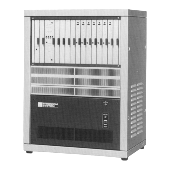
400mm) is not available.) Note.* The Exchange Cabinet Rack CR-610 or CR-620 includes Perforated Panels PF-013A and PF-023A. Exchange EX-610 (for 64 stations) Power Supply Unit DS-620 Power Switch AC Fuse 3A(110V/120V), 1.5A(220V/240V) DC Fuse 20A(for use of 65 ~ 128 stations) - Page 7 Exchange EX-630 (for 256 stations) Central Processing Unit CP-66. Output Control Unit OC-62 Highway Control Unit HC-64 Signal Generating and Distributing Unit SG-62 Conference Link Unit CL-62A (In this location, DL-62A is also mountable.) Duplex Link Unit DL-62A (CL-62A may be inserted into these positions instead of DL-62A.)
-
Page 8: Recommendable Example Of Exchange Mounted On Amplifier Cabinet Rack
EX-630: 109kg (240.30 Ibs.) without battery Caution. Both top and side panels are perforated for ventiation (EX-610/620). Do not place things on the top panel or close to the side panels. (Intercom cabinet rack) For maintenance works, allow much space between the wall and the cabinet rack. -
Page 9: Functions Of Units Mounted On Exchanges Ex-610/620/630
5. Functions of Units Mounted on Exchanges EX-610/EX-620/EX-630 5-1 CP (Central Processing Unit) Function: Reads out the exchange procedures written into the memory (ROM) and collates the data from stations for traffic processing. 5-2 OC (Output Control Unit) Function: Stores temporarily the output data from the CP unit and distributes them to each unit. -
Page 10: Sg (Signal Generating & Distributing Unit)
(Example for HC-64) LINE ADDRESS Calling Station (T): No. 413 (200+ 128 + 64+ 16 + 4 + 1 = 413) Called Station (R): paging No. 25 (16 + 8 + 1 = 25) 5-4 SG (Signal Generating and Distributing Unit) Function: Composed of 8 kinds of signal generators (calling, privacy/disconnected, busy, dialing, zone paging, all call, priority/executive priority, registration confirmation/call holding/mic-off) and distributors. -
Page 11: Dl (Duplex Link Unit)
One DL unit is provided with 4 links. Up to 3 DL units can be mounted in the EX-610 and up to 4 in the EX-620/630. 5-6 CL (Conference Link Unit) -
Page 12: Part2. Installation Of Exes-6000 System
PART2. INSTALLATION OF EXES-6000 SYSTEM 6. Installation of the EXES-6000 System 6-1 Exchanges Pay particular attention to the following points during installation of the exchange: The layout should allow easy servicing and inspection. The exchange is compact and lightweight; however it is impor- tant to ascertain the strength of the floor or wall on which it will be placed. -
Page 13: Cable Installation
As a rule, private branch cables are to be used for wiring between indoor terminal boards, intermediate terminal boards, main terminal boards, etc. Exchanges (EX-610/620) Terminal Boards (BX-610/620) YR-810 YR-801 Amplifier (s) for Paging 1. -
Page 14: Wiring
7-3 Wiring 1. General Information Wiring should be done independently of public telephone lines. Otherwise the EXES-6000's line (+30 dBm) can cause cross-talk in the telephone line. Wiring conduit is often installed underground or embedded in building structures such as walls and floors, so care must be taken to draw up a wiring plan that has ample reserve for future exten- sion of the system and that can be adapted to future remodelling or expansion of the building it is housed in. -
Page 15: Connection Of Equipments
8. Connection of Equipments 8-1 Connection of Power Supply 1. DS-610 (for EX-610) The connection on the terminals of the power section is illustrated below. When batteries are to be connected, connect the connector after plugging into the AC power source. Connect to the AC power source, as illustrated below, after setting the system. - Page 16 2. DS-620 (for EX-620) The following procedures should be followed for connection of the power supply unit. (Refer to illustrations.) 1. Turn off a power switch on the front panel. 2. Connect cables coming from the rear frame of the exchange to the terminal board of the power supply unit, confirming the colour of cables and the voltage specification marked on the cables.
- Page 17 3. DS-630 (for EX-630) Use following steps for connection of the power supply unit referring to illustrations. 1. Turn off a power switch on the front panel. 2. Connect cables coming from the mother boards on the rear frame of the exchange to the terminal boards of the power supply unit, confirming the colours of cables and voltage markings on the cables.
- Page 18 7. Turn on the battery power switch of the battery case, and the battery circuit is activated. 8. Confirm the colour of power indication lamp. AC operation: Green Battery operation: Red 9. Conduct a battery operation test about 60 hours after power is switched on since sufficient time is necessary for the batteries to charge fully.
-
Page 19: Connection Between The Exchange And The Terminal Board (Bx-610 Or Bx-620)
EXES-6000 system. Use the YR-810 cable (2-wire and for 8 stations) or the YR-801 cable (4-wire and for 8 paging zones and 8 links of 1. Wiring Example when Exchange EX-610 is used 1. For LM units: Connect J1 through J8 of the exchange to L1 through L8 of the terminal board with the YR- 810 cable. - Page 20 3. Wiring Example when EX-630 is used 1. For LM units: Connect K1 through K16 of the exchange to L1 through L16 of the terminal board (A), and L1 through L16 of the exchange to L1 through L16 of the terminal board (B). Use YR-810 cable for this connection.
-
Page 21: Connection Of The Terminal Board (Bx-610 Or Bx-620) To The Main Terminal Board
8-3 Connection of the Terminal Board (BX-610 or BX-620) to the Main Terminal Board Route cables from the main terminal board to the terminal board (BX-610 or BX-620) and connect them to the individual clip terminals using clipping tool YC-105 (Optional accessory). See Fig. -
Page 22: Connection Of The Station Plug To The Exchange Jack
Fig. 4 Terminal Board BX-620 Appearances 8-4 Connection of the Station Plug to the Exchange Jack Clip Teminal of Teminal Boards (BX-610/620) To Exchange Junction Cable YR-801, 810 Optional Accessary Knock-out Station 2-Pin Plug YC-602 Cover 2-Pin Jack YC-601 To other station Note: 1.Use 4"... -
Page 23: Connection Of Stations
8-5 Connection of the station For station installation, refer to the instruction manual of the station. When installing the desk-top/wall-mounted station, use the YC-601 or YC-603 station jack for connection. The maximum dis- tance between the station and the station jack is 3 meters since the station cable is 3 meters in length. -
Page 24: Connection And Adjustment Of Equipment
9. Connection and Adjustment of Equipment 9-1 Connection of the Speaker Station (Simplified Paging) In the EXES-6000, instead of using a station, a speaker for one-way conversation can be installed using a jumper in the LM-62B. This is possible at each station position on the LM-62B. 1. -
Page 25: Paging Connection
Solder the electrolytic capacitor (33 µ F ) to the terminals, and "PO" and "No. 319" (paired with No. 312) for EX-620, "PO" and "No. 255" (paired with No. 248) for EX-610 of "Station Paging Assignment" on the rear of exchange frame. Do not connect No. -
Page 26: Station Paging (For Ex-610/620)
3. Cut off unnecessary jumper wires (JP3 ~ JP8) and resistor (R126 ~ R826) of the LM unit according to the zone allocation. 4. If the exchange is the EX-610, both No. 256 and No. 263 pins of the assignment plug must not be connected to the GND pin. - Page 27 JP801, JP105 ~ JP805) of the LM unit according to the zone allocation. 4. If the exchange is the EX-610, both No. 256 and No. 263 pins of the assignment plug must not be connected to the GND pin. Fig. 5 LM-62B/65 units Fig.
- Page 28 To another LM unit Fig.7 Station Paging Assignment Plug Table 3 Wiring of Station Paging Assignment Plug Table 4 Station Paging Connection (LM Unit) Note: Mark the disconnected jumper wire or resistor with "X". Fig. 8 LM-62C/65C units Fig. 9 PI unit -25- Bottom Bottom...
- Page 29 LM unit having been connected to a connector 46A of each LM unit. EX-610: LM1 - LM7 (Station No.200 ~ No.255) EX-620: LM1 ~ LM15 (Station No.200 ~ No.319) 6. Use solder to connect each PI output pin (PO through P7) of the plug to the input pin of the first or last station number of the corresponding paging zone.
-
Page 30: Station Paging (For Ex-630)
2.2 Station Paging (for EX-630) (1)The paging outputs of the PI units must be connected to the assigned lines of the LM unit via the SA unit. Follow the pro- cedures below to make the required connections. 1. After determining of the zone allocation, record it in the Sta- tion Paging Table of "Initial Checking Sheet for the System (CP-64/66)". - Page 31 Table 2 Station Paging Connection (LM-62A Unit) Paging distribution line LM No. Station Note: Mark the disconnected jumper wire or resistor with "X". Table 3 Station Paging Connection (LM-62B/62C/65/65C Units) Paging distribution line LM No. Station Note: Mark the disconnected jumper wire or resistor with "X". Unrequired paging line Unrequired paging line Fig.
-
Page 32: Calling Tone Modifications
1. Be sure to use the PI-62 Type 2, a modified version of Type 1. 2. Insert the Type 2 into the PI2 slot (Zone No.8 ~ No.15) when the EX-610 or EX-620 exchange is used, and into the PI4 slot (Zone No.24 ~ No.31) when the EX-630 exchange is used. -
Page 33: Bgm Equipment Connection
(JP103-JP803) decreases the volume by 6 2. Cutting off the both of the paired jumper wires (JP103- JP803, JP102-JP802) decreases the volume by 12 dB. Exchange without rear panel EX-610/620/630 YR-810/801 Station No. 0 Station No.4 BGM player No.4 BGM player No.5... -
Page 34: Check When Power Is Switched On
Connect batteries after confirming that the system operates on AC mains. Use 2 batteries for the EX-610 and 3 batteries for the EX-620/ 630: voltage; 24V, capacity; 3.5 Ah per battery for EX-610/620, 6A per battery for EX-630. -
Page 35: System Check Flow Chart
10-3 System Check Flow Chart START DIP switch on CP correctly set ? Mini-jumper for battery back-up (JP1) ON ? Program switch on CP OFF ? Set power switch to on. Proper voltages at each output power terminal ? (Table 1) CLOCK lamp on HC lights blight ? Other lamps on HC OFF ? -
Page 36: Simple Troubleshooting
10-4 Simple troubleshooting Delimitative point for system check A system is checked for the following delimited portions. Exchange Line Station BX-610/620 YC-601/603 Exchange check An exchange is checked for the following delimited portions. (1) Speech path section SG-62, DL-62A, LM-62B, PI-62, CL-62A, TI-62,andSA-64 (2) Speech path control section CP-66, OC-62, HC-62, and HC-64 (3) Power supply section DS-610, DS-620 and DS-630... - Page 37 Printed in USA 4-92 133-21-117-1B-ABC...
Need help?
Do you have a question about the EX-610 and is the answer not in the manual?
Questions and answers