
Related Manuals for barbas BOX30 75


Summary of Contents for barbas BOX30 75
- Page 1 Installation and maintenance manual This product is not suitable for primary heating purposes Serial number: Production date:...
- Page 2 Barbas Bellfires BV.This document could contain technical inaccuracies or typographical errors. Barbas Bellfires BV reserves the right to revise this document from time to time in thecontents thereof.
-
Page 3: Table Of Contents
Contents Contents Declaration of Performance..............5 75............................. 5 75 with wood log storage module..................6 About this document................7 How to work with this document....................7 Warnings and cautions used in this document................7 Related documentation........................ 7 Description....................8 Overview of the front of the appliance..................8 Overview of the bottom of the appliance..................9 Overview of the rear of the appliance .................. - Page 4 Contents Installation of the BOX 75 with stone base......... 23 Installation of the BOX 75 with wood log storage module............23 8.1.1 Install the appliance ....................... 23 8.1.2 Connect the optional external air supply................. 24 8.1.3 Connect the flue gas pipe....................25 8.1.4 Final check on the appliance...................25 Maintenance..................
-
Page 5: Declaration Of Performance
Name, registered trade name or registered trade Barbas Bellfires BV; Hallenstraat 17; 5531 AB Bladel; The Netherlands mark and contact address of the manufacturer as required pursuant to Article 11(5) -
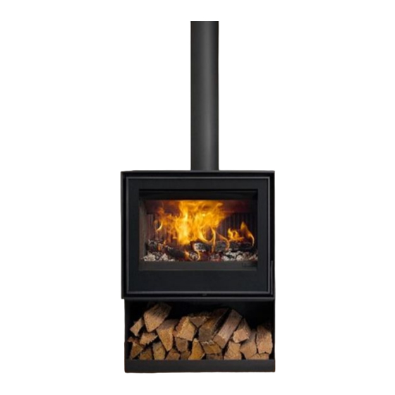
Page 6: Box 75 With Wood Log Storage Module
Name, registered trade name or registered trade mark Barbas Bellfires BV; Hallenstraat 17; 5531 AB Bladel; The Netherlands and contact address of the manufacturer as required pursuant to Article 11(5) -
Page 7: About This Document
About this document About this document This document shows the necessary information to do these tasks on the BOX • Installation • Maintenance This document refers to the BOX 75 as 'the appliance'. This document is an essential part of your appliance. Read it carefully before you do work on the appliance. Keep it in a safe place. -
Page 8: Description
Description Description Note: The appliance is a room-sealed appliance only if combustion air comes from the outer side of the building through a pipe that is connected to the combustion air inlet of the appliance. In all other cases the appliance is not a room-sealed appliance and the data for leak tightness as given in section are not valid. -
Page 9: Overview Of The Bottom Of The Appliance
Description Overview of the bottom of the appliance Airwash inlet Upper baffle Heat shield Connection for external combustion Lower baffle with secondary air inlet air supply openings BOX 30 75... -
Page 10: Overview Of The Rear Of The Appliance
Description Overview of the rear of the appliance Connection for external combustion air supply BOX 30 75... -
Page 11: Overview Of The Bottom Of The Appliance With Wood Log Storage Module
Description Overview of the bottom of the appliance with wood log storage module Connection for external combustion air supply BOX 30 75... -
Page 12: Overview Of The Rear Of The Appliance With Wood Log Storage Module
Appliance options Option Description A stone base under the appliance as alternative for the steel base. Barbas does not supply the stone base, but Stone base the installer can order a stone base according the specifi- 11.3 cations in section at a local supplier. - Page 13 Description The appliance is intended for intermittent use and is not intended for continuous use. The appliance is intended to heat the room by direct heating. It is not allowed to connect the appliance to a central-heating installation. BOX 30 75...
-
Page 14: Safety
Safety Safety Safety instructions for installation Warning: • Installation must be done by a qualified installer. • Install the appliance in accordance with the following installation instructions and the national and local applicable regulations. • Make sure that the area around the fireplace is free of flammable material at all times. -
Page 15: Clearances
Clearances Clearances Warning: • Obey the instructions in this section. Failure to follow these instruction can create a fire hazard. • Do not put the appliance directly against a flammable or non-flammable wall. Caution: Make sure that flammable materials near the appliance can never reach a temperature above 85 degrees centigrade •... - Page 16 Clearances Minimum distance to Minimum distance to Label flammable materials in Remark non-flammable mate- rials in cm See remark. Install a non-flammable hearth with a thickness of minimum 5 cm (floor stone) when the appliance is put on a flammable floor.The width (E) of the hearth must be minimum 15 cm from each side of the appliance.
-
Page 17: Safety Distances Box 30 75 With Wood Log Storage Module
Clearances Safety distances BOX 75 with wood log storage module 75 with wood log storage module Minimum dis- Minimum dis- tance to flamma- tance to nonflam- Label Remark ble materials in mable materials in cm Install a non-flammable hearth (floor stone) when the appliance is put on a flammable floor. -
Page 18: Installation Requirements
Installation requirements Installation requirements Requirements on the installation of the appliance • Make sure that the location agrees with the safety requirements. Refer to section • Make sure the floor is made of concrete or a solid pedestal of non-combustible material. - Page 19 Installation requirements • Do not use horizontal flue pipes. • The chimney outlet must be minimum 6 meter above the top of the appliance. • The chimney outlet must be minimum 40 cm above the top of a sloped roof. •...
-
Page 20: Installation Of The Box30 75 With Steel Base
Installation of the BOX30 75 with steel base Installation of the BOX 75 with steel base Install the appliance Put the appliance in the designated position. To put the appliance on a natural stone platform, refer to section Obey the safety distances. Refer to section If necessary, put a nonflammable hearth under the appliance. -
Page 21: Bottom Connection
Installation of the BOX30 75 with steel base Remove the round break out plate with a hammer. Put the collar adaptor in the open external air inlet opening. Bend out the 3 lips on the collar adaptor to attach the collar adaptor on the inlet opening. -
Page 22: Connect The Flue Gas Pipe
Installation of the BOX30 75 with steel base Connect the flue gas pipe Caution: During operation of the appliance the outer side of the flue system becomes hot. Refer to section for minimum distances to flammable material. Note: If the appliance is installed on an unlined, masonry flue with a large diameter, consider using a flue lining system to improve the performance of the appliance. -
Page 23: Installation Of The Box30 75 With Stone Base
Installation of the BOX30 75 with stone base Installation of the BOX 75 with stone base Put the stone base on the intended location of the appliance. Obey the safety distances. Refer to section Put the appliance on the stone base. -
Page 24: Connect The Optional External Air Supply
Installation of the BOX30 75 with stone base 8.1.2 Connect the optional external air supply • The appliance has the possibility to connect a supply pipe for external combustion air. During operation the appliance gets combustion air from this air duct. -
Page 25: Connect The Flue Gas Pipe
Installation of the BOX30 75 with stone base Bottom connection Remove the round break out plate at the bottom of the appliance with a hammer. If necessary, put the collar adaptor in the open external air inlet opening. Bend out the 3 lips on the collar adaptor to attach the collar adaptor on the inlet opening. -
Page 26: Maintenance
Clean the inside of the appliance with a soft brush. Clean the metal parts on the outside of the appliance with a dry lint free cloth. Use Barbas heat resistant paint spray to repair lacquer damage. Combustion air supply Make sure that the inlet of the pipe of the external combustion air supply is not blocked by leaves or other debris. -
Page 27: Remove The Heat Shield
Maintenance 9.4.1 Remove the heat shield. Refer to section 9.4.2 Remove the lower baffle. Refer to section 9.4.3 Remove the upper baffle. Refer to section 9.4.4 Remove the grate. Refer to section 9.4.5 Remove the cast iron rear panels. Refer to section 9.4.6 Remove the steel bottom plates. -
Page 28: Remove The Upper Baffle
Maintenance Push up the right side of the lower baffle a small distance (1). Lower the left side of the lower baffle a small distance (2) and remove the baffle from the appliance (3). 9.4.3 Remove the upper baffle 9.4.2 Only do this procedure after finish of the procedure in section Move the upper baffle approximately 1 cm forward (1) -
Page 29: Remove The Cast Iron Rear Panels
Maintenance Lift the 2 grate plates and remove from the combustion chamber. 9.4.5 Remove the cast iron rear panels 9.4.4 Only do this procedure after finish of the procedure in section There are 4 cast iron rear panels. Three panels are hooked into each other. The fourth panel is the fitting piece. -
Page 30: Remove The Steel Bottom Plates
Maintenance Move the bottom plate back in its original position (1). One by one, move the other cast iron panels to the center of the rear wall (2) and remove (3). 9.4.6 Remove the steel bottom plates 9.4.5 Only do this procedure after finish of the procedure in section Move the 2 steel bottom plates a small distance to the center of the fireplace bottom. -
Page 31: Installation Of The Interior Of The Combustion Chamber
Maintenance Carefully put the end of a screwdriver under a panel and lift it up. Remove the vermiculite panel. Do step 1. and 2. again for the other vermiculite panels. Installation of the interior of the combustion chamber Note: To avoid that interior pieces do not fit, make sure all ashes are removed. 9.5.1 Install the vermiculite panels. -
Page 32: Install The Steel Bottom Plates
Maintenance Put the top of a cast iron side panel in the U-shaped holder. Move the panel to a vertical position. Lower the panel. Repeat this procedure for the other cast iron side panels. 9.5.3 Install the steel bottom plates 9.5.2 Only do this procedure after finish of the procedure in section Put a steel bottom plate on the... -
Page 33: Install The Grate
Maintenance Move the right or left bottom steel plate to the center (1). Install the fitting piece on the right or left of the rear wall (2). 9.5.5 Install the grate 9.5.4 Only do this procedure after finish of the procedure in section Put a grate on the ashtray with the short side in the direction of the rear wall and move to the rear as far as... -
Page 34: Install The Lower Baffle
Maintenance Move the upper baffle under an angle into the combustion chamber. Move the right side of the baffle as high as possible to the far right side of the combustion chamber. Move the left side of the baffle up until it is horizontal. - Page 35 Maintenance Make sure the glass fibre cord is in the correct position in the cord holder before the baffle is put back in the appliance . Replace a damaged cord with a new glass fibre cord with a diameter of 14 mm. Move the lower baffle up under an angle into the combustion chamber (1) and put the right side of the baffle...
-
Page 36: Install The Heat Shield
Maintenance Make sure the upper baffle (2) is still in the correct position. If the upper baffle is not in the correct position, remove the lower baffle (1) and put the upper baffle in the correct position and install the lower baffle again. - Page 37 Maintenance Turn the screw down with a 3 mm hexagonal key until it is in the screw hole in the heat shield. Turn the nut up with a 10 mm fork spanner and tighten it. BOX 30 75...
-
Page 38: Technical Data
Technical data Technical data 10.1 Technical data Name Barbas • Model • 75 with wood log storage module EN 13240:2001-A2:2004 EN16510-1 annex D, E, F Tested in accordance with BS 3841-2:1994 Energy efficiency index Energy efficiency class Fuel Wood logs, Wood briquettes Nominal fuel load 2.9 kg... - Page 39 Technical data Used materials • Combustion chamber back and side panels Cast iron Vermiculite 750 kg/m • Combustion chamber insulation • Combustion floor and grate Steel • Lower baffle Steel / Vermiculite 750 kg/m • Upper baffle Vermiculite 750 kg/m •...
-
Page 40: Dimensions
Dimensions Dimensions 11.1 Dimensions BOX *) Combustion air inlet openings (Ø 125 mm) at the rear side and bottom of the appliance. BOX 30 75... -
Page 41: Dimensions Box 30 75 With Wood Log Storage Module
Dimensions 11.2 Dimensions BOX 75 with wood log storage module *) Combustion air inlet openings (Ø 125 mm) at the rear side and bottom of the appliance. BOX 30 75... -
Page 42: Dimensions Decorative Stone Bar
Dimensions 11.3 Dimensions decorative stone bar 19x45 (x2) 30(x2) 552.5 40(x4) BOX 30 75... -
Page 43: Warranty Terms
Warranty Terms Warranty Terms To make a claim under the warranty, it is important to register the Barbas appliance after pur- chase via www.barbasbellfires.com. Barbas Bellfires Warranty Terms Barbas Bellfires B.V. guarantees the quality of the supplied Barbas appliance and the quality of the materials used. - Page 44 Article 5: Warranty period This warranty will only be granted during the warranty period. The body of the Barbas appliance is guaranteed for a period of 10 years against construction and/or material faults, starting from the moment of purchase. For other parts of the Barbas appliance, a similar warranty applies from the moment of purchase for a period of two years.
- Page 45 Warranty Terms BOX 30 75...
- Page 46 Warranty Terms BOX 30 75...
- Page 47 Warranty Terms BOX 30 75...
- Page 48 Your Barbas dealer 11.03.2023 - 352582 - 239-004...
Need help?
Do you have a question about the BOX30 75 and is the answer not in the manual?
Questions and answers