
Related Manuals for JBL LS Series


Summary of Contents for JBL LS Series
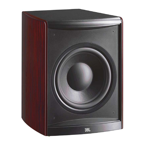
- Page 1 ™ Series LS120P Amplifier/Subwoofer SERVICE MANUAL JBL Consumer Products 250 Crossways Park Dr. Woodbury, New York 11797 Rev0 4/2008 Released 2008 Discontinued XXXX...
-
Page 2: Table Of Contents
Weight: 57 lb/25.8kg JBL continually strives to update and improve existing products, as well as create new ones. The specifications and details in this and related JBL publications are therefore subject to change without notice. * The Peak Dynamic Power is measured by recording the highest center-to-peak voltage measured across the output of a resistive load equal to minimum impedance of the transducer, using a 50Hz sine wave burst, 3 cycles on, 17 cycles off. -
Page 3: Detailed Specifications
LS120P JBL LS Sub 250W Powered Sub Amp LINE VOLTAGE Yes/No Hi/Lo Line Nom. Unit Notes US 120vac/60Hz 108-132 Vrms Normal Operation EU 230vac/50-60Hz 207-253 Vrms Normal operation, MOMS Parameter Specification Unit QA Test Limits Conditions Notes Amp Section Type (Class AB, D, other) - Page 4 LS120P Parameter Specification Unit QA Test Limits Conditions Notes sec. AC Power Applied Power on Delay time Transients/Pops Amplifier activated by signal V-peak 0.5V @ Speaker Output presence at the Line input ATO Transient V-peak 0.8V @ Speaker Output AC Line cycled from OFF to Turn-on Transient V-peak 0.8V...
-
Page 5: Packing
LS120P... -
Page 6: Controls/Connections
LS120P CONTROLS AND CONNECTIONS REAR PANEL 0 Phase Switch 1 LFE/Normal Selector 2 Subwoofer-Level Control 3 Crossover Adjustment 4 Power Indicator 5 Line-Level/LFE Input 6 Power Switch LS120P... - Page 7 LS120P SYSTEM CONNECTIONS If you have a Dolby ® Digital or DTS ® receiver/processor with a low-frequency-effects (LFE) or subwoofer output: Set LFE/Normal switch to “LFE.” LS120P If your receiver/processor does not contain a Dolby Digital or DTS processor, but has subwoofer outputs: Set LFE/Normal switch to LS120P “Normal.”...
-
Page 8: Operation
In the event that your subwoofer ever needs service, contact your local JBL AUTO ON/STANDBY dealer, or visit www.jbl.com for a service center near you. -
Page 9: Exploded View/Parts List
Trim Ring 333-000-05681 Felt Gasket 352-FM04020D605-E Screw, amplifier 30PR14FZD-DW01-E 12” Woofer Not for Sale LS120P Cabinet Not for Sale Damping 249HIPS-05093-0BAE Port Tube Not for Sale LS120P Amplifier 357-XM08186-E Insert, Copper 327-010-05037-0BAE Grille Cup 316-CU-05289-0BAE JBL Logo 320-RUB-05160-0BAE Rubber Feet... -
Page 10: Test Set-Up And Procedure
LS120P LS120P Test Set Up and Procedure SYSTEM AURAL SWEEP TEST Equipment needed: • Function/signal generator/sweep generator • Integrated Amplifier • Multimeter • Speaker cables General Unit Function (UUT = Unit Under Test) Switches/knobs on the amplifier faceplate: LFE/Normal to "Normal" Low Pass Frequency Adjust full CW (150Hz) Phase switch –... -
Page 11: Amplifier Block Diagram
LS120P... - Page 12 LS120P...
-
Page 13: Detailed Troubleshooting
LS120P LS120P(UL) AMP Troubleshooting Flow Chart AMP no signal out Check fuse, transformer, D123.D124 etc DC voltage check ±Vcc Check Q116,Q117,Q118,,D122 Check +/-15v LED red LED light Green or red Check,Q102,101,U103 etc LED light Green Check U101,R233,286 , Check U105 U102, etc Check P104 pin8 signal Pin7 signal... -
Page 14: Drawings
LS120P... - Page 15 LS120P...
- Page 16 LS120P...
- Page 17 LS120P...
- Page 18 LS120P...
-
Page 19: Electrical Parts List
LS120P LS120P Electrical Parts List Part number Description Qty Reference Designator INPUT/PREAMP PCB & DAUGHTER BOARD PCB Resistors 110-14392J26-E CARBON RESISTOR 3.9K 1/4W ±5% CF (RoHS) R150, 110-16000j26-e CARBON RESISTOR 0Ω 1/6W ±5% CF (RoHS) R191, 110-16101J26-E CARBON RESISTOR 100Ω 1/6W ±5% CF (RoHS) R112,R113,R151,R152, 110-16102J26-E CARBON RESISTOR 1K 1/6W ±5% CF (RoHS) - Page 20 LS120P Part number Description Qty Reference Designator INPUT/PREAMP PCB & DAUGHTER BOARD PCB 135-3226M50-E ELECTROLYTIC CAP.22U 50V ±20% (RoHS) C151, 139-3227M16-E LOW LEAKAGE EC 220uF 16V±20% (RoHS) C131, 129-A223J633-E METALIZE CAP. 0.022U 63V ±5% MSC (RoHS) C150 Semiconductors 192-027c1815gr-e transistor 2SC1815GR TOSHIBA(RoHS) NPN Q101,Q102,Q103, 197-631n4148-e DIODE 500mW 75V 1N4148 Panjit (RoHS)
- Page 21 LS120P Part number Description Qty Reference Designator MAIN PCB Semiconductors IC TL431CLP (RoHS) PROGRAMMABLE PRECISION 190-16L431CLP1-E D115, REFERENCE 192-027c1815gr-e transistor 2SC1815GR TOSHIBA(RoHS) NPN Q110,Q112,Q114,Q117, 192-028a1015gr-e transistor 2SA1015GR TOSHIBA(RoHS) PNP Q111,Q113,Q115, 192-1572N5551-E transistor FSC 2N5551 (RoHS) NPN Q109, 192-1582N5401-E transistor FSC 2N5401 AI-PNP 350V500mA TO-92 (RoHS) Q108, 197-631n4148-e DIODE 500mW 75V 1N4148 Panjit (RoHS)
- Page 22 LS120P Part number Description Qty Reference Designator CLASS D PCB ASS'Y (RECOMMENDED REPLACE ENTIRE MODULE PART# 051-A05022C-E) 192-09210376qs-e SMD TRANSISTOR 2SA1037K-T146Q/RROHM (RoHS) Q7,Q9, 192-09215146rs-e SMD TRANSISTOR 2SA1514K-T146R ROHM(RoHS) 192-1582N5401-E TRANSISTOR FSC 2N5401 AI-PNP 350V500mA TO-92 (RoHS Q6B, 192-232irf9640-e FET IRF9640 IR P-CH TO220(RoHS) Q10,Q10B, 192-233F640N-E TRANSISTOR IRF640N INTERNATIONAL(RoHS)
-
Page 23: Ic/Transistor Pinouts
LS120P... -
Page 24: Schematics
LS120P... - Page 25 LS120P...
- Page 26 LS120P...
- Page 27 LS120P...
- Page 28 LS120P...
- Page 29 LS120P...
- Page 30 LS120P...
- Page 31 LS120P...
- Page 32 LS120P...
- Page 33 LS120P...
Need help?
Do you have a question about the LS Series and is the answer not in the manual?
Questions and answers