Table of Contents

Subscribe to Our Youtube Channel
Related Manuals for V-TUF VTS1210HPC XL


Summary of Contents for V-TUF VTS1210HPC XL
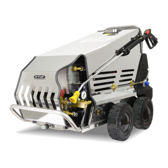
- Page 1 VTS1210HPC XL MOBILE HOT SITE PRESSURE WASHER Please read this manual before using the VTS1210HPC XL All Errors & Omissions Excused – Speci cation May Change Without Notice – Please Refer To www.v-tuf.co.uk For the Latest Version...
-
Page 2: Table Of Contents
CONTENTS Contents Page Important Safety Instructions General Points & Information Safety Norms & Usage Technical Data Identi cation Data Installation Cold & Hot Water Use Important Advice 17-18 Transport / Lifting / Storing Regulation of Start Electrodes 20-23 Troubleshooting 24-27 Electric Diagrams 27-28 Functionality... -
Page 3: Important Safety Instructions
High pressure cleaners must not be used by children or untrained personnel. High pressure hoses, fittings and couplings are important for the safety of the appliance. Use only hoses, fittings and couplings recommended by V-TUF. Always wear suitable eye, face and body protection. -
Page 4: General Points & Information
Should the manual be damaged, or missing any pages, please return it immediately to your reseller who will provide you with a replacement copy. Alternatively, you can download this document as a pdf from the website at v-tuf.com and search for this RAPID VTS1210HPC XL Mobile hot site pressure washer Conservation of the Manual This manual should be retained for the full working life of the machine. - Page 5 Delivery The transport will be carried out by qualified companies, in respect to regulations in force and legislation relative to weight and length. The merchandise travels under the full responsibility of the transporter and the user; in the event of an accident, or late delivery, the manufacturer accepts no liability.
- Page 6 Prior to use, please carefully read the instructions, paying particular attention to "IMPORTANT RECOMMENDATIONS", "SECURITY NORMS" and "PRECAUTIONS". It is forbidden to remove or tamper with the protective parts of the machine. It is forbidden to use inflammable, explosive or toxic substances. It is obligatory to use appropriate protective equipment.
- Page 7 When using the machine outdoors, do not use when it is raining Do not attempt any kind of maintenance whilst the plug is connected to any sort of power supply. Take care not to spray the machine with the water jet as this could lead to short-circuit Should you need to use an extension lead with the power supply, make sure that the connection between the extension lead and the power lead is secure and stable and conforms to standard safety norms.
- Page 8 It is strongly forbidden to carry out any operation with the machine if you are not wearing the appropriate safety equipment (protective glasses, gloves, overalls etc) as per established safety norms. During winter, and in the event of frost, it is advisable to use anti-freeze or to empty out the water from the internal circuits by closing the tap from the water supply and activating the machine until all of the water is expelled.
- Page 9 ATTENTION: The diameter (z) of the chimney (2) must not be less than that of the adaptor (1). It is advised to take steps to install a chimney to expel the machine fumes, as shown in the diagram. Usage in areas subject to winds or strong air currents ATTENTION: Where the machine is to be used in areas subject to wind or strong air currents, you should attach the chimney adaptor, our order code VTRPS5000030.
-
Page 10: Technical Data
TECHNICAL DATA: Industrial Speci cation - VTS1210HPC XL WORKING PRESSURE (BAR) MAX FLOW (L/MIN) PUMP TYPE SELF-PRIMING BOILER – CLEAN BURN DIESEL FIRED HOT WATER TEMP 0°C - 150°C STEAM STAGE TOTAL STOP SYSTEM DPS type CHEMICAL APPLICATION YES – high pressure... -
Page 11: Identi Cation Data
NUMBER: ATTENTION: Check that your VTS1210HPC XL high pressure washer has been provided with these identification details, if they have not been provided please inform your local dealer immediately. Machines which have not been provided with these details MUST NOT BE USED, and should be considered anonymous and potentially dangerous. - Page 12 Attach the lance to the high pressure hose (1) and the other end to the output connection (2). Fit the sheath (B) in order to protect the hydraulic connection and to avoid the risk of scalding by contact. The high pressure pump is supplied already full of lubricating oil. Attach a water tube (not supplied) to the entry connection (3) and the other end to the tap of the water source (4) which must be able to provide a minimum flow rate equal to that of the pump.
-
Page 13: Cold & Hot Water Use
COLD WATER USE 1. Check that the warning light ( c ) is lit, indicating that there is electric current within the machine. 2. Open the water source tap (2), then start the motor and pump by pressing the appropriate switch (in) on the control board. - Page 14 ATTENTION TSI SYSTEM If a water leak is detected, the machine will shut down and the appropriate warning light (f) will illuminate: check the high pressure water circuit in the machine and then reset the machine by pressing the switch (in).
- Page 15 USE WITH CHEMICAL PRODUCTS With the machine shut down, act the device (adjustable head) placed on the lance end to obtain the suction and the distribution of the product; pull the gun trigger to obtain the detergent distribution and start the work. ATTENTION During operation of the machine, it is obligatory to use the appropriate personal safety equipment.
-
Page 16: Important Advice
LUBRICATION OF THE PUMP For the models 200.15 we recommend: V-TUF Pressure Lube PL100 – OIL CAPACITY 1.2 litres For the models 100.12 we recommend: V-TUF Pressure Lube PL100 – OIL CAPACITY 0.42 kg You should change the oil after the first 50 hours of use, and after each subsequent 500 hours of... - Page 17 TRANSPORT – LIFTING – SHIFTING ATTENTION: Whenever the machine needs to be transported, it should be securely fixed with straps, cables or other suitable equipment in order to avoid accidental movement which could cause damage to people or property as well as to the machine itself. ATTENTION: Should the machine need to be lifted, it should be hooked or coupled by means of strips, or suitable lifting equipment which will safeguard the machine’s integrity.
- Page 18 STORAGE Park the machine on a flat surface. If the machine is not going to be used for an extended period of time, empty the water circuits and the fuel tank then cover the machine and store it in a place protected from atmospheric extremes.
- Page 19 REGULATION OF THE STARTER ELECTRODES For optimum machine performance, it is necessary to check that the starter electrodes are always arranged in the correct way, as indicated in the diagram. Checking the height in relation to the level of the head of the fuel nozzle. Resting the control bar on the head of the diesel nozzle, as indicated in the diagram, check that the two electrodes do not go beyond the main wire.
- Page 20 Cleaning Applications MARKET SECTOR APPLICATIONS Automotive Cleaning Services, such as car washes, and vehicle cleaning in yards like courier’s fleet of trucks and vans. Public Sector Cleaning outside of hotels and other public eating areas, including car parks, and entrance steps to buildings. Construction Industry Cleaning the outside of buildings, concrete &...
-
Page 21: Troubleshooting
Troubleshooting PROBLEMS CAUSES SOLUTIONS The pump turns but does not The pump is sucking in air. Check that the piping is watertight reach the required pressure Worn out valves Replace the valves Worn out valve seat Replace the valve seat Worn out or inadequate water nozzle Replace the water nozzle Worn out gaskets... - Page 22 Presence of water in the pump Worn out oil seal. Replace the oil seal. High percentage of humidity on the Change the oil twice as often as is air. normally prescribed. Gaskets are completely worn out. Replace the gaskets. Excessive noise Air is being sucked in.
- Page 23 Oil discharge from between the Worn out oil seals. Replace the oil seals. pump body and the pump head. Excessive vibrations. Worn out or dirty valves. Replace the valves. The engine does not start. There is no fuel in the tank. Ensure the fuel tank has the correct fuel.
- Page 24 HYDRAULIC DIAGRAM Water Tap T.a. Water Suction Tube Filter Detergent Filter T.a.d. Detergent Suction Tube Water Pump t.m. Delivery Tube Boiler t.a.p. High Pressure Water Outlet Tube Lance...
-
Page 25: Electric Diagrams
ELECTRIC DIAGRAM - SINGLE PHASE 230V... - Page 26 ELECTRIC DIAGRAM – THREE PHASE 230V...
-
Page 27: Functionality
ELECTRIC DIAGRAM - THREE PHASE 400V FUNCTIONALITY: The high pressure water cleaner has an input for an On/Off switch for the machine, a switch to select between hot or cold water operation, a “diesel pressure switch” input to manage the lack of diesel, and an input for the water temperature thermostat and 2 inputs for the pressure switches PTP and PDV. - Page 28 S_LIN = Electric current light S_TSI = TSI LIGHT (Total Stop) S_H20 = Lack of water light S_GAS = Lack of fuel light RUNNING Connecting to the electric current, the current light illuminates. Pressing the ON/OFF button to On will start the machine which will run accordingly: STATE1 PTP->NO (0 Bar) PDV ->NC (0 Bar)
- Page 29 PUMP-MOTOR-VALVE PARTS DIAGRAM & LIST Item Code Description Item Code Description C0.0611/VTPS BY-PASS CONTROL SET W3 (for W Pump) C0.0611/VTPS VB75 VALVE (for XM PUMP) XHDM300 XHDM300 (240V) PUMP 3/8 MxM BSP ADAPTOR XHDM350 XHDM350 (415V) PUMP 150BAR 14/T 6125010 080 HOSE XHDM400 XHDM400 (415V) PUMP 200BAR...
- Page 30 FRAME ASSEMBLY PARTS DIAGRAM & LIST ITEM CODE DESCRIPTION 5210000 CHASSIS 5116010 ELECTRIC BOX 4400115CPL HEAVY DUTY WHEEL 5116011 STAINLESS STEEL COVER 4000085 LANCE HOLDER 4000080 RUBBER EDGEING 4100010 FUEL TANK 4100011 FUEL LID / CAP 1000540/1 5x10 SREW 1300200 M20 WASHER 1300440 4x40 SPLIT PIN...
- Page 31 BOILER PARTS DIAGRAM...
- Page 32 BOILER PARTS LIST ITEM CODE DESCRIPTION B5.0321 IGNITION CABLE 1000521 M4 x 8 SCREW D6.030 ELECTRODE 1000740 M4 NUT 1000230 1/8MF EXTENSION 3000040 ELECTRODE HOLDER 1000220 FUEL INJECTOR HOLDER T6.1.3580H FUEL INJECTOR 3000030 UPPER TOP COVER 3000050 DEFLECTOR 4000280 1000050 LEVER 1000080 RIVETS...
- Page 33 3100020 FAN HOUSING 1000645 M6 WASHER 1000510 6x10 SCREW 3000010 6000015 BOILER MOTOR 1000560 8x16 TCEI SCREW 4000070 COUPLING 2000010O/D SOLENOID VALVE COIL COIL CABLE 4000045 PRESSURE SWITCH COVER 2000445 FASTENER 6000001 1/8 FUEL PRESSURE SWITCH 6350011/D FUEL PUMP 1000479 HOSE FITTING 1000216 ¼”...
- Page 34 ELECTRIC BOX PARTS DIAGRAM Item 2:...
- Page 35 ELECTRIC BOX PARTS LIST ITEM CODE DESCRIPTION 19.5110 THERMOSTAT CONTOL PANEL LABEL 4280030 4600021 GASKET 4600022 O-RING 4000083 SPACER 2000113T 400V/ PCB BOARD 2000113M 230V / PCB BOARD 1000532 TAPPING SCREW 5400065 BRACKET A1382060 CIRCUIT BREAKER 2000446 TERMINALS 4100044 PLUG WIRE THERMOSTAT I2.084 RED LED LIGHT WITH LENS I2.085...
- Page 36 GRIP TRIGGER FIXED 350 BAR 3/8F IN x 1/4F B14.9191MSS MSQ DURAKLIX STAINLESS STEEL QR MALE PLUG 3/8” M T1.562NEW V-TUF KTQ FEMALE QR x 1/4M- PULL BACK (KEW TYPE) - NEW VITON T2.903 KTQ MALE x 1/4F SPIGOT ST/STEEL-MAX T2.091 900mm STAINLESS STEEL LANCE WITH BEND 1/4M x 1/4M - T2.091...
- Page 37 Super Series Pump XHDM300SS 12 litres/min 200 bar VTPKIT 134 XHDM300SS XHDM350SS VTPKIT 135 VTPKIT 137 VTPKIT 2 XHDM300SS LUBRICATION OF THE PUMP We recommend: VTUF PL100 – OIL CAPACITY 0.42 kg You should change the oil after the rst 50 hours of use, and after each subsequent 500 hours of operation.
Need help?
Do you have a question about the VTS1210HPC XL and is the answer not in the manual?
Questions and answers