Advertisement
Quick Links
Advertisement

Subscribe to Our Youtube Channel
Related Manuals for ESX VISION NAVICEIVER VN810 MZ-6


Summary of Contents for ESX VISION NAVICEIVER VN810 MZ-6
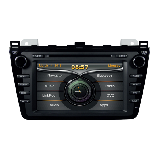
- Page 1 VN810 MZ-6...
- Page 2 INSTALLATION NOTES / Installationshinweise Important Notes prior to installation: This guide is an installation aid for a proper installation of the device. Please read the following instructions prior installation: 1.) Please treat all parts of the sound system and the components of your vehicle with caution. 2.) Follow under all circumstance the regulations of the vehicle manufacturer and do not make any modifications on the vehicle, which could interfere the driving safety.
-
Page 3: Table Of Contents
INDEX / Inhaltsverzeichnis Scope of delivery ..........................4 Lieferumfang ............................4 Connection Diagram ........................... 6 Anschlussdiagramm ..........................6 Installation notes ..........................7 Installationshinweise ..........................7 Installation example ........................... 9 Einbaubeispiel ............................9... -
Page 4: Scope Of Delivery
SCOPE OF DELIVERY / Lieferumfang ITEM FIGURE SLOT QUANTITY Artikel Abbildung Steckplatz Anzahl MAIN DEVICE – Hauptgerät STYLUS – Markierstift MICRO SD CARD 8GB INKL: NAVIGATION SOFTWARE – MicroSD Speicherkarte 8GB Navigationssoftware REMOTE CONTROL – Fernbedienung VIDEO INPUT CABLE SET Video-Eingang Kabelsatz REAR CAM INPUT Rückfahrkamera-Eingang... - Page 5 SCOPE OF DELIVERY / Lieferumfang ITEM FIGURE SLOT QUANTITY Artikel Abbildung Steckplatz Anzahl AUDIO OUT (SUBWOOFER/CENTER) Audio-Ausgang (Subwoofer/Center) USB CABLE SET WITH 2 CONNECTORS USB Kabelsatz mit 2 Anschlüssen IPOD / IPHONE CONNECTOR iPod / iPhone Anschluss BT-MICROPHONE BT-Mikrofon GPS ANTENNA GPS Antenne HANDBRAKE CONNECTION &...
-
Page 6: Connection Diagram
CONNECTION DIAGRAM / Anschlussdiagramm BT-MICROPHONE BT-Mikrofon AUDIO OUT (DUAL ZONE) Audio-Ausgang (Dual Zone) AUDIO OUT (SUBWOOFER/CENTER) WITH REMOTE TURN ON Audio-Ausgang (Subwoofer/Center) mit Einschaltleitung „Remote“ VIDEO INPUT CABLE SET Video-Eingang Kabelsatz FRONT CAM INPUT (optional) Frontkamera-Eingang (optional) SPECIFIC CONNECTOR OF THE VEHICLE Fahrzeugspezifischer Stecker WITHOUT FUNCTION AM/FM ANTENNA... -
Page 7: Installation Notes
Vermeiden Sie das Verlegen des Kabels über die Lenksäule. In der Regel sollte das Kabel lang genug sein, um die A-Säule (Fahrerseite) über die Beifahrerseite zu erreichen. Ein evtl. werksseitig vorhandenes Mik- rofon ist nicht kompatibel mit dem ESX Gerät. Bitte verwenden Sie das mit- gelieferte Mikrofon. -
Page 8: Installationshinweise
INSTALLATION NOTES / Installationshinweise Handbrake connection: Connect the cable from the handbrake connection (14) with the handbrake signal in your vehicle. The signal must be connected with ground while the handbrake is applied. Please contact for a proper and safe installation your car dealer! According to legal regulations, the device must playback a DVD or video on the main screen only with the handbrake applied, Never connect the the cable permanently with the vehicle‘s ground. -
Page 9: Installation Example
INSTALLATION EXAMPLE / Einbaubeispiel 1.) Unlock the damper of the glove box and carefully flap down the glove box. 1.) Entriegeln Sie den Dämpfer des Handschuhfachs und klappen Sie das Handschuhfach vorsichtig runter. 2.) Loosen now the decoration panel. Remove before the cupholder in the center console. 2.) Lockern Sie jetzt die Zierblende. -
Page 10: Einbaubeispiel
INSTALLATION EXAMPLE / Einbaubeispiel 5.) Now remove the decoration panels from the dash board on each side. 5.) Nun entfernen Sie die Zierblenden des Armaturenbretts auf jeder Seite. 6.) Un-screw the shift knob. 6.) Schrauben Sie den Schaltknauf ab. 7.) Remove the inner decoration panel of the AC controller unit and lay it aside without unplugging the connectors. - Page 11 INSTALLATION EXAMPLE / Einbaubeispiel 9.) Pull out the AC controller unit and let it hang out of the bay. 9.) Ziehen Sie die Klimasteuerung heraus und lassen diese aus dem Schacht hängen. 10.) Loosen the panel of the ventilation unit. 10.) Lockern Sie die Blende der Lüftereinheit.
- Page 12 Kabelstecker an der Radioeinheit. Dann legen Sie dann die Radioeinheit beiseite. 14.) Lay the connection cable sets of new ESX device (refer to page 4-5) inside the vehicle to the desired location. 14.) Verlegen Sie nun die Anschlusskabel des neuen ESX Geräts (siehe S.
- Page 13 INSTALLATION EXAMPLE / Einbaubeispiel 17. Before you complete the installation of the new ESX device, check its function. Please note that it may take up to 15 minutes, until a GPS signal can be received (in the open). After the successful check of the functions, re-assemble the new device in the reverse order (steps 1-12).
- Page 14 NOTES / Notizen...
- Page 15 NOTES / Notizen...
- Page 16 ESX Car Media Systems · Audio Design GmbH Am Breilingsweg 3 · D-76709 Kronau/Germany Tel. +49 7253 - 9465-0 · Fax +49 7253 - 946510 www.esxnavi.de - www.audiodesign.de ©2017 All Rights Reserved...
Need help?
Do you have a question about the VISION NAVICEIVER VN810 MZ-6 and is the answer not in the manual?
Questions and answers