Advertisement
Quick Links
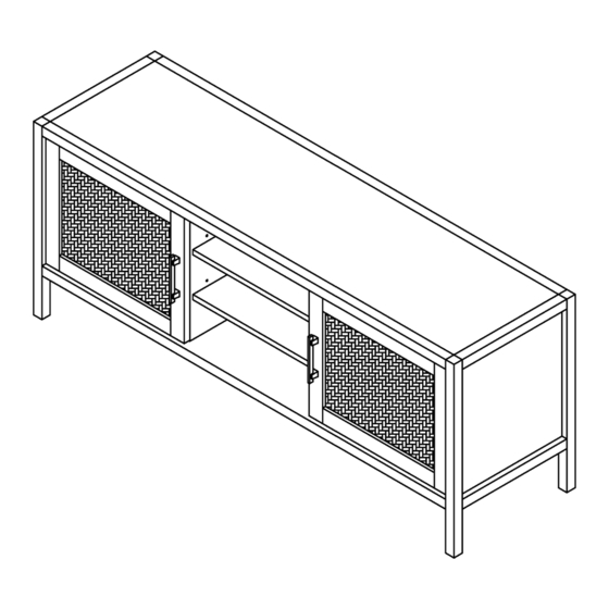
warwick
long & low media stand
style # FKWWLLMDBR (fawn brown)
dpci # 249-10-0090
TCIN # 79582394
style # FKWWLLMDBK (jet black)
dpci # 249-10-6116
TCIN # 79582396
style # FKWWLLMDWH (oxford white)
dpci # 249-10-6083
TCIN # 79582395
style # FKWWLLMDNT (natural)
dpci # 249-10-0096
TCIN # 80888059
>> assembly instructions
© 2020 Target. The Bullseye Design is a trademark of Target Brands, Inc. All rights reserved.
Advertisement

Subscribe to Our Youtube Channel
Related Manuals for Target warwick 249-10-0090


Summary of Contents for Target warwick 249-10-0090
- Page 1 # FKWWLLMDWH (oxford white) dpci # 249-10-6083 TCIN # 79582395 style # FKWWLLMDNT (natural) dpci # 249-10-0096 TCIN # 80888059 >> assembly instructions © 2020 Target. The Bullseye Design is a trademark of Target Brands, Inc. All rights reserved.
- Page 2 Congratulations on your latest Target purchase. Now what? Don’t start sweating over this box of parts. This will be easy. We did the hard work for you. All you need to do is follow our simple instructions and you’ll be on your way to transforming your room in no time.
- Page 3 table of contents introduction hardware parts list how to use the cam lock system assembly 7-16 how do adjust door alignment how to adjust the door hinges QUESTIONS? Just call 1-855-MYTGTHOME (855-698-4846) for parts and service. For faster service, have the style number and dpci number ready when calling.
- Page 4 hardware (H1) x 16 (H2) x 16 (H3) x 16 (H4) x 16 (H5) x 2 wooden dowel cam bolt shelf support pull (H6) x 4 (H7) x 23 (H8) x 1 (H9) x 1 (H10) x 1 pull bolt short pan head screw wall anchor wall screw...
- Page 5 exploded diagram ITEM DESCRIPTION QUANTITY top panel left side panel right side panel bottom panel back panel partition center adjustable shelf side adjustable shelf door center foot...
- Page 6 how to use the cam lock system Screw cam bolt into panel Align cam bolt(s) with cam(s) Push cam into panel - arrow feature and insert all the way into on cam top points to panel edge cross-bored hole(s) Rotate cam(s) clockwise 180° to Panels should be tight against each lock panels together other and connection should be rigid...
- Page 7 step 1: attach partitions to bottom panel finished edge (H1) x 4 (H2) x 4 (H3) x 4 wooden dowel cam bolt 1.1. Carefully tap small wooden dowels into place in bottom panel. Leave 1/2” of the dowels sticking out. 1.2.
- Page 8 step 2: attach top panel finished edge (H1) x 4 (H2) x 4 (H3) x 4 wooden dowel cam bolt finished edge 2.1. Screw-In cam bolts must be screwed down flush in top panel. 2.2. Carefully tap small wooden dowels into place in top panel. Leave 1/2” of the dowels sticking out. 2.3.
- Page 9 step 3: attach left side panel (H1) x 4 (H2) x 4 (H3) x 4 wooden dowel cam bolt 3.1. Screw-In cam bolts must be screwed down flush in left side panel. 3.2. Carefully tap small wooden dowels into place in left side panel. Leave 1/2” of the dowels sticking out. 3.3.
- Page 10 step 4: attach right side panel (H1) x 4 (H2) x 4 (H3) x 4 wooden dowel cam bolt 4.1. Screw-In cam bolts must be screwed down flush in right side panel. 4.2. Carefully tap small wooden dowels into place in right side panel. Leave 1/2” of the dowels sticking out. 4.3.
- Page 11 step 5: attach back panel and center foot **FAILURE TO FOLLOW ALL DIRECTIONS ON THIS PAGE MAY RESULT IN UNEVEN DOOR ALIGNMENT** hole for anti-tip Begin by installing all of the screws along one edge of the back panel. Next, using a square or tape measure, make sure that the cabinet is square.
- Page 12 step 6: install adjustable shelves (H4) x 16 shelf support 6.1. Insert shelf supports into desired hole. Different holes accommodate different shelf heights. 6.2. Angle shelf to fit between the rails and set on top of shelf supports.
- Page 13 step 7: attach hinges to doors (H13) x 4 (H14) x 8 hinge flat head screw 7.1. Align screws with pre-drilled holes to attach hinges to doors. Do not over tighten screws.
- Page 14 step 8: attach doors to cabinet (H14) x 8 flat head screw 8.1. Align screws with pre-drilled holes to attach doors to cabinet. Do not over tighten screws.
- Page 15 step 9: attach door pulls (H5) x 2 (H6 ) x 4 pull pull bolt 9.1. Align bolts with pre-drilled holes to attach pulls to doors. Do not over tighten bolts.
- Page 16 step 10: install anti-tip kit (H8) Position against wall (H10) Mark position of strap hole on wall Drill 1/4” hole (H11) Tap in wall anchor (H12) (H12) (H9) Fasten anti-tip strap with wall screw provided (H11) x 1 (H10) x 1 (H8) x 1 (H9) x 1 (H12) x 2...
- Page 17 how to adjust door alignment Tips for proper door alignment: -Adjustable levelers will reduce minor door mis-alignments caused by an uneven floor. -Use a level to determine if the cabinet top is level. If not, start with the levelers retracted and adjust them as needed.To retract the levelers turn them counterclockwise.
- Page 18 1. WARNING - Death or serious injury may occur when children climb on audio and/or video equipment furniture. A remote control or toys placed on the furnishing may encourage a child to climb on the furnishing and as a result the furnishing may tip over on to the child. 2.
- Page 19 SALICE 600 Series Adjustment Instructions Height Adjustment is achieved by loosening the two screws indicated by the arrows. Once all plates are loosened, the door can be repositioned vertically. The screws are then tightened when the door is in the desired position. Depth Adjustment is achieved by loosening the center screw indicated by the arrow.
- Page 20 LIFETIME GUARANTEE AND LIMITED WARRANTY* Salice America, Inc., warrants that all hinges and/or Salice products contained in Quality That Lasts A Lifetime this product, (but not the product itself) against defects in material and workman- ship for as long as the original consumer purchaser owns the products. Salice will send the original consumer purchaser a new Salice hinge to replace any defective Salice hinge subject to this warranty without charge.
- Page 21 © 2020 Target. The Bullseye Design is a trademark of Target Brands, Inc. All rights reserved.
Need help?
Do you have a question about the warwick 249-10-0090 and is the answer not in the manual?
Questions and answers