
Related Manuals for Kentucky MD10D

Summary of Contents for Kentucky MD10D
- Page 1 MD10D Manual Gauge I N S T R U C T I O N M A N U A L Hymark Ltd. – 427 Bark cove– Owensboro, KY 42303 (270) 683-3500 – Fax (270) 683-2500 www.kentuckygauge.com...
-
Page 3: Table Of Contents
Table of contents 1. Product Description Intended use Caveats Work place Danger zone 2. Basic Safety Hints Notice hints inside manual Owner obligations Operator obligations Intended use 3. Installation Conveyor / Table installation Mounting guide rail 4. Basic Operation Stop operation Set Stop Position 5. -
Page 5: Product Description
Faceplate 1.1 Intended Use The only acceptable use for the MD10D is as a length gauging system. Never place any material on the conveyor/table except the piece to be cut. Any other use is not intended and is a misuse of the gauging system. -
Page 6: Danger Zone
1.4 Danger zones -The moving carrier -The area between the face plate or moving carrier and the saw, drill, puncher or any other machines These areas are always dangerous and have the potential to harm the operator or others. There are special safety precautions when working inside these areas. -
Page 7: Basic Safety Hints
2. Basic safety hints 2.1 Read and follow all hints inside the Instruction Manual Basic requirements for the correct use of the gauging system or the machine are the knowledge of the basic safety hints and the safety precautions. This instruction manual contains the most important safety hints. This instruction manual, especially the safety hints and precautions must be followed by every person working with this gauge or machine. -
Page 8: Installation
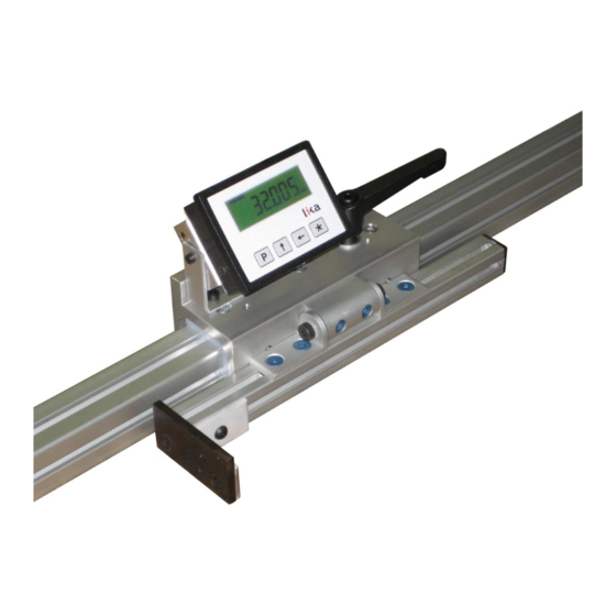
3. Installation Brake Handle Digital Readout Guide Rail Carriage Faceplate Setup conveyor/table (if purchased) Attach the guide rail to the conveyor/table with the supplied HDWE Slide on the carriage assembly and attach end bumper stops. **Carriage assembly may already be mounted onto guide rail.** Note: LCD displays is powered by 1 ‘C’... -
Page 9: Conveyor / Table Installation
3.1 Conveyor / Table Installation (optional, applicable if purchased) Assemble the conveyor legs to the appropriate height with the supplied nuts and bolts; typically the leg height is adjusted so that the height of the rollers or tabletop matches that of the machine bed of the saw, drill, etc. ... -
Page 10: Mounting Guide Rail
Once rail is aligned and holes are drilled (if necessary), mount rail to conveyor/table using the supplied M8 screws, washers, and t-nuts via the t- slot of the bottom side of the guide rail. *T-nuts may already be inserted into bottom side of guide rail. MD10D Table top... -
Page 11: Basic Operation
4. Basic Operation 4.1 Stop Operation Brake Handle Lock Release 4.2 Set Stop Position 1. Release brake (see above illustration) 2. Move stop to position using the digital display 3. Lock brake (see above illustration) -
Page 12: Maintenance Requirements
Maintenance jobs as described in this chapter may only be done by authorized and trained personnel. **Prior to any maintenance of the Kentucky Gauge or accessories, please ensure the machine is not in operation and corresponding equipment is in “off” position. -
Page 13: Cleaning Carriage
5.5 Cleaning the carriage Remove chips, grease and any items on the conveyor/table that would be deemed in the pathway of, or causing an unwanted obstruction of, the carriage/gang stop. This should be done several times per day if the machine is in heavy use. -
Page 14: Dro Operation
6 DRO Operation Program (programming/change parameters) UP (increase value of selected digit) Shift left (select digit) Save (save data 6.1 Setting Datum (Referencing the system) By setting the datum or referencing the system, the operator is setting up the system so that the distance from the stop face to the saw blade is correctly displayed on the digital readout. -
Page 15: Changing From Absolute To Incremental Measuring
6.4 Changing from Absolute Measuring to Incremental Measuring The display can be changed from absolute measuring (unit displays actual distance from saw blade) to incremental or relative measuring (unit displays distance from last position). Pressing the P and * buttons together toggles these modes. Note: INC is shown in the display when the unit is running in incremental mode. -
Page 16: Dro Paramter Mode
7. DRO Parameter Mode 7.1 Entering Parameter Mode Press P button for 3 seconds to enter setup mode. “SEtUP” will be shown in the display. Press button to enter Menu 1 (parameter mode) 7.2 Editing Parameters Press P button to select next Parameter and Parameter setting. Press * button to save entered values 7.3 How to exit Parameter Mode Press P button until you reach final parameter rESEt. - Page 17 <jump to parameter dd_n> Inch = inch display mode <jump to parameter Inch_F> * = save, P = next parameter dd_n Decimal digit number (0, 1, 2) __________ Sets the decimal point position. 0 = no decimal point 1 = one decimal (e.g. 1,0) 2 = two decimals (e.g.
- Page 18 Parameter description Factory Setting User Setting F_oFS Offset mode (on, oFF) __________ Enables offset modification function by pushing P and buttons together on = activated oFF = deactivated * = save, P = next parameter rEF Datum value (-999999, 999999) __________ Absolute reference value for encoder.
-
Page 19: Dro Dimensional Drawing
8. DRO Dimensional Drawing (in mm) 8.1 Technical Data LCD display 7 digits plus sign symbol , 11 mm high Battery 2 commonly available "C" size , 1.5V 700 μA Consumption Operating temperature 5°C to 50°C (32°F to 122°F) Operating Speed max. -
Page 20: Warranty
9 Warranty Hymark Ltd Co (henceforth Hymark), warrants this product for a period of twenty-four (24) months from the date of shipment. During the warranty period, under authorized return component parts to Hymark freight prepaid, the company will repair, or at its option, replace any part found to be defective in material or workmanship, without charge to the owner for parts, service labor, or associated customary shipping costs. - Page 22 LD14x • Avoid running the sensor cable near high User manual voltage power cables (e.g. drive cables). • Avoid mounting sensor head near capacitive or LD140-M7 + SM25 inductive noise sources such as relays, motors, and switching power supplies. LD141-M7-R-… LD142-M7-R-…...
- Page 23 LD14x 5 - Electrical connections 5.1 SM25 sensor (only LD140) Plug in the sensor's Mini-DIN connector (circular) on backside of the display <1° <3° 5.2 RS232 serial interface (only with option I1) Connect PC to LD14x with NULL MODEM COMPUTER AT CROSS OVER cable (9 pin female - 9 pin female) available in commerce.
- Page 24 LD14x 6 - Setup 6.2.4.1 Fractional offset display The fractional inch display mode allows to set offset 6.1 Key's function values (OFS) in the following way: digit blinking increases ” pushing key. → : UP (select value) digit blinking increases ”...
- Page 25 LD14x COn only with Unit = FrEE, dG1, dG2 6.3.3 Additional function of MENUE 1 Allows to set a free conversion factor to display F_mmI mm/inch function [yES, no] non-metric units or angles. Enables the mm/inch function (by pushing key) Valeu range: yES = enabled FrEE = 0,00001 - 1,00000...
- Page 26 LD14x OFS2 Offset2 value [-999999, 999999] 7 - RS232 serial interface (option I1) Second Offset value. This value is added to actual If the display is provided with RS232 serial interface, value and OFS1. the following commands can be used. * = save, P = next parameter, P for 3 s.
- Page 27 LD14x 7.2.1 Command list Measurement unit [0, 5] (below the device address is indicated with AD) |ADRUNI=X Sets the measurement unit and display mode. Zeroing of device address X=0→ dEC = decimal mode |00RSET X=1→ FrEE = display with conversion factor Address of all connected devices is set to zero (0).
- Page 28 LD14x Read mm/inch display mode Datum value modification [0, 1] |ADTMMI |ADRRFE=X Reads status of mm/inch display mode. Enables Datum value modification combination P and ). X=0→ mm, X=1→ inch Answer: ADTMMI:+0000000XCHKS X=0→ oFF, X=1→ on Answer: ADTRFE:+0000000XCHKS Incremental measurement function [0, 1] |ADRRLA=X Read Datum value modification Enables incremental measurement function (key...
- Page 29 LD14x Offset2 value [-999999, 999999] Rev. Man.Vers. Description 1^ issue |ADROF2=X SW + Manual update Sets Offset2 (OFS2) value (the value has resolution Chap.5 correction 0,01). Reset function correction (chap. 6.2.1) Answer: ADROF2:XCHKS Read Offset2 value |ADTOF2 Reads actual Offset2 value. Answer: ADTOF2:XCHKS Offset3 value [-999999, 999999] |ADROF3=X...
Need help?
Do you have a question about the MD10D and is the answer not in the manual?
Questions and answers