Table of Contents
Advertisement
Quick Links
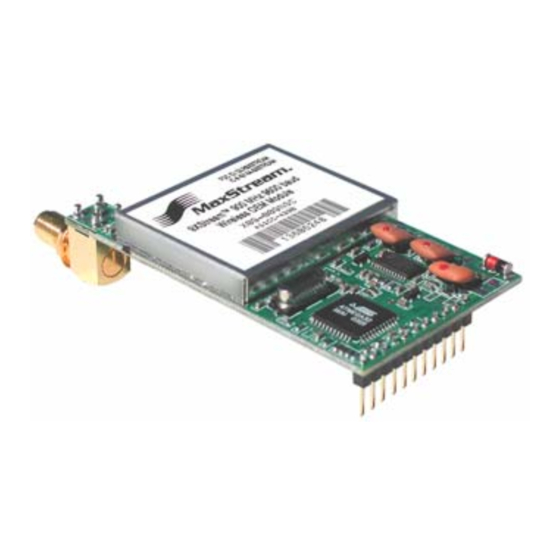
XStream™ OEM RF Module
XStream OEM RF Module
RF Module Operation
RF Module Configuration
RF Communication Modes
Appendices
Product Manual
For XStream OEM RF Module Part Numbers:
Reliable 900 MHz & 2.4 GHz OEM RF Modules by MaxStream, Inc.
355 South 520 West, Suite 180
Lindon, UT 84042
Phone: (801) 765-9885
Fax: (801) 765-9895
rf-xperts@maxstream.net
www.maxstream.net
v5.x00
X09-001...
X24-009...
X09-009...
X24-019...
X09-019...
XH9-001...
XH9-009...
XH9-019...
M100018
2006.02.24
Advertisement
Table of Contents

Subscribe to Our Youtube Channel
Related Manuals for MaxStream XStream XH9-019 Series


Summary of Contents for MaxStream XStream XH9-019 Series
- Page 1 For XStream OEM RF Module Part Numbers: X09-001… X24-009… XH9-001… X09-009… X24-019… XH9-009… X09-019… XH9-019… Reliable 900 MHz & 2.4 GHz OEM RF Modules by MaxStream, Inc. 355 South 520 West, Suite 180 Lindon, UT 84042 Phone: (801) 765-9885 Fax: (801) 765-9895 rf-xperts@maxstream.net M100018 www.maxstream.net 2006.02.24...
- Page 2 XStream™ OEM RF Module – Product Manual v5.x00 [2006.02.24] © 2006 MaxStream, Inc. All rights reserved The contents of this manual may not be transmitted or reproduced in any form or by any means without the written permission of MaxStream, Inc. XStream™ is a registered trademark of MaxStream, Inc. Technical Support: Phone: (801) 765-9885 Live Chat: www.maxstream.net E-Mail: rf-xperts@maxstream.net © 2006 MaxStream, Inc. Confidential and Proprietary ii ...
-
Page 3: Table Of Contents
Appendix B: Development Guide 2.1.1. UART-Interfaced Data Flow XStream OEM Development Kit Contents 52 2.1.2. Flow Control Interfacing Hardware 52 2.2. Modes of Operation 11 MaxStream RS-232/485 Interface Board 2.2.1. Idle Mode Adapters 2.2.2. Transmit Mode Antennas 2.2.3. Receive Mode Interfacing Protocols 57 2.2.4. -
Page 4: Xstream Oem Rf Module
Streaming, Repeater, Multi-Streaming & Acknowledged Modes supported 1.1.1. Worldwide Acceptance FCC Certified (USA) – Refer to Appendix A for FCC Requirements. Systems that include XStream Modules automatically inherit MaxStream Certifications ISM (Industrial, Scientific & Medical) frequency band Manufactured under ISO 9001:2000 registered standards 9XStream (900 MHz) OEM RF Modules are approved for use in US, Canada, Australia, Israel (and more). -
Page 5: Specifications
Integrated Wire (optional) ¼ wave monopole, 3” (7.62 cm) length, 1.9 dBi Gain Connector (optional) Reverse-polarity SMA or MMCX Impedance 50 ohms unbalanced Certifications (visit www.maxstream.net for complete list) FCC Part 15.247 OUR9XSTREAM OUR-24XSTREAM Industry Canada (IC) 4214A-9XSTREAM 4214A 12008... -
Page 6: Pin Signals
* Module has 10K Ω internal pull‐up resistor ** Module has 10K Ω internal pull‐down resistor *** Module has 100K Ω internal pull‐up resistor Note: When integrating the XStream Module with a Host PC Board, all lines that are not used should be left disconnected (floating). Table 1‐03. J2 Pin Signal Descriptions Module Pin Signal Name reserved J2 Pins are used primarily for mechanical stability and may be left disconnected. © 2006 MaxStream, Inc. Confidential and Proprietary 6 ... -
Page 7: Electrical Characteristics
Time that RX LED pin is 13.6 ms 25.6 ms driven high For B > 64, For B > 36, T = 26.9 ms T = 30.2 ms Channel Initialization Time 35.0 ms 35.0 ms 35.0 ms 35.0 ms © 2006 MaxStream, Inc. Confidential and Proprietary 7 ... - Page 8 Vcc = 5.5V, pin high µA Current I/O Pin (absolute value) IIL2 , DO (Vcc – VI) / 10 ** IIL3 CONFIG (Vcc – VI) / 47 ** IIH2 (Vcc – VI) / 10 ** * Reset pulse must last at least 250 nanoseconds ** VI = the input voltage on the pin © 2006 MaxStream, Inc. Confidential and Proprietary 8 ...
-
Page 9: Rf Module Operation
Each data packet consists of a start bit (low), 8 data bits (least significant bit first) and a stop bit (high). The following figure illustrates the serial bit pattern of data passing through the module. Figure 2‐02. UART data packet 0x1F (decimal number “31”) as transmitted through the XStream Module Example Data Format is 8‐N‐1 (bits – parity ‐ # of stop bits) © 2006 MaxStream, Inc. Confidential and Proprietary 9 ... -
Page 10: Flow Control
DO Buffer as long as (pin 5) is de-asserted. Software Flow Control (XOFF). XON/XOFF software flow control can be enabled using the FL (Software Flow Control) Command. This option only works with ASCII data. © 2006 MaxStream, Inc. Confidential and Proprietary 10 ... -
Page 11: Modes Of Operation
PK bytes were originally pending in the DI buffer or if more bytes arrived from the UART after the transmission began. If more data is pending, the transmitting module assembles a subsequent packet for transmission. © 2006 MaxStream, Inc. Confidential and Proprietary 11 ... - Page 12 Check) is computed for the transmitted data and attached to the end of each RF packet. On the receiving end, the receiving module computes the CRC on all incoming RF data. Received data that has an invalid CRC is discarded [See Receive Mode section, next page]. © 2006 MaxStream, Inc. Confidential and Proprietary 12 ...
-
Page 13: Receive Mode
(SM = 3-8) LH, PW when sleeping Note: The cyclic sleep time interval must be forced into Idle Mode shorter than the “Wake-up Initializer Timer” if PW (Pin Wake-up) (set by LH Command). Command is issued. For more information about Sleep Modes, refer to the individual commands listed in “Related Commands” column of the table. The SM command is central to all Sleep Mode configurations. © 2006 MaxStream, Inc. Confidential and Proprietary 13 ... - Page 14 For example: If SM=4 (Cyclic 1.0 second sleep), the LH Parameter should equal 0x0B (“1.1” seconds). With these parameters set, there is no risk of the receiving module being asleep for the duration of wake-up initializer transmission. “Cyclic Scanning” explains in further detail the relationship between “Cyclic Sleep” and “Wake-up Initializer Timer” © 2006 MaxStream, Inc. Confidential and Proprietary 14 ...
- Page 15 Figure 2‐08. Correct Configuration (LH > SM) Length of the wake‐up initializer exceeds the time interval of Cyclic Sleep. The receiver is guaranteed to detect the wake‐up initializer and receive the accompanying payload data. Figure 2‐09. Incorrect Configuration (LH < SM) Length of wake‐up initializer is shorter than the time interval of Cyclic Sleep. This configuration is vulnerable to the receiver waking and missing the wake‐up initializer (and therefore also the accompanying payload data). © 2006 MaxStream, Inc. Confidential and Proprietary 15 ...
-
Page 16: Command Mode
(If using a MaxStream XIB-R Interface Board, the same result can be achieved by keeping the configuration switch pressed while turning off, then on again the power supplying the... - Page 17 For the XStream Module to recognize a binary command, RT (DI2 Configuration) Command must be issued. If binary programming is not enabled (RT ≠ 1), the module will not recognize that the CMD pin (Pin 5) is asserted and therefore will not recognize the data as binary commands. © 2006 MaxStream, Inc. Confidential and Proprietary 17 ...
-
Page 18: Rf Module Configuration
Command Mode section [p16]. 3.1.1. AT Command Example To Send AT Commands (Using the Terminal tab of MaxStream’s X-CTU Software) Example: Both of the following examples change the module’s destination address to 0x1A0D and save the new address to non-volatile memory. -
Page 19: Command Reference Table
Transmit Error Count 0 – 0xFFFF Diagnostics TT v4.22* 0x1A (26d) Streaming Limit 0 – 0xFFFF [0 = disabled] Networking & Security 0xFFFF 0x14 (20d) Firmware Version 0 x 0xFFFF [read-only] Diagnostics 0x08 (8d) Write (Special) * Firmware version in which command and parameter options were first supported. NOTE: AT Commands issued without a parameter value will return the currently stored parameter. © 2006 MaxStream, Inc. Confidential and Proprietary 19 ... -
Page 20: Xstream Command Descriptions
BD register. For example, a rate of 19200 bps can be set by sending the following command line "ATBD4B00". NOTE: When using MaxStream’s X-CTU Software, non-standard interface data rates can only be set and read using the X-CTU ‘Terminal’ tab. - Page 21 Sequence activates AT Command Mode (from Number of bytes returned: 1 Idle Mode). Related Commands: AT (Guard Time After), BT (Guard Time Before) Refer to the AT Commands section [p16] to view the default AT Command Mode sequence. © 2006 MaxStream, Inc. Confidential and Proprietary 21 ...
- Page 22 “CONNECTXXXX” string is sent to the host of the Parameter Configuration base module. “XXXX” is the MY (Source Address) enable of the connected remote module. disable Default Parameter Value: 0 Number of bytes returned: 1 Minimum Firmware Version Required: 4.30 © 2006 MaxStream, Inc. Confidential and Proprietary 22 ...
- Page 23 If MD = 1, the base MD (RF Mode) module will force the disconnection of an Minimum Firmware Version Required: 4.30 exclusive connection. If MD = 2, the remote module will send a “Disconnect Request Packet” to the base module. © 2006 MaxStream, Inc. Confidential and Proprietary 23 ...
- Page 24 Related Commands: GD (Receive Good Count) Once the receive error count reaches its maximum value (up to 0xFFFF), it remains at its maximum count value until the maximum count value is explicitly changed or the module is reset. © 2006 MaxStream, Inc. Confidential and Proprietary 24 ...
- Page 25 Related Commands: DT (Destination Address), network uses a different hopping sequence. ID (Module VID), MK (Address Mask) Different channels can be used to prevent modules in one network from listening to transmissions of another. © 2006 MaxStream, Inc. Confidential and Proprietary 25 ...
- Page 26 Number of bytes returned: 2 must be enabled for the update to take place. Related Commands: BK (Serial Break Passing), BO (Serial Break Timeout), CO (DO3 Timeout), DR (Disconnect), RT (DI2 Configuration), TO (DO2 Timeout) Minimum Firmware Version Required: 4.30 © 2006 MaxStream, Inc. Confidential and Proprietary 26 ...
- Page 27 (All “0” values are treated as “irrelevant” values and are ignored.) Refer to the Addressing Options section [p36] for more information. © 2006 MaxStream, Inc. Confidential and Proprietary 27 ...
- Page 28 Minimum Firmware Version Required: 4.30 Characters) parameter. RB must always be less than or equal to PK. If PK is changed to a value less than the current value of RB, RB is automatically lowered to be equal to PK. © 2006 MaxStream, Inc. Confidential and Proprietary 28 ...
- Page 29 If two modules attempted to transmit at the same time, the random time delay after packet failure would allow one of the two modules to transmit the packet successfully, while the other would wait until the channel opens up to begin transmission. © 2006 MaxStream, Inc. Confidential and Proprietary 29 ...
- Page 30 Command, the transmitter will transmit the original packet again. The packet will be transmitted repeatedly until an acknowledgement is received or until the packet has been sent RR times. Note: For retries to work correctly, all modules in the system must have retries enabled. © 2006 MaxStream, Inc. Confidential and Proprietary 30 ...
- Page 31 AT Command: ATSH <Diagnostics> Set/Read the serial number high word of the module. Binary Command: 0x25 (37 decimal) Parameter Range: 0 – 0xFFFF [read-only] Number of bytes returned: 2 Related Commands: SL (Serial Number Low) Minimum Firmware Version Required: 4.27C © 2006 MaxStream, Inc. Confidential and Proprietary 31 ...
- Page 32 Number of bytes returned: 2 receiving). This command can only be used if Related Commands: SM (Sleep Mode), LH (Wake-up Initializer Timer), HT (Time before Cyclic Sleep or Serial Port Sleep Mode settings Wake-up Initializer) have been selected using the SM command. © 2006 MaxStream, Inc. Confidential and Proprietary 32 ...
- Page 33 Minimum Firmware Version Required: 4.22 not successfully received and have been dropped. The TR parameter is not non-volatile and therefore is reset to zero each time the module is reset. © 2006 MaxStream, Inc. Confidential and Proprietary 33 ...
- Page 34 (Parameter values remain in the module’s memory until overwritten by future use of WR Command). If changes are made without writing them to non-volatile memory, the module reverts back to previously saved parameters the next time the module is powered-on. © 2006 MaxStream, Inc. Confidential and Proprietary 34 ...
-
Page 35: Rf Communication Modes
Acknowledged Mode [p41], Multi-Streaming Mode [p43] Peer-to-Peer Modules remain synchronized without use of a master/server. Each module shares the roles of master and slave. MaxStream’s peer-to- Definition peer architecture features fast synch times (35ms to synchronize modules) and fast cold start times (50ms before transmission). -
Page 36: Addressing
“ANDed” with the Address Mask of the RX module. Figure 4‐03. Address Recognition (Receiving Module) TX_DT = Transmitter Destination Address RX_DT = Receiver Destination Address RX_MY = Receiver Source Address NOTE: For more information regarding addressing and masks, refer to Application Note ‘XST- AN004b’. (Located on the MaxStream CD and on the web: www.maxstream.net) © 2006 MaxStream, Inc. Confidential and Proprietary 36 ... -
Page 37: Basic Communications
0 and (RN-1) if the local (i.e. receiving module’s) RN parameter is set to a non-zero value. These delays are intended to lessen congestion following long bursts of packets from a single transmitting module, during which several receiving modules may have become ready to transmit. © 2006 MaxStream, Inc. Confidential and Proprietary 37 ... -
Page 38: Repeater Mode
When in Repeater Mode, the network repeats each message among all available nodes exactly one time. This mechanism eliminates the need for configuring specific routes. The network is self- organizing and self-healing so that the system is able to receive transmissions in the event of a module going down. Figure 4‐05. Sample Repeater Network Topology © 2006 MaxStream, Inc. Confidential and Proprietary 38 ... - Page 39 Where L is the length of the transmitted packet in milliseconds, DS is the number of delay slots to wait, RSSI is the received signal strength in dBm, RN is the value of the RN register and RandomInt(A,B) is a function that returns a random integer from A to B-0 © 2006 MaxStream, Inc. Confidential and Proprietary 39 ...
- Page 40 32 byte packet in 12 ms for a round trip with UART transfer times of ~30ms or 33 polls per second (1066 bytes per second) with no repeaters. With two repeaters the time would be ~100ms round trip time for 10 polls per second or 320 bytes per second network throughput with two repeaters. © 2006 MaxStream, Inc. Confidential and Proprietary 40 ...
-
Page 41: Acknowledged Communications
Idle Mode and may receive RF data. This can have the effect of increasing the back-off delay, as the radio ca nnot return to RF transmit (or retransmit) mode as long as it is receiving RF data. © 2006 MaxStream, Inc. Confidential and Proprietary 41 ... - Page 42 0 and (RN-1), if the local RN parameter is set to a nonzero value. These delays are intended to lessen congestion following long bursts of packets from a single transmitting module, during which several receiving modules may have themselves become ready to transmit. © 2006 MaxStream, Inc. Confidential and Proprietary 42 ...
-
Page 43: Multi-Streaming Mode
CGP (Connection Grant Packet) is broadcast to all remote modules in the network to communicate the base in engaged in an exclusive connection. Upon receipt of the CGP notification, remote modules will wait for a DGP (Disconnect Grant Packet) before attempting again to send data to the base module. © 2006 MaxStream, Inc. Confidential and Proprietary 43 ... - Page 44 DI3 line high. If no connection is active, the de-assertion is ignored. A remote will request a disconnect if DI3 is de-asserted and the remote is currently connected the base. Refer to DR (DI3 Configuration) Command. A remote or a base module receives the ATDC (Disconnect) Command. © 2006 MaxStream, Inc. Confidential and Proprietary 44 ...
- Page 45 CGP and DGP packets will be sent RR times to begin and end the global connection resp ectively. The connection can be terminated by CE, CB timers, DI3 or ATD C Command as any other connections. © 2006 MaxStream, Inc. Confidential and Proprietary 45 ...
- Page 46 A base module can also be set t o send the “CONNECT XXXX” string (where “XXXX” is the connecting module’ s MY (Source Address) p arameter) anytime a connection is established. Refer to CM (Connectio n Me ssage ) Command. © 2006 MaxStream, Inc. Confidential and Proprietary 46 ...
-
Page 47: Appendix A: Agency Certifications
IMPORTANT: The 9XStream (900 MHz) and 24XStream (2.4 GHz) OEM Modules have been certified b the FCC for use with other products without any further certification (as per FCC section 2.1091). Changes or modifications not expressly approved by MaxStream could void the user’s authority to operate the equipment. -
Page 48: Oem Labeling Requirements
FCC RF Exposure compliance. MaxStream Modules are pre-FCC approved for use in fixed base station and mobile applications. As long as the antenna is mounted at least 20 cm (8 in) from nearby persons, the applicatio n is considered a mobile application. -
Page 49: Fcc-Approved Antennas
Type Gain Application Min. Separation Distance Yagi 6.2 dBi Fixed/Mobile ** 20 cm Yagi 7.2 dBi Fixed/Mobile ** 20 cm MaxStream A09-Y8 Yagi 8.2 dBi Fixed/Mobile ** 20 cm Yagi 9.2 dBi Fixed/Mobile ** 20 cm Yagi 10.2 dBi Fixed/Mobile **... -
Page 50: European Compliance (2.4 Ghz Only)
EMC and safety . Files are l ocated in the ‘doc umenta tion’ folder of the MaxStream CD. Important Note MaxStream does no t list th e entire se t of standards that must be met for each c... -
Page 51: Europe (2.4 Ghz) Approved Antenna List
• Modulation: Frequency Shift Keying • Channel Spacing: 400 kHz • ITU Classification: 400KF1D • Output Power: 100 mW EIRP • Notified Body Number: 0891 Contact MaxStream (801) 765-9885 if additional information is required. Europ e (2.4 GHz) Approved Antenna List Table A‐03. -
Page 52: Appendix B: Development Guide
MaxStream developed proprietary interface boards to facilitate the connection between XStream OEM RF Modu les and serial devices. MaxStream has developed an interface board that supports e RS-232/485/422 protocols (MaxStream part number: XIB-R). he following section illustrates properties of the MaxStream XIB-R Interface Board. The axStream Interface board provides means for connecting the XStream Module to any node that has an available RS-232 or RS-485/422 connection. -
Page 53: Maxstream Rs-232/485 Interface Board
XStream™ OEM RF Module – Product Manual v5.x00 [2006.02.24] MaxStream RS-232/485 Interface Board B-01a. Power Switch Move the Power Switch to the on (up) position to power the Figure B‐01. Front View Interface Board. DIP Switch [B.2a] settings are only read during a power-up sequence. B-01b. LEDs The LED indicators visualize diagnostic status information. The module’s status is represented as follows:... - Page 54 Automatic DIP Switch Configurations Each time the module assembly (XStream Module mounted to an XIB-R Interface Board) is powered on, intelligence on t he MaxStream Interface Board sends AT Commands that program the module based on positions of the DIP Switch. Automatic configurations that take place d...
-
Page 55: Adapters
Part Number: JD2D3-CDL-A (Red, DB-9 M-F) The serial loopback adapter is used for range sting. During a range test, the serial loopback adapter configures the module assembly to function as a repeater by looping serial data back into the radio for retransmission. Figure B‐07. Serial loopback adapter and pinouts For use in RS‐485/422 systems: DB‐9 to RJ‐45 adapters are documented on p45. © 2006 MaxStream, Inc. Confidential and Proprietary 55 ... -
Page 56: Antennas
As a general rule, it is best to keep the RF cable as short as possible. All cables promote signal loss which is usually measured in dB loss per 100 ft. MaxStream provides LMR- 95 rated cables. Common cables and dB losses are included in this table: able B‐04. Potential Signal Strength Loss due to Antenna Cable Length ... -
Page 57: Interfacing Protocols
Clear-to-Se Provides flow control Optional p ower input that is connected internally t o the Ring Indicato posi tive lead of the front power conne ctor * Th e AT C ommand Reference provides as associative tag whe n using the AT commands to program the odule. “DI” stands for Data Input and “DO” for Data Output. © 2006 MaxStream, Inc. Confidential and Proprietary 57 ... - Page 58 XStream™ OEM RF Module – Product Manual v5.x00 [2006.02.24] Wiring Diagram: RS-232 DTE Device to a DCE Module Assembly Figure B‐10. RS‐232 DTE (male connector) device wired to an XStream Module Assembly (female connector) Wi ng Diagram: DCE Module Assembly to an RS-232 DCE Device Figure B‐11. XStream Module Assembly (female connector) wired to an RS‐232 DTE (male connector) device Sample Wireless Connection: DTE -------- Figure B‐12 Typical wireless connection used for serial communications between DTE and DCE devices © 2006 MaxStream, Inc. Confidential and Proprietary 58 ...
-
Page 59: 2-Wire) Operation
Transmit serial data to and from the T/R+ (TRB) Positive Data Line XStream Module Assembly Optional power input that is connected internally Power to the front power connector 1, 3, 4, 6, 7 not used Wi ing Diagram: RS-485 (2-wire) Half-Duplex Figure B‐16. XStream Module Assembly in an RS‐485 (2‐wire) half‐duplex environment © 2006 MaxStream, Inc. Confidential and Proprietary 59 ... -
Page 60: 4-Wire) & Rs-422 Operation
T+ (TB) Serial dat a sent from the XStream Module Asse mbly Data Line Optional power input that is connected internally Power to the front power connector 1, 4, 6 not used Wiring Diagram: RS-485 (4-wire) Half-Duplex Figure B‐20. XStream Module Assembly in an RS‐485 (4‐wire) environment © 2006 MaxStream, Inc. Confidential and Proprietary 60 ... - Page 61 (even though there are 8 wires). en using phone cabling (RJ-11) – Pi n2 in the cable maps to Pin3 on opposite end of cable and Pin1 map s to Pin4 res pectively. Figur e B ‐22 Mal e (yellow ) DB‐9 to RJ‐45 Ada pters igure B‐23. Female (green) DB‐9 to RJ‐45 Adapters © 2006 MaxStream, Inc. Confidential and Proprietary 61 ...
-
Page 62: X-Ctu Software
Install X-CTU software ble-click the "setup_X-CTU.exe" file and follow prompts of the installation screens. This file is loca ed in the ‘software’ folder of the MaxStream CD and also under the ‘Downloads’ sectio n of the following web page: http://www.maxstream.net/helpdesk/download.php... -
Page 63: Appendix C: Additional Information
XStream™ OEM RF Module – Product Manual v5.x00 [2006.02.24] Appendix C: Additional Information 1-Year Warranty XStream OEM RF Modules from MaxStream, Inc. (the ʺProductʺ) are warranted against defects in terials and workmanship under normal use, for a period of 1‐year from the date of purchase. In event of a product failure due to materials or workmanship, MaxStream will repair or replace the efective product. For warranty service, return the defective product to MaxStream, shipping repaid, for prompt repair or replacement. he foregoing sets forth the full extent of MaxStreamʹs warranties regarding the Product. Repair or replacement at MaxStreamʹs option is the exclusive remedy. THIS WARRANTY IS GIVEN IN LIEU F ALL OTHER WARRANTIES, EXPRESS OR IMPLIED, AND MAXSTREAM SPECIFICALLY ISCLAIMS ALL WARRANTIES OF MERCHANTABILITY OR FITNESS FOR A PARTICULAR PURPOSE. IN NO EVENT SHALL MAXSTREAM, ITS SUPPLIERS OR LICENSORS BE LIABLE FOR AMAGES IN EXCESS OF THE PURCHASE PRICE OF THE PRODUCT, FOR ANY LOSS OF USE, OSS OF TIME, INCONVENIENCE, COMMERCIAL LOSS, LOST PROFITS OR SAVINGS, OR OTHE R INCIDENTAL, SPECIAL OR CONSEQUENTIAL DAMAGES ARISING OUT OF THE USE R INABILITY TO USE THE PRODUCT, TO THE FULL EXTENT SUCH MAY BE DISCLAIMED BY LAW. SOME STATES DO NO T ALLOW THE EXCLUSION OR LIMITATION OF INCIDENTAL OR CONSEQUENTIAL DAMAGES. THEREFOR, THE FOREGOING EXCLUSIONS MAY NOT APPLY IN ALL CASES. This warranty provides specific legal rights. Other rights which vary from state to state may also apply. Orderin g Info rmation Figure C‐01 MaxStream OEM RF Module Part Numbers Key © 2006 MaxStream, Inc. Confidential and Proprietary 63 ... -
Page 64: Contact Maxstream
XStream™ OEM RF Module – Product Manual v5.x00 [2006.02.24] Contact MaxStream Free and unlimited technical support is included with every MaxStream Radio Modem sold. Please use the following resources for additional support: Documentation: http://www.maxstream.net/helpdesk/download.php Technical Support: Phone. (866) 765-9885 toll-free U.S. & Can (801) 765-9885 Worldwide Live Chat.
Need help?
Do you have a question about the XStream XH9-019 Series and is the answer not in the manual?
Questions and answers