Table of Contents
Advertisement
Repair
r
Ultra
Max II 695/795/1095t
Airless Sprayers
3300 psi (227 bar, 22.7 MPa) Maximum Working Pressure
Vac
Model
695
120
795
North America
1095
240
695
Europe
795
1095
240
695
Europe Multi-cord
795
1095
110
695
UK
795
1095
240
695
Asia & Australia
795
1095
100
695
Japan & Taiwan
795
1095
All models not available in all countries.
GRACO INC. P.O. BOX 1441 MINNEAPOLIS, MN 55440-1441
Copyright 2004, Graco Inc. is registered to I.S. EN ISO 9001
Standard/
Premium
Standard
248037
248036
Premium
248031
248030
Standard
248308
248038
Premium
248033
248032
Standard
248039
Premium
248034
248042
248041
248043
248044
248046
248045
248047
248048
248049
248050
248051
248058
248057
248059
248060
248053
248052
248055
248054
248056
309941
Rev. A
ti4281a
248036
Advertisement
Table of Contents

Related Manuals for Graco 248037


Summary of Contents for Graco 248037
- Page 1 Asia & Australia 248059 1095 248060 248053 248052 Japan & Taiwan 248055 248054 1095 248056 All models not available in all countries. GRACO INC. P.O. BOX 1441 MINNEAPOLIS, MN 55440-1441 Copyright 2004, Graco Inc. is registered to I.S. EN ISO 9001...
-
Page 2: Table Of Contents
Pressure Control Repair ....Graco Phone Number .... - Page 3 WARNING FIRE AND EXPLOSION HAZARD Flammable fumes, such as solvent and paint fumes, in work area can ignite or explode. To help pre- vent fire and explosion: D Use equipment only in well ventilated area. D Eliminate all ignition sources; such as pilot lights, cigarettes, portable electric lamps, and plastic drop cloths (potential static arc).
-
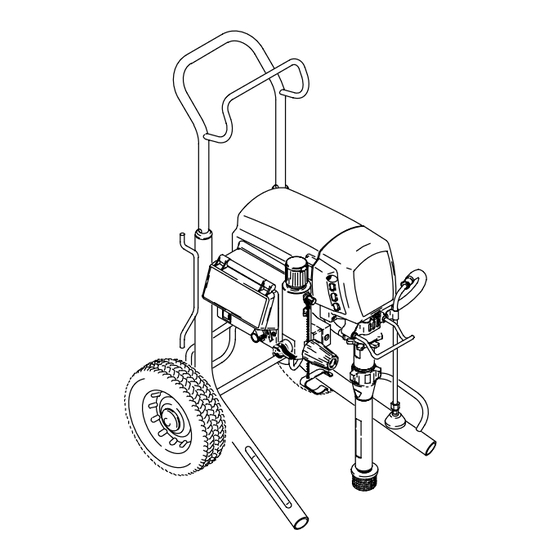
Page 4: Component Function And Identification
Component Identification and Function ti2377a ti4281a Fig. 1 Motor DC motor, permanent magnet, totally enclosed, fan cooled Drive Assembly Transfers power from DC motor to displacement pump Displacement Pump Transfers fluid to be sprayed from source through spray gun Fluid Outlet Spray gun is connected here Prime Valve Used to prime and drain sprayer (also relieves fluid outlet pressure) when open... -
Page 5: General Repair Information
General Repair Information Pressure Relief Procedure CAUTION To reduce risk of pressure control malfunction: WARNING Use needle nose pliers to disconnect wire. Never pull on wire, pull on connector. INJECTION HAZARD System pressure must be manually Mate wire connectors properly. Center flat blade of insulated male connector in female connector. -
Page 6: Troubleshooting
Troubleshooting Relieve pressure; page 5. Mechanical/Fluid Flow TYPE OF PROBLEM WHAT TO CHECK WHAT TO DO If check is OK, go to next check When check is not OK refer to this column Low Output or Pressure 1. For worn spray tip. 1. -
Page 7: Electrical
Troubleshooting Electrical Symptom: Sprayer does not run or stops running WARNING Relieve pressure; page 5. To avoid electrical shock or moving parts hazards when covers are removed for troubleshooting, wait 30 seconds after unplugging power cord for stored D Plug sprayer into correct voltage, grounded outlet electricity to dissipate. - Page 8 Troubleshooting Electrical DIGITAL CONTROL BOARD- INDICATION WHAT TO DO STATUS LIGHT DISPLAY Displays high – Improper pressure Open prime valve. Connect a known good trans- pressure ducer in place of the sprayer transducer. Set signal to contro when prime sprayer ON. Replace transducer If sprayer runs. valve is open Replace control board If sprayer does not run.
- Page 9 Troubleshooting Electrical DIGITAL CONTROL BOARD- INDICATION WHAT TO DO STATUS LIGHT DISPLAY E=05 Blinks 5 x repeat- Possible locked 1. Check motor wiring connections edly pump or drive. May be motor connection 2. Check for locked or frozen pump or drive train or wiring error.
-
Page 10: Pressure Control Repair
Pressure Control Repair Motor Control Board Removal Installation 1. Fig. 3. Apply small amount of thermal compound 110009 (5) to shaded component areas on rear of Relieve pressure; page 5. motor control board (95). CAUTION 2. Fig. 3. Remove four screws (38) and cover (96). To reduce risk of motor control board failure, do not overtighten screws (102) which can damage the 3. - Page 11 Pressure Control Transducer Removal 7. Remove grommet (40) from transducer and save for reuse. Relieve pressure; page 5. Installation 1. Install o-ring (20) and transducer (86) in filter base 2. Fig. 3. Remove four screws (38) and cover (96). (67). Torque to 35–45 ft-lb (47–61 N·m). 3.
-
Page 12: Drive And Bearing Housing Replacement
Drive and Bearing Housing Replacement 7. Remove five screws (6) and pull drive housing (90) CAUTION off motor (84). Do not drop gear cluster (89) when removing drive Assembly housing (90). Gear cluster may stay engaged in motor front end bell or drive housing. Fig. - Page 13 ti4253a Fig. 4 309941...
-
Page 14: Motor Replacement
Motor Replacement Removal Installation 1. Slide new motor (84) under two screws (23) in cart Relieve pressure; page 5. frame (62) near control. 2. Remove pump (91); Displacement Pump Re- 2. Install two screws (23) and nuts (19) on motor side opposite control. - Page 15 ti4254a LED Status Light Fig. 5 309941...
-
Page 16: Displacement Pump Replacement
Fig. 9 7. Fig. 6. Install pump rod shield (108) with screw 1.5 in. (31). 8. Fig. 10. Fill packing nut with Graco TSL until fluid flows onto top of seal. ti4258a Fig. 8 2. Install pump pin (44). Verify retaining spring (43) is ti4258a in groove of connecting rod (85). -
Page 17: 3-D Wiring Diagram
3-D Wiring Diagram ti4251a See Parts manual for wiring schematic Fig. 11 309941... -
Page 18: Technical Data
(57.2) Graco Phone Number TO PLACE AN ORDER OR FOR SERVICE, contact your Graco distributor, or call 1–800–690–2894 to identify the nearest distributor. All written and visual data contained in this document reflects the latest product information available at the time of publication.
Need help?
Do you have a question about the 248037 and is the answer not in the manual?
Questions and answers