Table of Contents
Advertisement
Quick Links
TCD220042AC_V2_MODI2
Safety Cat. 4,
Finger/Hand/Body Detection
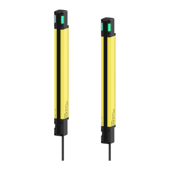
Safety Light Curtains
SFL / SFLA Series
PRODUCT MANUAL
For your safety, read and follow the considerations written in the instruction
manual, other manuals and Autonics website.
The specifications, dimensions, etc. are subject to change without notice for product
improvement. Some models may be discontinued without notice.
Features
• International safety standard and regulation compliance
: Type 4 ESPE (AOPD), SIL3, SIL CL3, Category 4, PL e, CE, UKCA, UL Listed, S-Mark,
KCs (industrial robot protection device)
• Available in 3 detection type models (finger, hand, hand-body detection) and various
protection height models
• Various safety-related functions & self-diagnosis functions
• Various status readings with 7-segment display and status indicators
• Easy beam adjustment with top and bottom beam indicators
• Upper OSSD indicator to check operation status and muting status (separate muting lamp
not required)
• 4 non-safety outputs for various applications (2 AUX, 2 lamp)
• Stable operation in diverse conditions including low temperature, oil, high pressure water
- Protection rating: IP65, IP67 (IEC standard), IP67G (JEM standard), IP69K (DIN standard)
- Ambient temperature: -30 to 60 ℃
• Additional functions and configuration available with dedicated software (atLightCurtain)
(SFLA Series)
ᜢ
ᜨ ᜪ
Safety Considerations
• Observe all 'Safety Considerations' for safe and proper operation to avoid hazards.
• symbol indicates caution due to special circumstances in which hazards may occur.
Warning
Failure to follow instructions may result in serious injury or death.
01. Fail-safe device must be installed when using the unit with machinery that may
cause serious injury or substantial economic loss. (e.g. nuclear power control,
medical equipment, ships, vehicles, railways, aircraft, combustion apparatus,
safety equipment, crime/disaster prevention devices, etc.)
Failure to follow this instruction may result in personal injury, economic loss or fire.
02. Do not use the unit in the place where flammable/explosive/corrosive gas, high
humidity, direct sunlight, radiant heat, vibration, impact, or salinity may be
present.
Failure to follow this instruction may result in explosion or fire.
03. Do not connect, repair, inspect, or replace the unit while connected to a power
source.
Failure to follow this instruction may cause malfunction or danger due to the safety-
related function that does not operate properly. For more information, please refer to laws,
regulations and standards in the country or region.
04. Do not disassemble or modify the unit.
Failure to follow this instruction may result in personal injury or fire. In addition, the
manufacturer does not guarantee the performance and functionality.
05. After 3 seconds of power input, use a machine or mechanical system.
Failure to follow this instruction may cause malfunction or danger due to the safety-related
function that does not operate properly.
06. Responsible person for use is an operator who:
- is fully knowledgeable about the installation, settings, use and maintenance of
the product.
- is familiar with the requirements of laws, regulations and standards in the
country or region where the product is installed and used. Responsible person for
use has an obligation to educate the requirements to machine users.
Machine users are persons who have been fully trained by the responsible person
for use and can operate the machine correctly. When any error occurs during the
operation of the machine control system, they have a responsibility to report it to
the responsible person for use immediately.
If an unqualified person operates the product, it may result in personal injury, economic
loss or fire.
07. Qualified personnel shall carry out installation, configuration and combination
with the machine control system.
If an unqualified person carries out installation, configuration and combination with the
machine control system, it may cause malfunction or result in accidents due to undetected
human body.
08. Make sure that only the responsible person uses the keys or tools for
accessing and setting the light curtains.
Failure to follow this instruction may cause malfunction or result in accidents.
09. SFL□-□-A models acquire KCs certification as an industrial robot protection
device.
Do not use it for any other purposes.
10. When the machine is not operating after installation, check that functions and
settings of the product operate correctly as you intended.
Failure to follow this instruction may result in personal injury due to undetected human
body.
11. Always make sure that the safety distance between the light curtain and the
hazardous part (hazardous zone or hazardous source) of the machine.
The machine may not stop before an operator reaches the hazardous zone so that it may
result in personal injury.
For more information on the safety distance, please refer to laws, regulations and
standards in the country or region.
12. To access the hazardous part (hazardous zone or hazardous source) of the
machine, you shall install the light curtain as human body passes through the
detection zone. If the hazardous part of the machine is accessible beyond the
detection zone, install additional guards. In addition, when working in the
hazardous zone, make sure that a part of human body is within the detection zone.
If the installation does not detect the human body, it may result in personal injury.
13. Do not arrange or use the light curtain as a reflective or retroreflective type with
reflector.
If the installation does not detect the human body, it may result in personal injury.
14. Do not use the light curtain to detect flying objects toward the detection zone.
If there is a risk, take additional safety measures, such as installing an additional safety
guard.
Advertisement
Table of Contents

Subscribe to Our Youtube Channel
Related Manuals for Autonics SFL Series


Summary of Contents for Autonics SFL Series
- Page 1 For your safety, read and follow the considerations written in the instruction standards in the country or region. manual, other manuals and Autonics website. 12. To access the hazardous part (hazardous zone or hazardous source) of the The specifications, dimensions, etc. are subject to change without notice for product machine, you shall install the light curtain as human body passes through the detection zone.
-
Page 2: Cautions For Installation
-|Transparent Guide|- 15. The auxiliary output (AUX) is non-safety output, therefore, do not use it for safety 42. If you use the floating blanking function, conduct additional safety measures to purposes. prevent a part of human body from entering the hazardous zone passing by beams Failure to follow this instruction may result in serious injury because the safety cannot be for the blanking zone. -
Page 3: Ordering Information
Interlock (reset hold), external device monitoring (EDM), muting/override, Blanking Safety-related functions (fixed blanking, floating blanking), reduced resolution • Unit: mm, For the detailed drawings, follow the Autonics website. Self-test, alarm for reduction of incident light level, General functions • This dimension is based on the SFL(A) 14 model. The appearance varies depending on the mutual interference prevention detection capability. -
Page 4: Setting Switch
-|Transparent Guide|- Setting Switch Example of Wiring Diagram The wiring varies depending on the functions you use. Settings (marks in the sticker) Function For more information, refer to the "SFL/SFLA User Manual." OFF (factory default) If there is a potential malfunction due to noise, combine a protection circuit to the NPN or PNP input wiring, or connect a device with a protection circuit and apply the signal. -
Page 5: Unit Descriptions
■ Front part - When removing the cover Tighten the cover screws on the front part with a torque of 0.59 N m. Download the installation file and the manuals from the Autonics website. ■ atLightCurtain It is a software that provides configuration and monitoring functions of safety light curtain as well as detailed information such as product version. - Page 6 ■ Hand detection (SFL(A)20-□-□, Ø 20 mm) • SFL□-□-A models acquire KCs certification as an industrial robot protection device. Position Part Description It is located on the top of the SFL Series SFLA Series MTTFd (years) emitter and receiver. Insert the SFL20-12-□ SFLA20-12-□...
- Page 7 Response Time / Current Consumption ■ Hand-Body detection (SFL(A)30-□-□, Ø 30 mm) Response time is based on when the switch is factory settings. The time may differ if Response time (ms) Current consumption (mA) SFL Series SFLA Series the setting is changed. Emitter Receiver •...
- Page 8 -|Transparent Guide|- Glossary • Mutual interference prevention When you install more than two products, there is a risk of mutual interference. Change the • The gray area is the detection zone. frequency to prevent this interference. Change to frequency A or B using setting switch or atLightCurtain.
- Page 9 • Tighten the brackets screws with a torque of 0.98 N m. • Cable material: polyurethane (PUR) or polyvinyl chloride (PVC), cable color: black • Unit: mm, For the detailed drawings, follow the Autonics website. • Tighten the connecting cable screws with a torque of 0.59 N m.
- Page 10 • Cable material: polyurethane (PUR) or polyvinyl chloride (PVC), cable color: black • Cable material: polyvinyl chloride (PVC), cable color: black • Unit: mm, For the detailed drawings, follow the Autonics website. • Tighten the connecting cable screws with a torque of 0.59 N m.
-
Page 11: Sold Separately
-|Transparent Guide|- Sold Separately: Series Connection Cable Model Length (L) Emitter Receiver Sold Separately: Lamp Output Cable ■ SFL-LC Color Function Sold Separately : SFL / SFLA dedicated USB to Serial Communication Converter ■ SCM-SFL Sold Separately: Test piece Model Diameter (D) Length (L)
Need help?
Do you have a question about the SFL Series and is the answer not in the manual?
Questions and answers