Table of Contents
Advertisement
Available languages
Available languages
Quick Links
L1498
Rev. E
Repair Parts Sheets for this product are available from the Enerpac
web site at www.enerpac.com, or from your nearest Authorized
Enerpac Service Center or Enerpac Sales office.
1.0 IMPORTANT RECEIVING INSTRUCTIONS
Visually inspect all components for shipping damage. Shipping
damage is not covered by warranty. If shipping damage is found,
notify carrier at once. The carrier is responsible for all repair and
replacement costs resulting from damage in shipment.
SAVE THESE INSTRUCTIONS FOR FUTURE USE.
2.0 IMPORTANT SAFETY INFORMATION
Read all instructions, warnings and cautions carefully.
Follow all safety precautions to avoid personal injury
or property damage during system operation.
Enerpac cannot be responsible for damage or injury resulting from
unsafe product use, lack of maintenance or incorrect product and/
or system operation. Contact Enerpac when in doubt as to the
safety precautions and operations. If you have never been trained
on high-pressure hydraulic safety, consult your distribution or
service center for information about an Enerpac Hydraulic safety
course.
Failure to comply with the following cautions and warnings could
cause equipment damage and personal injury.
A CAUTION is used to indicate correct operating or maintenance
procedures and practices to prevent damage to, or destruction of
equipment or other property.
A WARNING indicates a potential danger that requires correct
procedures or practices to avoid personal injury.
A DANGER is only used when your action or lack of action may
cause serious injury or even death.
WARNING: Wear proper personal protective gear when
operating hydraulic equipment.
sgls.eps
WARNING: Stay clear of loads supported by hydraulics.
A cylinder, when used as a load lifting device, should
never be used as a load holding device. After the load has
been raised or lowered, it must always be blocked mechanically.
undr.eps
WARNING: USE ONLY RIGID PIECES TO HOLD LOADS.
Carefully select steel or wood blocks that are capable of
supporting the load. Never use a hydraulic cylinder as a
®
shim or spacer in any lifting or pressing application.
blkd.eps
DANGER: To avoid personal injury keep hands and
feet away from cylinder and workpiece during
operation.
WARNING: Do not exceed equipment ratings. Never
attempt to lift a load weighing more than the capacity of
the cylinder. Overloading causes equipment failure and
possible personal injury. The cylinders are designed for a max.
pressure of 700 bar [10,000 psi]. Do not connect a jack or cylinder
to a pump with a higher pressure rating.
Never set the relief valve to a higher pressure than the
maximum rated pressure of the pump. Higher settings may
result in equipment damage and/or personal injury.
danger.eps
07/21
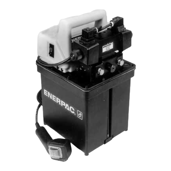
Instruction Sheet
1/2 hp Submerged Pumps
PEM/WEM PER/WER PEJ/WEJ PES/WES PED/WED
English .................................................... 1-8
Deutsch ................................................ 9-16
Polski .................................................. 17-24
Français ............................................. 25-32
WARNING: The system operating pressure must not
exceed the pressure rating of the lowest rated component
in the system. Install pressure gauges in the system to
monitor operating pressure. It is your window to what is
happening in the system.
gge.eps
CAUTION: Avoid damaging hydraulic hose. Avoid sharp
bends and kinks when routing hydraulic hoses. Using a
bent or kinked hose will cause severe back-pressure.
Sharp bends and kinks will internally damage the hose leading to
hosbnd.eps
premature hose failure.
Do not drop heavy objects on hose. A sharp impact
may cause internal damage to hose wire strands.
Applying pressure to a damaged hose may cause it to
rupture.
drag.eps
IMPORTANT: Do not lift hydraulic equipment by the
hoses or swivel couplers. Use the carrying handle or
other means of safe transport.
CAUTION: Keep hydraulic equipment away from
flames and heat. Excessive heat will soften packings
and seals, resulting in fluid leaks. Heat also weakens
hose materials and packings. For optimum performance do not
expose equipment to temperatures of 150°F [65°C] or higher.
Protect hoses and cylinders from weld spatter.
DANGER: Do not handle pressurized hoses. Escaping
oil under pressure can penetrate the skin, causing serious
injury. If oil is injected under the skin, see a doctor
immediately.
inject.eps
WARNING: Only use hydraulic cylinders in a coupled
system. Never use a cylinder with unconnected couplers.
If
the
cylinder
components can fail catastrophically causing severe personal
bdyhit.eps
injury.
WARNING: BE SURE SETUP IS STABLE BEFORE
LIFTING LOAD. Cylinders should be placed on a flat
surface that can support the load. Where applicable, use a
stblty.eps
becomes
extremely
overloaded,
Advertisement
Table of Contents

Related Manuals for Enerpac of 150


Summary of Contents for Enerpac of 150
- Page 1 L1498 Rev. E 07/21 English ............ 1-8 Repair Parts Sheets for this product are available from the Enerpac Deutsch ..........9-16 web site at www.enerpac.com, or from your nearest Authorized Polski ..........17-24 Enerpac Service Center or Enerpac Sales office.
-
Page 2: Specifications
For repair service, contact the Authorized ENERPAC Service Center in your area. To protect your warranty, use only ENERPAC oil. WARNING: Immediately replace worn or damaged parts by genuine ENERPAC parts. ø 4 Standard grade parts will break causing sman.eps... - Page 3 3.0 Description PER/WER Pump with electric solenoid valve and remote pendant. The submerged, 1/2 hp pump exists in five basic models. Each model is built with a common motor, cover plate and reservoir. The differences, between models, begins with variations in valves, pressure switches, heat exchangers and the combination of all the available options.
-
Page 4: Installation
4.0 INSTALLATION 4-Way Manual and Solenoid Valve Dump Valve Model 1. ON - OFF switch 1. ON - OFF switch 2. External relief valve 2. External relief valve 3. Gauge port 3. Gauge port 4. Mounting holes 4. Mounting holes 5. - Page 5 Install hydraulic hoses to valve (on pump) and cylinders. b. Control hydraulic Firmly tighten all couplers. fluid flow by moving valve handle to: CAUTION: Hand tighten couplers. Do not use tools. 1. ADVANCE Excessive force will cause damage which may lead to premature coupler failure.
- Page 6 Stainless steel plunger valve with self-locking a d j u s t m e n t adjusting thread section. Set point adjustment Advance ENERPAC Mounting bracket for installation of 3-way, 2-position valve shown. enclosed types in any position. Other valves are available.
-
Page 7: Maintenance
SPECIFICATIONS 5,000 psi Pump (WES Models) 10,000 psi Pump (PES Models) Pressure switch Model No. IC51 Pressure switch Model No. IC72 NEMA 1 Classification NEMA 12 Classification Pressure range: 3,000-5,000 psi Pressure range: 700-10,000 psi Maximum Differential: 350-800 psi Maximum Differential: 115-550 psi Electrical: 5 Amps at 125 VAC Electrical: 10 Amps at 125 VAC 250 VAC or 480 VAC... - Page 8 To drain oil, remove the fill plug. Tip the pump and drain oil out of fill opening. c. Re-fill reservoir with ENERPAC hydraulic oil. Use of any other oil or fluids could damage the pump, seals and hydraulic system components.
-
Page 9: Wichtige Sicherheitshinweise
1/2 hp Tauchpumpe PEM/WEM PER/WER PEJ/WEJ PES/WES PED/WED L1498 Rev. E 07/21 Das Ersatzteilblatt für dieses Produkt finden Sie auf der Enerpac Website www.enerpac.com, oder bei Ihrem nächstgelegenen authorisierten Enerpac Service Center oder einem Enerpac Vertriebsbüro. 1.0 WICHTIGE VERFAHRENSHINWEISE FÜR DEN EMPFANG: Alle Komponenten auf sichtbare Transportschäden inspizieren. - Page 10 Oberfläche aufsitzen, die fest genug ist, um die Hersteller versagen und verursachen Verletzungen und sman.eps Last abzustützen. Wenn möglich einen Zylinderfuß Sachschäden. ENERPAC-Teile werden so konstruiert, daß sie stblty.eps verwenden, um größere Stabilität zu gewährleisten. Keine richtig passen und hohen Lasten standhalten.
-
Page 11: Technische Daten
TECHNISCHE DATEN Modelle mit 350 bar Modelle mit 700 bar Strömung vs. Druck 2,47 l/min bei 0 – 70 bar 0,66 l/min bei 70 – 350 bar 0,33 l/min bei 70 – 700 bar Motorspannung B-Modelle – 115 V, 1-phasig, 50/60 Zyklus D-Modelle –... -
Page 12: Einbau
PED/WED Manuelles 4-Wege- und Magnetventil Basispumpe mit Druckablassventil (automatische Rückstellung). 1. EIN/AUS-Schalter Fernbedienung zur Steuerung des 2. Externes Überdruckventil Motors. 3. Manometeranschluss 4. Montagelöcher 5. Rücklaufanschluss 6. Vorlaufanschluss 4.0 EINBAU Modell mit Druckablassventil 1. EIN/AUS-Schalter Manometer werden zur Überwachung des Systemdrucks empfohlen. - Page 13 Hydraulikschläuche am Ventil (an der Pumpe) und an den b. Fluss der Hydraulik- Zylindern anbringen. Alle Kupplungen festziehen. flüssigkeit durch Bewegung des Griffs ACHTUNG: Kupplungen handfest anziehen. Keine in folgende Position Werkzeuge verwenden. Übermäßige Kraft verursacht steuern: Schäden, die zu einem vorzeitigen Kupplungsausfall 1.
- Page 14 15 A SPDT- Schalterausgang WES-Modelle = 350 bar Edelstahlkolben mit 3. Druckeinstellungen selbstsicherndem, einstellbarem Gewinde – siehe Schalter- und Sollwerteinstellung Ventileinstellung- sabschnitt Vorlauf ENERPAC 3-Wege-Ventil mit 2 Positionen Montagehalterung für den Einbau abgebildet. Andere Ventile sind geschlossener Typen in jeder Position. erhältlich.
-
Page 15: Wartung
TECHNISCHE DATEN 350-bar-Pumpen (WES-Modelle) 700-bar-Pumpen (PES-Modelle) Druckschalter Modell Nr. IC51 Druckschalter Modell Nr. IC72 NEMA 1-Klassifizierung NEMA 12-Klassifizierung Druckbereich: 210 – 300 bar Druckbereich: 420 - 700 bar Maximales Differential: 245 - 560 bar Maximales Differential: 60 - 385 bar Stromversorgung: 5 A bei 125 V Stromversorgung: 10 A bei 125 V 250 V oder 480 V... - Page 16 Öl ablassen und nach jeweils 300 Stunden Betrieb neues Öl einfüllen. b. Zum Ablassen des Öls, Füllstopfen entfernen. Pumpe kippen und Öl aus der Füllöffnung ablaufen lassen. c. Behälter wieder mit ENERPAC-Hydrauliköl füllen. Die Verwendung anderer Öle oder Flüssigkeiten kann die Pumpe, die Dichtungen und Hydrauliksystemkomponenten beschädigen.
-
Page 17: Ważne Informacje Dotyczące Bezpieczeństwa
W przypadku wątpliwości dotyczących zasad bezpieczeństwa OSTRZEŻENIE: Ciśnienie robocze układu nie może przekraczać ciśnienia danger.eps i procedur obsługi należy skontaktować się z firmą Enerpac. Jeżeli użytkownik nie odbył znamionowego komponentu układu o najniższej wartości znamionowej. Należy szkolenia z zasad bezpieczeństwa obowiązujących podczas pracy z wysokociśnieniowymi zainstalować... -
Page 18: Dane Techniczne
W sprawie napraw należy kontaktować się z lokalnym autoryzowanym centrum serwisowym firmy Enerpac. Aby zachować ważność gwarancji, należy używać tylko oleju firmy ENERPAC. OSTRZEŻENIE: Zużyte i uszkodzone części należy niezwłocznie wymienić na oryginalne części firmy ENERPAC. - Page 19 3.0 Opis PER/WER Pompa z zaworem elektromagnetycznym i kasetą zdalnego sterowania. Pompy zanurzeniowe o mocy 1/2 hp dostępne są w pięciu podstawowych modelach. Każdy model wyposażony jest w taki sam silnik, pokrywę i zbiornik. Modele różnią się zaworami, przełącznikami ciśnieniowymi, wymiennikami ciepła i różnymi kombinacjami wszystkich dostępnych opcji.
- Page 20 4.0 MONTAŻ 4-drogowy zawór ręczny i elektromagnetyczny Model z zaworem spustowym 1. Włącznik/wyłącznik 1. Włącznik/wyłącznik 2. Zewnętrzny zawór nadmiarowy 2. Zewnętrzny zawór nadmiarowy 3. Przyłącze manometru 3. Przyłącze manometru 4. Otwory montażowe 4. Otwory montażowe 5. Przyłącze powrotu 5. Przyłącze powrotu do zbiornika 6.
- Page 21 Zamocuj węże hydrauliczne do zaworu (na pompie) i cylindrów. Mocno dokręć b. Steruj przepływem płynu wszystkie złączki. hydraulicznego, przestawiając dźwignię zaworu na pozycję: PRZESTROGA: Złączki należy dokręcać ręcznie. Nie używaj narzędzi. Użycie 1. WYSUW zbyt dużej siły spowoduje uszkodzenie, które może doprowadzić do przedwczesnego zniszczenia złączki.
- Page 22 Wyjście przełącznika regulacji przełączników SPDT 15 A i zaworu. Tłok ze stali nierdzewnej z samohamownym gwintem regulującym Regulacja nastawy Wysuw Na rysunku pokazano zawór ENERPAC trójdrogowy, dwupozycyjny. Wspornik montażowy do instalacji modeli Dostępne są inne zawory. w obudowie w każdej pozycji.
- Page 23 DANE TECHNICZNE Pompa 350 bar (modele WES) Pompa 700 bar (modele PES) Przełącznik ciśnieniowy – nr modelu IC51 Przełącznik ciśnieniowy – nr modelu IC72 Klasyfikacja NEMA 1 Klasyfikacja NEMA 12 Zakres ciśnień: 210–350 bar Zakres ciśnień: 420–700 bar Maks. różnicowe: 245-560 bar Maks.
- Page 24 Spuść olej i napełnij zbiornik świeżym olejem po każdych 300 godzinach pracy. b. Aby spuścić olej, zdejmij korek wlewu. Przechyl pompę i spuść olej przez otwór wlewowy. c. Napełnij pompę olejem hydraulicznym firmy Enerpac. Użycie innego oleju lub innych płynów może spowodować uszkodzenie pompy, uszczelek i komponentów układu hydraulicznego.
- Page 25 élevé peut entraîner des dommages au niveau de l’équipement et/ ou d’un défaut d’entretien de l’équipement. En cas de doute concernant les ou des blessures. consignes de sécurité et les applications, n’hésitez pas à contacter Enerpac. Si danger.eps AVERTISSEMENT : la pression de service du système ne doit pas vous n’avez jamais suivi de formation sur la sécurité...
-
Page 26: Spécifications
IMPORTANT : l’entretien de l’équipement hydraulique doit uniquement être effectué par un technicien des systèmes hydrauliques qualifié et spécialisé. Pour toute réparation, contactez le centre d’entretien agréé Enerpac le plus proche. Utilisez exclusivement l’huile Enerpac afin de conserver votre garantie. AVERTISSEMENT : remplacez immédiatement les pièces ø... - Page 27 3.0 Description PER/WER Pompe avec électrovalve et télécommande. La pompe immergée de 1/2 HP est disponible en cinq modèles de base. Chaque modèle est équipé d’un moteur commun, d’un couvercle et d’un réservoir. Les différences entre les modèles incluent des variations au niveau des valves, des pressostats, des régulateurs thermiques et la combinaison de toutes les options disponibles.
- Page 28 4.0 INSTALLATION Électrovalve et valve manuelle à 4 voies Modèle avec valve de décharge 1. Commutateur Marche/Arrêt 1. Commutateur Marche/Arrêt 2. Soupape de sécurité externe 2. Soupape de sécurité externe 3. Orifice du manomètre 3. Orifice du manomètre 4. Orifices de fixation 4.
- Page 29 Installez les flexibles hydrauliques sur la valve (sur la pompe) et les b. Contrôlez le débit du vérins. Serrez fermement tous les raccords rapides. liquide hydraulique en déplaçant la manette de ATTENTION : serrez manuellement les raccords. N’utilisez pas la valve sur : d’outils.
- Page 30 Réglage de la valeur de commutateur et consigne de la valve. Avancée Une valve à 3 voies et 2 positions ENERPAC Support de fixation pour l’installation dans n’importe est ici représentée. D’autres valves quelle position des systèmes de type fermé. sont disponibles.
-
Page 31: Entretien
SPÉCIFICATIONS Pompe de 350 bars (modèles WES) Pompe de 700 bars (modèles PES) Nº du modèle du pressostat : IC51 Nº du modèle du pressostat : IC72 Classification NEMA 1 Classification NEMA 12 Plage de pressions : 210 - 300 bars Plage de pressions : 420 - 700 bars Pression différentielle max. : 245 - 560 bars Pression différentielle max. : 60 - 385 bars Circuit électrique : 5 A à... - Page 32 Remplissez à nouveau le réservoir avec de l’huile hydraulique Enerpac. L’utilisation de toute autre huile ou de tout autre liquide risque d’endommager la pompe, les joints et les composants du circuit hydraulique.
- Page 33 NOTES/NOTIZEN/UWAGI/NOTES:...
- Page 34 NOTES/NOTIZEN/UWAGI/NOTES:...
- Page 35 NOTES/NOTIZEN/UWAGI/NOTES:...
- Page 36 www.enerpac.com...
Need help?
Do you have a question about the of 150 and is the answer not in the manual?
Questions and answers