
Subscribe to Our Youtube Channel
Related Manuals for Miller Cool Runner 3CS


Summary of Contents for Miller Cool Runner 3CS
- Page 1 OM-230161G 2017-06 Processes TIG (GTAW) Welding MIG (GMAW) Welding Description Cool Runner 3CSt File: TIG (GTAW) For product information, Owner’s Manual translations, and more, visit www.MillerWelds.com...
- Page 2 We know you don’t have time to do it any other way. That’s why when Niels Miller first started building arc welders in 1929, he made sure his products offered long-lasting value and superior quality.
-
Page 3: Table Of Contents
TABLE OF CONTENTS SECTION 1 − SAFETY PRECAUTIONS - READ BEFORE USING ....... . . 1-1. -
Page 5: Section 1 − Safety Precautions - Read Before Using
SECTION 1 − SAFETY PRECAUTIONS - READ BEFORE USING coolers 2016-08 Protect yourself and others from injury — read, follow, and save these important safety precautions and operating instructions. 1-1. Symbol Usage DANGER! − Indicates a hazardous situation which, if Indicates special instructions. -
Page 6: California Proposition 65 Warnings
MOVING PARTS can injure. STEAM AND HOT COOLANT can burn. D Keep away from moving parts such as fans. Hose may rupture if coolant overheats. D Keep all doors, panels, covers, and guards D Visually inspect condition of hoses before each closed and securely in place. -
Page 7: Section 2 − Consignes De Sécurité − Lire Avant Utilisation
SECTION 2 − CONSIGNES DE SÉCURITÉ − LIRE AVANT UTILISATION Cooler 2016−08_fre Pour écarter les risques de blessure pour vous−même et pour autrui — lire, appliquer et ranger en lieu sûr ces consignes relatives aux précautions de sécurité et au mode opératoire. 2-1. -
Page 8: Proposition Californienne 65 Avertissements
LA VAPEUR ET LE LIQUIDE DE LIRE LES INSTRUCTIONS. REFROIDISSEMENT CHAUD peuvent provoquer des brûlures. D Lire et appliquer les instructions sur les étiquettes et Mode d’emploi avant Un tuyau peut se rompre lorsque le liquide de l’installation, l’utilisation ou l’entretien de refroidissement surchauffe. -
Page 9: Section 3 − Definitions
A complete Parts List is available at www.MillerWelds.com SECTION 3 − DEFINITIONS 3-1. Additional Safety Symbols And Definitions Some symbols are found only on CE products. Warning! Watch Out! There are possible hazards as shown by the symbols. Safe1 2012−05 Do not remove or paint over (cover) the label. -
Page 10: Miscellaneous Symbols And Definitions
A complete Parts List is available at www.MillerWelds.com 3-2. Miscellaneous Symbols And Definitions Some symbols are found only on CE products. Rated Maximum Line Connection Hertz Supply Current 1max Water (Coolant) Primary Voltage Input Power Output Degree Of Maximum Power Water (Coolant) Protection Consumption... -
Page 11: Section 4 − Specifications
SECTION 4 − SPECIFICATIONS 4-1. Serial Number And Rating Label Location The serial number and rating information for this product is located on the front. Use rating label to determine input power requirements and/or rated output. For future reference, write serial number in space provided on back cover of this manual. 4-2. -
Page 12: Section 5 − Installation
SECTION 5 − INSTALLATION 5-1. Selecting A Location Do not move or operate unit where it could tip. Loc_cooler 2016-08 Notes Work like a Pro! Pros weld and cut safely. Read the safety rules at the beginning of this manual. OM-230161 Page 8... -
Page 13: Installation
5-2. Installation Base Secure base to power source. Bottle Support Chain Secure bottle support to power source. Connect chain to bottle support. Universal Handle Secure handles to power source. Tools Needed: 3/8 in. 9/16 in. 805139-C OM-230161 Page 9... -
Page 14: Section 6 − Operation
SECTION 6 − OPERATION 6-1. Operation Coolant Tank Cap Coolant In Fitting Coolant Hose (Customer Supplied - Not Required On All Models) TIG Block Or International Style Water Adapter (Customer Supplied - Varies By Model) Connect coolant hose between Coolant In fit- ting and TIG block located on welding power source Electrode weld output terminal, or connect international style water adapter to... -
Page 15: Optional Cooler Connections
6-2. Optional Cooler Connections Disconnect cooler plug from welding power source re- ceptacle before filling. Remove cap and fill tank with three gallons of coolant (see Section 6). Gas Out Connection Connect TIG torch gas hose to gas out fitting. Electrode Weld Output Terminal TIG Block (Customer Sup-... -
Page 16: Section 7 − Maintenance & Troubleshooting
Unreadable Cracked Using Water) Labels Hoses 12 Months Change Coolant (If Using Miller Coolant) 7-2. Coolant Maintenance Disconnect cooler plug from welding power source receptacle before maintaining. Dispose of used coolant accord- ing to national, state, and local codes. Do not pour down drain. -
Page 17: Troubleshooting
7-3. Troubleshooting Trouble Remedy Coolant system does not work. Be sure input power cord is plugged into energized receptacle. Check line fuses or circuit breaker, and replace or reset if necessary. Motor overheated. Unit starts running when motor has cooled. Have Factory Authorized Service Agent check motor. -
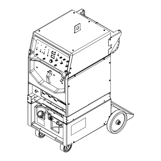
Page 18: Section 9 − Parts List
SECTION 9 − PARTS LIST Hardware is common and not available unless listed. 805100-D Figure 9-1. Running Gear For Cool Runner 3CS OM-230161 Page 14... - Page 19 Dia. Part Mkgs. Description Quantity Figure 9-1. Running Gear For Cool Runner 3CS Cooler ... . +215928 Bottle Support ............
- Page 20 Hardware is common and not available unless listed. 804995-A Figure 9-2. Cooling Unit Main Assembly OM-230161 Page 16...
- Page 21 Item Part Description Quantity Figure 9-2. Cooling Unit Main Assembly ... . . 213072 Fan, Muffin 115 V 60 Hz 3400 Rpm 6.378 Mtg Holes ....
- Page 22 Notes OM-230161 Page18...
- Page 23 Effective January 1, 2017 (Equipment with a serial number preface of MH or newer) This limited warranty supersedes all previous Miller warranties and is exclusive with no other guarantees or warranties expressed or implied. Warranty Questions? LIMITED WARRANTY − Subject to the terms and conditions below, 6 Months —...
- Page 24 Contact the Delivering Carrier to: File a claim for loss or damage during shipment. For assistance in filing or settling claims, contact your distributor and/or equipment manufacturer’s Transportation Department. © ORIGINAL INSTRUCTIONS − PRINTED IN USA 2017 Miller Electric Mfg. Co. 2017−01...
Need help?
Do you have a question about the Cool Runner 3CS and is the answer not in the manual?
Questions and answers