Speco VM-1201B Service Manual
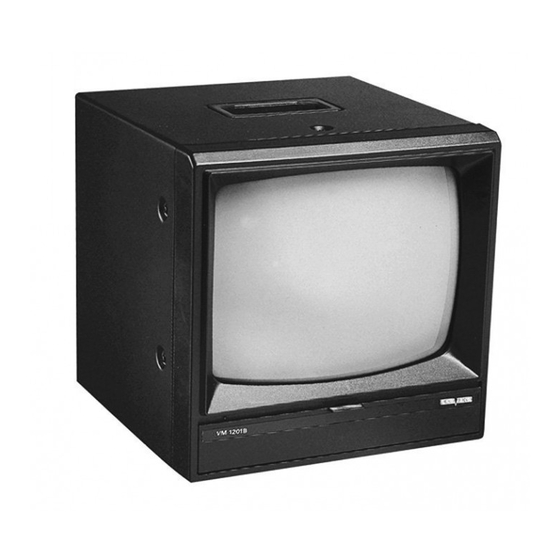
High performance monochrome monitor
Hide thumbs
Also See for VM-1201B:
- Specification sheet (1 page) ,
- Instruction manual (12 pages) ,
- Instruction manual (12 pages)
Table of Contents
Advertisement
Quick Links
Download this manual
See also:
Instruction Manual
Advertisement
Table of Contents

Related Manuals for Speco VM-1201B


Summary of Contents for Speco VM-1201B
- Page 1 SERVICE MANUAL MODEL REVISION DATE DOCUMENT NUMBER : : VM-1201 : : MAY. 21. 2001...
-
Page 2: Table Of Contents
Furthermore Speco Technologies reserves the right to revise this publication and to make changes from time to time in contents hereof without obligation to notify any person of such revision or changes. - Page 3 2.4 VERTICAL DEFLECTION BLOCK...……………………..………... 2.5 HORIZONTAL DEFLECTION BLOCK...……………………...……... 3. TROUBLESHOOTING INSTRUCTIONS...……………...…….….. 3.1 NO DISPLAY, NO POWER...…………………………………………………….. 3.2 NO DISPLAY, (POWER OK)...………………………………………………………….. 3.3 NO DISPLAY, (NO ASTER) ……………………………………………...…………….. 3.4 NO PICTURE OR NO COLOR (RASTERK)...………………………...…………. 3.5 VERTICAL DEFLECTION FAILURE...…………………..……….. APPENDIX: A. SPARE PARTS LIST B.
-
Page 4: Introduction
This service manual is primarily for system / service engineers, distributors and dealers. It carries the assumption that the reader understands the basic operating concepts. Purpose This manual contains reference data for Speco Technologies monitor. It gives information regarding the operating principles of monitors, as well as technical service and maintenance information. 1. Introduction The VM-1201, high performance monochrome monitor, display over 1,000 TV lines resolution on a bright 12-inch picture tube. -
Page 5: Signal Input Requirements
1.1.2 Signal Input Requirements ‧ Connector For CVBS:BNC terminal Type:composite video input Synchronous:0.3 V Luminance:0.7V Polarity:Positive bright Impedance:75 ohms 1.1.3 Power Input Requirements ‧ Operating Voltage Range:90 ~ 264 V ‧ Input Current at 90 V Operating:0.5 Amps rms. maximum ‧... -
Page 6: Display Quality
:25 ±5℃ • Temperature :No additional magnetic field in near side • Magnetic field :100 ~ 240 V • AC line Input :30 minutes min. after power on and signal applied • Warm-up Time :400 to 600 lux. • Ambient light 1.2.1 Display Quality ‧... -
Page 7: Control And Adjustments
‧ Picture geometry:≦ 2.5% ‧ Picture centering:≦ 6mm ‧ Size stability:Picture luminance from 5 FL to max., the size shall be less than 2.5% ‧ Swing and jitters:Swing and jitters are not allowed (viewed at 50cm from eyes to ‧ Focus:(viewed at 50cm from eye to screen, contrast adjusted to set luminance at 20 FL with full white pattern, brightness set at raster just disappeared) Inspect full character pattern, all characters should be distinguished. -
Page 8: Main Power Supply Block
This section describes each functional block of the monitor. 2.1 Main Power Supply Block • AC power input:AC socket • Line input noise / EMI filtering:Line filter T902 ; • Over current protection:Fuse • Power on/off control:Power switch • AC to DC conversion and filtering:Diode D901, Capacitor C906 •... -
Page 9: Video Input Block
• Snubber circuit:Snubber C907, D902, R902. • Primary side self-powering circuit:D903,C914. • Output 13.5 volts for vertical & horizontal drive circuits:D904, C915. • Output 27.5volts for horizontal deflection circuit:D906 ,C916. 2.2 Video input block • Signal input buffering and switch ‧... -
Page 10: Phase Detector
black level is stored at pin7 by C404. The slicing level is stored at pin6 by C403 and decided by R403. 2.3.4 Phase detector: The phase detector circuit is connected to pin8. The circuits are activated depending on the voltage of pin18 and the state of the Sync pulse noise detection circuit, C405, C406, R405. -
Page 11: Horizontal Deflection Block
• Flyback generator: ‧ U301 pin6 is the output of the flyback generator that when driven, jumps from low to high condition C305 transfers the jump to pin3 • Vertical size control:VR301, R312, R308. 2.5 Horizontal Deflection Block • Horizontal drive buffering:Driving source-U401 pin11. Driving transistor-Q40, to pull high the •... -
Page 12: No Display, (Power Ok)
3.1.5 If driving pulses at U901 pin6 and drain of Q901 are correct but voltage at U901 pin 7 low than threshold voltage --causing U901 to stop and restart periodically, check and repair following circuits. Power transformer T901 bad; D903 short-circuit/opened. 3.2 No Display, power output normal. -
Page 13: Appendix A. Spare Parts List
Appendix A. Spare Parts List Location F901 D901 D902 D501, D502 D903, D904, D301 D906, D401 Q901 Q201, Q202, Q206, Q402, Q501 Q205 Q502 Q203, Q204 U401 U301 U901 T401 T901 R902 R904 R614 Parts Number 28-1100-0006 06-3100-0005 06-1100-0001 06-1100-0023 06-1100-0014 06-1100-0058 08-3100-0011... -
Page 14: Appendix B. Schematics And Pcb Layout Diagram
Appendix B. Schematics and PCB Layout Diagram 1. Schematics Page 1 -- Main Board, Video Board. 2. Schematics Page 2 – Power Supply, Video Amplifier 3. PCB Layout -- Video Board, Circuit Trace 4. PCB Layout -- Main Board, Silk Screen... - Page 15 Rt/Ct Vref...
- Page 16 2SC1815 Q203 2.2U/50V C205 C410 .15 C204 10U/16V R211 3.3K R209 120 R306...
Need help?
Do you have a question about the VM-1201B and is the answer not in the manual?
Questions and answers