Table of Contents
Advertisement
Quick Links
5 7 5 J * 0 7 - 1 2
Heat Pump Condensing Units
with P ur on
®
Refrigerant
Installation, Start-Up and Service Instructions
CONTENTS
SAFETY CONSIDERATIONS . . . . . . . . . . . . . . . . . . . . . . 2
GENERAL . . . . . . . . . . . . . . . . . . . . . . . . . . . . . . . . . . . . . . . 2
Rated Indoor Airflow (cfm) . . . . . . . . . . . . . . . . . . . . . . . . . 2
INSTALLATION GUIDELINE . . . . . . . . . . . . . . . . . . . . . 2
Replacement /Retrofit - R-22 to Puron Refrigerant . . . . . . 2
INSTALLATION . . . . . . . . . . . . . . . . . . . . . . . . . . . . . . . . . 8
Jobsite Survey . . . . . . . . . . . . . . . . . . . . . . . . . . . . . . . . . . . . 8
Step 1 - Plan for Unit Location . . . . . . . . . . . . . . . . . . . . . 8
Step 2 - Complete Pre-Installation Checks . . . . . . . . . . . 8
Step 3 - Prepare Unit Mounting Support . . . . . . . . . . . . . 8
Step 4 - Rig and Mount the Unit . . . . . . . . . . . . . . . . . . . . 8
Check Vertical Separation . . . . . . . . . . . . . . . . . . . . . . . . . 10
Provide Safety Relief . . . . . . . . . . . . . . . . . . . . . . . . . . . . . 10
Refrigerant Line Sizing . . . . . . . . . . . . . . . . . . . . . . . . . . . 10
Risers in Heat Pump Piping Systems . . . . . . . . . . . . . . . . 10
Install Filter Drier and Moisture Indicator . . . . . . . . . . . 10
Install Liquid Line Solenoid Valves . . . . . . . . . . . . . . . . . 11
Make Piping Connections . . . . . . . . . . . . . . . . . . . . . . . . . 11
Evacuation/Dehydration . . . . . . . . . . . . . . . . . . . . . . . . . . 12
Preliminary Charge . . . . . . . . . . . . . . . . . . . . . . . . . . . . . . 12
Step 6 - Install Accessories . . . . . . . . . . . . . . . . . . . . . . . 12
Step 7 - Complete Electrical Connections . . . . . . . . . . . 12
Convenience Outlets . . . . . . . . . . . . . . . . . . . . . . . . . . . . . . 13
Installing Weatherproof Cover . . . . . . . . . . . . . . . . . . . . . 14
Step 8 - Wind Baffles for Low Ambient Control . . . . . . 17
PRE-START-UP . . . . . . . . . . . . . . . . . . . . . . . . . . . . . . . . . 17
System Check . . . . . . . . . . . . . . . . . . . . . . . . . . . . . . . . . . . 17
Turn On Crankcase Heater . . . . . . . . . . . . . . . . . . . . . . . . 17
Preliminary Charge . . . . . . . . . . . . . . . . . . . . . . . . . . . . . . 17
START-UP . . . . . . . . . . . . . . . . . . . . . . . . . . . . . . . . . . . . . 17
Manufacturer reserves the right to discontinue, or change at any time, specifications or designs without notice and without incurring obligations.
Catalog No. 04-53575003-01
Page
Printed in U.S.A.
Form No. II575J-7-12-04
575J Units . . . . . . . . . . . . . . . . . . . . . . . . . . . . . . . . . . . . . . 17
OPERATING SEQUENCE . . . . . . . . . . . . . . . . . . . . . . . . 21
Base Unit Controls . . . . . . . . . . . . . . . . . . . . . . . . . . . . . . . 21
ROUTINE SYSTEM MAINTENANCE . . . . . . . . . . . . . 23
(and 30 days after initial start) . . . . . . . . . . . . . . . . . . . 23
MAINTENANCE . . . . . . . . . . . . . . . . . . . . . . . . . . . . . . . . 23
Quarterly Inspection
(and 30 days after initial start) . . . . . . . . . . . . . . . . . . . 23
• INDOOR SECTION
Seasonal Maintenance . . . . . . . . . . . . . . . . . . . . . . . . . . . . 23
SERVICE . . . . . . . . . . . . . . . . . . . . . . . . . . . . . . . . . . . . . . 24
Refrigeration System . . . . . . . . . . . . . . . . . . . . . . . . . . . . . 24
Compressor Protection . . . . . . . . . . . . . . . . . . . . . . . . . . . 27
Commercial Defrost Control . . . . . . . . . . . . . . . . . . . . . . . 27
Pg 1
2-23
Replaces: II575J-7-12-03
Advertisement
Table of Contents

Related Manuals for Carrier Bryant 575J 07 Series


Summary of Contents for Carrier Bryant 575J 07 Series
-
Page 1: Table Of Contents
5 7 5 J * 0 7 - 1 2 Heat Pump Condensing Units with P ur on ® Refrigerant Installation, Start-Up and Service Instructions CONTENTS 575J Units ........17 •... -
Page 2: Safety Considerations
COMFORT ALERT DIAGNOSTIC MODULE ..31 WARNING Outdoor Fans ........33 Lubrication . -
Page 3: Evaluate Existing Refrigerant Piping
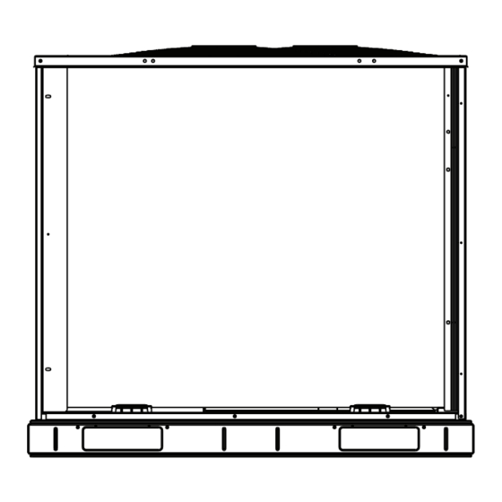
this system in COOLING ONLY. Remove the suction line filter Drain oil from low points and traps in vapor line tubing if drier as soon as possible, with a maximum of 72 hours of they were not replaced. operation. Remove the existing outdoor unit. Install the new outdoor Recommendation: Install a ball valve in the liquid line at the unit according to these installation instructions. - Page 4 Fig. 1 — 575J*07-12 Unit Dimensions...
- Page 5 Table 2 — 575J Corner Weights STD. UNIT CORNER A CORNER B CORNER C CORNER D CENTER OF GRAVITY UNIT HEIGHT UNIT 575J*07 22 (558.8) 25 (635.0) 13 (330.2) 42-3/8 (1076.0) 575J*08 21 (533.4) 24 (609.6) 23 (584.2) 50-3/8 (1279.2) 575J*12 21 (533.4) 24 (609.6)
- Page 6 Table 4 — Physical Data — 575J*07-12 Units — 60 Hz SI UNIT 575J*07G/H 575J*08M/N 575J*12G/H Nominal Capacity (kW) 21.1 26.4 35.1 Operating Weights (kg) Aluminum-Fin Coils Refrigeration System R-410A R-410A R-410A No. Circuits / No. Comp. / Type 1 / 1 / Scroll 1 / 1 / Scroll 1 / 1 / Scroll Shipping Charge A/B (kg)
- Page 7 10 11 12 13 14 15 16 17 J E 0 7 G 0 0 A 0 0 A 0 A Model Type Packaging 575J = Bryant Condensing Unit A = Standard ® Puron R-410A Refrigerant B = LTL Voltage Base Unit Controls E = 460/3/60 0 = Electro-Mechanical Controls...
-
Page 8: Installation
INSTALLATION INSPECT SHIPMENT File a claim with shipping company if the shipment is damaged Jobsite Survey or incomplete. Complete the following checks before installation. CONSIDER SYSTEM REQUIREMENTS Consult local building codes and the NEC (National Electri- Code) ANSI/NFPA 70 special installation •... - Page 9 Table 5 — 575J*07-12 Piping Recommendations (Single-Circuit Unit) R-410A EQUIVALENT LENGTH (ft) Length Linear 0-24 25-49 50-74 75-100 Model Nominal Capacity Length Equiv 0-37 38-74 75-112 113-150 Liquid Line (in.) Max Lift Cool 575J*07G/H Max Lift Heat Suction Line (in.) 1-1/8 1-1/8 Charge (lb)
-
Page 10: Check Vertical Separation
Check Vertical Separation Table 6 — Maximum Vapor Line Sizes If there is any vertical separation between the indoor and out- 575J UNIT 575J UNIT door units, check to ensure that the separation is within allow- BELOW ID UNIT ABOVE ID UNIT 575J* UNIT able limits. -
Page 11: Install Liquid Line Solenoid Valves
Install Liquid Line Solenoid Valves Make Piping Connections It is recommended that a bi-directional solenoid valve be Piping connections at the 575J unit are ball valves with stub placed in the main liquid line (see Fig. 5 and 6) between the tube extensions. -
Page 12: Evacuation/Dehydration
Evacuation/Dehydration Table 10 — Minimum Outdoor Air Operating Temperature Evacuate and dehydrate the connected refrigeration system(s) (excluding the 575J unit) to 500 microns using a two-stage MINIMUM OUTDOOR vacuum pump attached to the service ports outside the 575J PERCENT TEMP, °F (°C) service valves, following description in GTAC II, Module 4, UNIT COMPRESSOR... -
Page 13: Units Without Factory-Installed Disconnect
connected to a 208-v power supply, the control transformer must be rewired by moving the black wire with the 1/4 in. fe- male spade connector from the 230-v connection and moving it to the 208-v 1/4 in. male terminal on the primary side of the Electric transformer. -
Page 14: Installing Weatherproof Cover
on a bracket behind the convenience outlet; access is through Installing Weatherproof Cover the unit’s control box access panel. See Fig. 10. A weatherproof while-in-use cover for the factory installed The primary leads to the convenience outlet transformer are convenience outlets is now required by UL standards. This not factory-connected. -
Page 15: External Control Devices
575J unit control system requires a conventional electric ther- THERMOSTAT mostat that will energize the G terminal on a call for Cool and OUTDOOR UNIT Heat mode. Do not configure the thermostat a heat pump type; CONNECTION BOARD (TB) Heat mode will not work with a thermostat configured for heat pump. - Page 16 Table 11 — Electrical Data — 575J*07-12 60 Hz Units NOMINAL COMPRESSOR WITHOUT POWERED CONVENIENCE OUTLET VOLTAGE POWER RANGE No. 1 No. 2 OFM (ea) Power Supply Disconnect Size SUPPLY UNIT Fuse or V-Ph-Hz HACR Brkr 208/230-3-60 17.5 — — 25/25 30/30 24/24...
-
Page 17: Step 8 - Wind Baffles For Low Ambient Control
Step 8 — Wind Baffles for Low Ambient Control CAUTION 575J***H and 575J***N units includes the factory installed low ambient controller. UNIT DAMAGE HAZARD Units with low ambient control require the addition of wind Failure to follow this caution may result in equipment dam- baffles to ensure full range low ambient operation. -
Page 18: Advanced Scroll Temperature Protection (Astp)
ADVANCED SCROLL TEMPERATURE PROTECTION To manually reset ASTP, the compressor should be stopped and allowed to cool. If the compressor is not stopped, the mo- (ASTP) tor will run until the motor protector trips, which occurs up to A label located above the terminal box identifies Copeland ™1 90 minutes later. - Page 19 6 TON HEAT PUMP DUAL STAGE CHARGING CHART R-410A (COMPRESSOR FULL LOAD, ALL CONDENSER FANS OPERATING) Add Charge if Above the Curve Rem ove Charge if Below the Curve –6 1050 1400 1750 2100 2450 2800 3150 3500 3850 Pressure at Liquid Valve (PSIG / Kpa) PN: 38AU000485 REV - Fig.
- Page 20 7.5 Ton Dual Stage Heat Pump Charging Chart R-410A Refrigerant Add Charge if Above the Curve Rem ove Charge if Below the Curve –6 1050 1400 1750 2100 2450 2800 3150 3500 3850 Pressure at Liquid Valve (PSIG / Kpa) 38AU000063 Fig.
-
Page 21: Operating Sequence
10 Ton Heat Pump Dual Stage Charging Chart R-410A (compressor full load, all condenser fans operating) PN: 38AU000486 REV - Fig. 18 — 575J*12G/H Charging Chart OPERATING SEQUENCE 575J*12G/H uses two compressors in tandem on a single cir- cuit in conjunction with two single-stage Comfort Alert Mod- Base Unit Controls ules (CADM). -
Page 22: Fan Cycling
When thermostat calls for Stage 2 Cooling, terminal Y2 is motor sensors); CADM relay opens and RED LED is illumi- energized. The 575J unit’s Defrost Board (DFB) receives this nated. TRIP condition maintains lockout of compressor input at P2-4. DFB issues 24-v outputs at OF, P3-8 (COMP2). operation until CADM is manually reset. -
Page 23: Supplemental Heat/Emergency Heat
hot gas into the outdoor coil where its heat melts the frost and MAINTENANCE loosens the ice on the coil face. These items should be part of a routine maintenance program, During the Defrost cycle, output EHEAT is also energized (if to be checked every month or two, until a specific schedule for not already energized by a thermostat W2 demand);... -
Page 24: Service
SERVICING SYSTEMS ROOFS WITH Table 13 — Indoor Unit Maintenance Checklist SYNTHETIC MATERIALS RECOMMENDED MAINTENANCE CHECKLIST POE (polyolester) compressor lubricants are known to cause INTERVAL long term damage to some synthetic roofing materials. Expo- Outdoor unit specific: (for accessories Monthly Annual sure, even if immediately cleaned up, may cause embrittlement refer to unit specific literature) -
Page 25: Outdoor Coil Metering Devices
Outdoor Fan 2 Outdoor Fan 2 Outdoor Fan 1 Outdoor Fan 1 Service Valves Service Fig. 19 — 575J*07G/H Exterior Valves Fig. 21 — 575J*12G/H Exterior Outdoor Fan 2 OUTDOOR COIL METERING DEVICES Outdoor Fan 1 The metering devices are multiple fixed-bore devices (Acutrol ™1 ) swaged into the horizontal outlet tubes from the... - Page 26 Outdoor Coil Outdoor Coil Defrost Defrost Thermostat Thermostat (DFT) (DFT) High Flow Access Ports Fig. 22 — 575J*07G/H Interior High Flow Access Ports Fig. 24 — 575J*12G/H Interior Outdoor Coil Defrost Thermostat (DFT) Defrost Thermostat (DFT) High Flow Access Ports Fig.
-
Page 27: Compressor Protection
The crankcase heater will operate as long as the power circuit Seat is energized. The main disconnect must be on to energize the crankcase heater. 1/2-20 UNF RH IMPORTANT: Never open any switch or disconnect that 0.596 energizes the crankcase heater unless unit is being serviced or is to be shut down for a prolonged period. - Page 28 Table 14 — 575J Defrost Board I/O and Jumper Configurations CONNECTION PIN POINT NAMES TYPE OF I/O UNIT CONNECTION NOTE NUMBER INPUTS G Fan DI, 24-vac P2-3 Not used Y1 Cool 1 DI, 24-vac P2-5 TB-Y1 W1 Heat 1 DI, 24-vac P2-7 TB-W1 Y2 Cool 2...
-
Page 29: Reversing Valve Control
At the end of the continuous run period, the defrost control will test for a need to defrost. DFT1 controls the start and termina- tion of the defrost cycle. If DFT1 is still open, the defrost test/run window is closed and the control repeats the continu- ous run period. - Page 30 Table 16 — Dip Switch Position SWITCH NO. • • • • • • • • • 30 minutes 60 minutes 90 minutes 120 minutes Delay For size 08 units, position the DFT on the Vapor Stub For size 12 units, (second from top) position the DFT For size 07 units,...
- Page 31 COMFORT ALERT DIAGNOSTIC MODULE Power The Comfort Alert Diagnostic Module (CADM) monitors and (GRN) Comfort Alert ™ analyzes data from the Copeland Scroll ® three-phase compres- Commercial Diagnostics POWER sor and the thermostat demand. The CADM also provides a Green LED - 24VAC Power Yellow LED - Flash Code System Pressure Trip 3-minute anti-recycle time delay to compressor cycling.
- Page 32 Table 17 — LED Status Codes STATUS LED STATUS LED STATUS LED DESCRIPTION TROUBLESHOOTING INFORMATION Green “POWER” Module has power Supply voltage is present at module terminals 1. Compressor protector is open 2. Condensing unit power disconnect is open Thermostat demand signal Y is present, but 3.
- Page 33 Table 18 — CADM Troubleshooting MISWIRED MODULE INDICATION RECOMMENDED TROUBLESHOOTING ACTION Determine if both R and C module terminals are connected. Verify voltage in present at module’s R and C terminals. NOTE: The CADM requires a constant nominal 24VAC power supply. The wiring to the Green LED is not on, module does not power up module’s R and C terminals must be directly from the control transformer.
- Page 34 Avoid the use of: • coil brighteners • acid cleaning prior to painting Rigid • high pressure washers Support • poor quality water for cleaning Cover Totaline environmentally sound coil cleaner is nonflammable, hypoallergenic, non bacterial, and a USDA accepted biode- gradable agent that will not harm the coil or surrounding com- ponents such as electrical wiring, painted metal surfaces, or in- sulation.
- Page 35 Service Parts FASTENER TORQUE VALUES Listings of service parts for all units are available from the Re- placement Components Division’s Electronic Parts Informa- 65-75 in.-lb Compressor mounting bolts tion Catalog (EPIC). EPIC is available at Totaline stores, dis- (734-847 N-cm) tributor and service office parts departments and online at 20 ±2 in.-lb Condenser fan motor mounting bolts...
- Page 36 TROUBLESHOOTING PROBLEM CAUSE REMEDY Power failure. Call power company. Replace fuse or reset circuit breaker. Determine root Fuse blown or circuit breaker tripped. cause. Defective thermostat, contactor, transformer, control Replace component. relay, or capacitor. Insufficient line voltage. Determine cause and correct. Incorrect or faulty wiring.
- Page 37 APPENDIX A — AIR CONDITIONER AND HEAT PUMP WITH PURON ® — QUICK REFERENCE GUIDE • Puron (R-410A) refrigerant operates at 50 percent to • POE oils may cause damage to certain plastics and roofing 70 percent higher pressures than R-22. Be sure that servic- materials.
- Page 38 APPENDIX B — WIRING DIAGRAM LIST (CONT) Fig. A — 575J*07G/H Single Circuit / Two Stage Wiring Diagram (208/230, 460-3-60 shown)
- Page 39 APPENDIX B — WIRING DIAGRAM LIST (CONT) Fig. B — 575J*07G/H Single Circuit / Two Stage Wiring Diagram (575-3-60 shown)
- Page 40 APPENDIX B — WIRING DIAGRAM LIST (CONT) Fig. C — 575J*08M/N Single Circuit / Two Stage Wiring Diagram (208/230-3-60 shown)
- Page 41 APPENDIX B — WIRING DIAGRAM LIST (CONT) Fig. D — 575J*08M/N Single Circuit / Two Stage Wiring Diagram (460-3-60 shown)
- Page 42 APPENDIX B — WIRING DIAGRAM LIST (CONT) Fig. E — 575J*08M/N Single Circuit / Two Stage Wiring Diagram (575-3-60 shown)
- Page 43 APPENDIX B — WIRING DIAGRAM LIST (CONT) Fig. F — 575J*12G/H Single Circuit / Two Stage Wiring Diagram (208/230, 460-3-60 shown)
- Page 44 APPENDIX B — WIRING DIAGRAM LIST (CONT) Fig. G — 575J*12G/H Single Circuit / Two Stage Wiring Diagram (575-3-60 shown)
- Page 45 APPENDIX C — LOW AMBIENT OPTION — FACTORY INSTALLED Units with the factory installed low ambient option are TROUBLESHOOTING equipped with a solid-state head pressure control which regu- lates fan speed. A temperature sensor, mounted on circuit 1 of OBSERVATION POSSIBLE REMEDY the outdoor coil (see Fig.
- Page 46 APPENDIX C — LOW AMBIENT OPTION — FACTORY INSTALLED (CONT) Low ambient sensor must be positioned Low ambient sensor on vapor stub Low ambient sensor must be positioned (fourth from top) must be positioned on vapor stub between (fourth from top) metering device (second from top) and tube sheet...
- Page 47 APPENDIX C — LOW AMBIENT OPTION — FACTORY INSTALLED (CONT) Fig. I — Wind Baffles...
- Page 50 Printed in U.S.A. Form No. II575J-7-12-04 © 2023 Carrier Cat. No. 04-53575003-01 Edition Date: 2-23 Manufacturer reserves the right to change, at any time, specifications and designs without notice and without obligations. Replaces: II575J-7-12-03...
- Page 51 START-UP CHECKLIST FOR 575J*07-12 HEAT PUMP CONDENSING UNIT (Remove and use for job file) NOTE: To avoid injury to personnel and damage to equipment or property when completing the procedures listed in this start-up checklist, use good judgment, follow safe practices, and adhere to the safety considerations/information as outlined in preceding sections of this Installation, Start-Up and Service Instruction document.
- Page 52 _______________________________________________________________________________________________________ _______________________________________________________________________________________________________ _______________________________________________________________________________________________________ _______________________________________________________________________________________________________ _______________________________________________________________________________________________________ Printed in U.S.A. Form No. II575J-7-12-04 © 2023 Carrier Cat. No. 04-53575003-01 Edition Date: 2-23 Manufacturer reserves the right to change, at any time, specifications and designs without notice and without obligations. CL-2 Replaces: II575J-7-12-03...
Need help?
Do you have a question about the Bryant 575J 07 Series and is the answer not in the manual?
Questions and answers