Table of Contents
Advertisement
Quick Links
Advertisement
Table of Contents

Subscribe to Our Youtube Channel
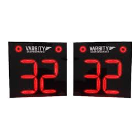
Summary of Contents for VARSITY Scoreboards 2210
- Page 1 MODEL 2210 Installation Manual...
- Page 2 MODEL 2210 INSTALLATION WARRANTY This product is warranted against defects in materials and workmanship for the period specified in the warranty from the date of invoice. SERVICE Technical Support is available 24 hours a day, 7 days a week. 1-800-411-3136 https://www.varsityscoreboards.com/support/contact-support.html...
- Page 3 A NOTE TO INSTALLERS If you are installing these shot clocks for a client, please return the manual to the individual in charge of the shot clocks upon completion of installation. SHOT CLOCK DIMENSIONS 26” wide x 25” tall x 6” depth...
-
Page 4: Table Of Contents
TABLE OF CONTENTS MODEL 2210 INSTALLATION INSTALLATION OVERVIEW PRODUCT SPECIFICATIONS MOUNTING THE SHOT CLOCKS TO A WALL SUSPENDING THE SHOT CLOCKS CONNECTING AND RUNNING ELECTRIC WIRELESS SHOT CLOCKS BBL CONNECTION TESTING THE INSTALLED SYSTEM... -
Page 5: Model 2210 Installation
MODEL 2210 INSTALLATION Please inspect all shipping containers upon arrival for damage and ensure that you have all of the parts listed below: ITEMS IN LARGE PACKAGE(S) (2) 26” x 25” Basketball Shot Clocks Shipped in two (2) sections... - Page 6 Ask the delivery driver to call the local terminal and report immediately. Contact Varsity Scoreboards immediately while the delivery driver is still present to report the damage A. Phone number B.
-
Page 7: Installation Overview
INSTALLATION OVERVIEW This manual will walk you through the installation of the shot clocks. While care has been taken to consider the many scenarios for installation, some general information applies to all. Follow this guide as closely as possible to ensure proper installation. Review the product specifications below to determine your specific installation hardware. -
Page 8: Product Specifications
PRODUCT SPECIFICATIONS OVERALL DIMENSIONS WEIGHT 26” L x 25” W x 6” D - shipped in two (2) Hanging weight = approximately 35 lbs per clock sections Shipping weight = approximately 100 lbs CONSTRUCTION 22-gauge galvanneal steel cabinet with powder coat finish for strength, durability, and lasting appearance INSTALLATION RECOMMENDATIONS We recommend this model to be installed by mounting to a wall or... -
Page 9: Mounting The Shot Clocks To A Wall
MOUNTING THE SHOT CLOCKS ON A WALL Carefully remove each shot clock from its packaging, making sure not to pry against or cut into the clock’s cabinet. Inspect each unit for shipping damage according to the instructions on page 6. Connect a lift device to the hanging/lifting holes on the top of the clock and lift the unit into place. -
Page 10: Suspending The Shot Clocks
SUSPENDING THE SHOT CLOCKS Carefully remove each shot clock from its packaging, making sure not to pry against or cut into the clock’s cabinet. Inspect each unit for shipping damage according to the instructions on page 6. If the clock must be lifted into place before the permanent sus- pension cables can be attached the unit may be raised into posi- tion by connecting a lift device to the two top mounting holes in the unit’s left and right mounting flanges. -
Page 11: Connecting And Running Electric
RUNNING & CONNECTING THE ELECTRIC SERVICE NOTE: THIS PORTION OF THE INSTALLATION REQUIRES A LICENSED ELECTRICIAN. IDEALLY, THE SCOREBOARAD WILL BE POWERED FROM A DEDICATED 120V/20A CIRCUIT. ADDITIONALLY, SINCE THE SCOREBOARD’S POWER SHOULD BE TURNED OFF AFTER EACH USE, THERE SHOULD BE EASY ACCESS TO THE POWER SWITCH OR CIRCUIT BREAKER. -
Page 12: Wireless Shot Clocks
WIRELESS SHOT CLOCKS Below is a picture of the back of one of the wireless shot clocks. The wireless receiver is attached inside the unit and you have up to 10 feet of slack on its cable. Remotely mount this receiver by removing the white strips off the adhesive and place on a clean, smooth, surface in close proximity to the shot clock. -
Page 13: Bbl Connection
BBL CONNECTION The Backboard Lighting (BBL) connection point is on the top of each of the shot clocks. Once the shot clocks are installed and the BBL strips are installed, plus the XLR connection to a port as shown below. Please refer to your BBL Installation Manual for further instructions on their installation. -
Page 14: Testing The Installed System
INSTALLING THE HAND-HELD CONTROLLER Connect the RS-232 jack to the port on the back of the LCD controller. See image below. RS-232 Jack TESTING THE INSTALLED SYSTEM AFTER INSTALLATION IS COMPLETE, HAVE THE INSTALLER TEST THE SHOT CLOCKS BY FOLLOWING THE STEPS BELOW: While holding down the The screen will display The screen will display... - Page 15 Congratulations! You’ve successfully installed your Varsity Scoreboard Shot Clocks! If any problems arise, please have the installer call Varsity Scoreboards Customer Service at 800-411-3136 while the installer is still present at the install location.


Need help?
Do you have a question about the 2210 and is the answer not in the manual?
Questions and answers