
Related Manuals for All American Scoreboards MP-5203


Summary of Contents for All American Scoreboards MP-5203
- Page 1 OPERATING INSTRUCTIONS AND SERVICE MANUAL BASKETBALL SCOREBOARD MODEL MP-5203 EFFECTIVE S.N. 17,100, March, 2001...
-
Page 2: Table Of Contents
TABLE OF CONTENTS GENERAL INFORMATION DESCRIPTION IDENTIFICATION DAMAGE DAMAGE CLAIM PROCEDURE INSTALLATION GENERAL INFORMATION INSPECTION PRE-TEST ELECTRICAL CONNECTIONS CONTROL CONSOLE OPERATION SCOREBOARD POWER CONSOLE DISPLAY CONSOLE POWER TO USE SCOREBOARD TIME SETTING AND CONTROL HORN MAINTENANCE AND TROUBLESHOOTING INTRODUCTION TEST EQUIPMENT TROUBLESHOOTING TROUBLESHOOTING GUIDE REPLACEMENT PARTS LIST... -
Page 3: General Information
1. GENERAL INFORMATION Description Your All-American scoreboard has been carefully inspected and tested before leaving the factory. It is possible, however, that components may be loosened or forced out of adjustment in transit. If this occurs, follow the troubleshooting guide (section 4). If equipment then fails to operate, contact immediately: ALL-AMERICAN Service Department EVERBRITE Corporation... -
Page 4: Installation
Advise EVERBRITE corporation of necessary replacement parts, or repairs. Consignee will be invoiced and then should file a claim with the carrier to recover charges. To file your claim follow this procedure: (A) Cost of replacement parts or repair charges are invoiced to the carrier by the consignee. -
Page 5: Control Console Operation
NOTE This equipment is not yet UL approved, but complies with the requirements in part 15 of the FCC rules for a class A computing device. Operation of this equipment in a residential area may cause unacceptable interference to radio and television reception, requiring the operator to take whatever steps are necessary to correct the interference. -
Page 6: Horn
UP/DN key determines the timer mode. The timer will count down unless you toggle the UP/DN key. Then the timer will count up from zero. IN/OUT key starts and stops the timer. Push RESET , with the timer stopped, to return the timer to the previously set value. -
Page 7: Test Equipment
Test Equipment A simple analog or digital voltmeter will be sufficient for all user repairable problems. Printed circuit boards requiring troubleshooting should be returned to the factory. Troubleshooting Whenever possible, follow the troubleshooting guides prior to contacting the customer service department. If a problem not described in the guides exists, contact the customer service department immediately. - Page 8 If the voltage is 10 VDC or higher contact the customer service department. (C) The scoreboard digits light, the console works, but there is no control of the scoreboard. (a) With the main power switch "off"; remove the cover over the power supply, and receiver.
- Page 9 If D5 is not on, check that the receiver board is plugged into the power supply and call the customer service department. (E) The scoreboard works, but some digits do not change. (a) Find the first digit in the shift order that is not working. (b) Check for 12 VDC at the digit.
-
Page 10: Replacement Parts List
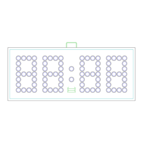
5. REPLACEMENT PARTS LIST 5.1 Scoreboard Display Parts figure 1 DISPLAY ASSEMBLY... - Page 11 REPLACEMENT PARTS LIST (MP-5203 Basketball) fig.& MFG PART VENDOR index NUMBER DESCRIPTION PART # 000000 Display Assembly 000000 150820 Cluster, Red 150820 151040 Controller Assembly 151040 SEE FIGURE 2 701036 Fuseholder, Single FSE 3453LF1 701049 Fuse, 3A 250V MDX-3 930895...
-
Page 12: Controller Assembly Parts
5.2 Controller Assembly Parts figure 2 CONTROLLER ASSEMBLY REPLACEMENT PARTS LIST (MP-5203) Controller Assembly fig.& MFG PART VENDOR index NUMBER DESCRIPTION PART # 151040 Controller Assy, MP-5299 151040 150635 Receiver Board, MP-5000 150635 150634 Driver Board, MP-5000 150634 BL00032P Power Supply, 50 Watt... -
Page 13: Diagrams
6. DIAGRAMS 6.1 Control Console Keyboard and Slipsheet Layout CONSOLE KEYBOARD... -
Page 14: System Layout
6.2 Scoreboard System Layout SYSTEM LAYOUT... -
Page 15: Single Wall Junction Box Wiring
6.3 Single Wall Junction Box Wiring SINGLE JUNCTION BOX WIRING... -
Page 16: Dual Wall Junction Box Wiring
6.4 Dual Wall Junction Box Wiring DUAL JUNCTION BOX WIRING... - Page 17 6.5 Controller Wiring Diagram CONTROLLER WIRING...
-
Page 18: Power Supply Diagram
6.6 Power Supply Diagram POWER SUPPLY... -
Page 19: Receiver Board Diagram
6.7 Receiver Board Diagram RECEIVER BOARD 6.8 Driver Board Diagram RECEIVER BOARD... -
Page 20: Figuregram Wiring
6.9 Figuregram Wiring Diagram FIGURGRAM WIRING... -
Page 21: Microprocessor 4 X 7 Led Pattern (8 Bit)
6.10 Microprocessor 4 X 7 LED Pattern (8 Bit) MICROPROCESSOR 4 X 7 (8 BIT) LED PATTERN... - Page 22 6.11 Installation Drawing INSTALLATION DRAWING...
Need help?
Do you have a question about the MP-5203 and is the answer not in the manual?
Questions and answers