Table of Contents

Subscribe to Our Youtube Channel
Related Manuals for Wenglor U2GT Series


Summary of Contents for Wenglor U2GT Series
- Page 1 U2GTxxx Ultrasonic Distance Sensor IO-Link Operating Instructions Translation of the original operating instructions Subject to change without notice Available as PDF file only Version 1.0.0 As of: 9/22/2023 www.wenglor.com...
-
Page 2: Table Of Contents
Index General .............................4 1.1 Information Concerning these Instructions .....................4 1.2 Explanations of Symbols ........................4 1.3 Limitation of Liability ..........................5 1.4 Copyrights ...............................5 For Your Safety........................6 2.1 Use for Intended Purpose ........................6 2.2 Use for Other than the Intended Purpose ....................7 2.3 Personnel Qualifications .........................7 2.4 Modification of Products .........................7 2.5 General Safety Precautions ........................7... - Page 3 7.4 Condition Monitoring/Process Data ..................... 31 7.4.1 Process Data In ........................31 7.4.2 Process Data Out ........................31 7.5 Events ..............................32 8. wTeach2 Configuration Software ..................32 Maintenance Instructions .....................32 10. Proper Disposal ........................32 11. Appendix ..........................33 11.1 List of Abbreviations .......................... 33 11.2 Change Index for Operating Instructions ...................
-
Page 4: General
1. General 1.1 Information Concerning these Instructions • These instructions apply to products designated U2GTxxx. • These instructions make it possible to use the product safely and efficiently. • These instructions are an integral part of the product and must be kept on hand for the entire duration of its service life. -
Page 5: Limitation Of Liability
• wenglor assumes no liability for printing errors or other inaccuracies contained in these operating instruc- tions unless wenglor was verifiably aware of such errors at the point in time at which the operating instruc- tions were prepared. -
Page 6: For Your Safety
2. For Your Safety 2.1 Use for Intended Purpose This sensor is used to measure distances. Ultrasonic sensors emit pulsed ultrasonic waves at a certain frequency using air as a transmitting medium. The sensors evaluate the transit time of the ultrasound reflected from the object. Parameters can be taught into the sensors shown here via an input or IO-Link. -
Page 7: Use For Other Than The Intended Purpose
• The product is not suitable for use in potentially explosive atmospheres. • The product may be used only with accessories supplied or approved by wenglor, or in combination with approved products. A list of approved accessories and combination products can be found at www.wenglor.com on the product detail page. -
Page 8: Approvals And Protection Class
2.6 Approvals and Protection Class IND. CONT. EQ 72HL / E189727 For use in class 2 circuits For Your Safety... -
Page 9: Technical Data
3. Technical Data 3.1 General Data Order Number U2GT001 U2GT002 U2GT003 U2GT004 Technical Data Ultrasound Data Working range, reflex sensor 50…600 mm 150…1,300 mm 50…600 mm 50…1,300 mm Working range, through-beam 1…1,200 mm 1…2,600 mm 1…1,200 mm 1…2,600 mm sensor Setting range 50…600 mm 150…1,300 mm... -
Page 10: Warm-Up Phase
Order Number U2GT001 U2GT002 U2GT003 U2GT004 Technical Data Error output Output A1 4…20 mA Output A2 3.2 Warm-Up Phase The warm-up phase lasts roughly 30 minutes. At the beginning of the warm-up phase, linearity deviation and reproducibility may deviate from the specified values. During the warm-up phase, the values improve in the form of an exponential function until the values in the technical data are reached. -
Page 11: Mode-Dependent Data
3.3 Mode-Dependent Data Some technical data depend on the filter set. Depending on the setting, the following data are obtained: Reflex and Through-beam Mode Switching frequency Filter value Response time in ms in Hz 10.0 * The specified switching frequency and response time correspond to the maximum duration including the inter- ference filter. -
Page 12: Sonic Cone Diagrams
3.4 Sonic Cone Diagrams 3.4.1 U2GT001/U2GT003 Measurement of sonic cone on plate 100×100 mm Measurement of the sonic cone on a rod with a diameter of 25 mm Ob = Object Standard sonic cone (center of the measured object) Sc = Sonic cone width Extra-narrow sonic cone (center of the measured object) Standard sonic cone (front edge of the measured object) NOTE! Please note that using multiple ultrasonic sensors can cause reciprocal influence. -
Page 13: U2Gt002/U2Gt004
3.4.2 U2GT002/U2GT004 Measurement of sonic cone on plate 100×100 mm Measurement of the sonic cone on a rod with a diameter of 25 mm Ob = Object Standard sonic cone (center of the measured object) Sc = Sonic cone width Extra-narrow sonic cone (center of the measured object) Standard sonic cone (front edge of the measured object) Ultrasonic Sensors... -
Page 14: Housing Dimensions
3.5 Housing Dimensions 1 = Active surface Dimensions specified in mm (1 mm = 0.03937") 3.6 Complementary Products wenglor can provide you with suitable connection equipment for your product. Suitable mounting technology no. Suitable connection technology no. U2GT001 and U2GT002... -
Page 15: Layout
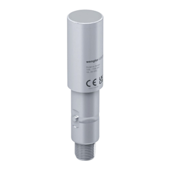
3.7 Layout 1 = Transducer 2 = Bayonet fastening 3 = Connector plug 3.8 Scope of Delivery • Ultrasonic Reflex Sensor U2GT0xx • Information sheet Ultrasonic Sensors... -
Page 16: Transport And Storage
4. Transport and Storage 4.1 Transport Upon receipt of shipment, inspect the goods for damage in transit. In the case of damage, conditionally accept the package and notify the manufacturer of the damage. Then return the device, making reference to damage in transit. -
Page 17: Installation And Electrical Connection
5. Installation and Electrical Connection 5.1 Installation For mounting the sensor, the hygienic fastenings provided by wenglor must be used to prevent the transmis- sion of vibrations into the environment. The use of other mounting techniques may lead to malfunction of the sensor, for which wenglor sensoric elektronische Geräte GmbH accepts no liability. -
Page 18: Electrical Connection
5.2 Electrical Connection • Wire the sensor in accordance with the connection diagram. • Switch on the supply voltage (see “3. Technical Data” on page U2GT001 and U2GT002: Wire colors: 1 = brown 2 = white 3 = blue 4 = black 5 = gray Supply voltage "+"... -
Page 19: Troubleshooting
• Shut down the machine. • Analyze and eliminate the cause of error with the aid of the diagnostics information. • If the error cannot be eliminated, please contact wenglor’s support department. • Do not operate in case of indeterminate malfunctioning. -
Page 20: Default Settings
6. Default Settings Technical Data U2GT001 U2GT002 U2GT003 U2GT004 Temperature mode Internal Internal Internal Internal A1 pin function Switching output Switching output Error output Error output A1 teach-in mode Foreground Foreground Foreground Foreground A1 PNP/NPN A1 NO/NC A1 switching point 600 mm 1,300 mm 600 mm... -
Page 21: Settings And Functions Overview
The process data transmit cyclical data and condition monitoring. To this end, the sensor is connected to a suitable IO-Link master (see product detail page/complementary products). The interface protocol and the IODD can be found at www.wenglor.com in the download area for the respective product. -
Page 22: Background Teach-In
7.1.2 Background Teach-In Sensor Teach-in distance Object Switching point 1. Install the sensor in accordance with the installation instructions. 2. Align the sensor to the background. 3. Configure or teach-in the switching output / the switching output function via IO-Link. 4. -
Page 23: Through-Beam Sensor Operating Mode
7.1.4 Through-Beam Sensor Operating Mode In addition to the reflex mode (default setting), a through-beam operating mode is also available. Two sensors are required to this end. 1. Set up one sensor as an emitter. 2. Set up another sensor as a receiver. 3. -
Page 24: Additional Functions And Settings
7.1.5 Additional Functions and Settings Filter The selected filter has an influence on the response time (see response time in section ““3. Technical Data” on page 9) and the number of distance values to be evaluated. Filter Description 0–15 Median filter Median filter from the specified number of measured valu- es. - Page 25 Filter Median filter of 28 measured values and bridging of 31 missing measured values (496 ms) Median filter of 28 measured values and bridging of 62 missing measured values (992 ms) NOTE! The technical data resulting from the various modes are specified in ““3.
- Page 26 Temperature The sensor has internal temperature compensation. Alternatively, the Internal mode temperature can be measured externally and sent to the sensor as a process or parameter. Internal Sensor operates with internal temperature compensation External Sensor works with external temperature compensation and uses the transmitted process or parameters (see section “„7.4 Condition Monito- ring/Process...
-
Page 27: Pin Functions
7.2 Pin Functions For U2GT001 and U2GT002 Possible Settings Default Switching Output Switching output Switching point SSC1 is assigned to the switching output. Error Output The error output switches if one of the assigned errors occurs; see table ““Status Messages” on page 29. Deactivated The pin is deactivated. -
Page 28: Input Functions
7.2.1 Input Functions The analog and switching outputs can be set via pin 5 using external teach-in: Function Possible Settings Default: Sup- ply Voltage Active Supply Voltage Active External Supply Voltage teach-in Function is triggered as soon as supply voltage is applied to the input. active Supply Voltage Inactive Function is triggered as soon as 0 V is applied to the input or the input is... -
Page 29: Condition Monitoring Functions
7.3 Condition Monitoring Functions 7.3.1 Status Message Function The sensor provides various status messages. Due to the process data structure, four status messages can be transmitted as individual process data. These parameters can be used to set the status messages that are transmitted via the process data. Function Possible Settings Default... -
Page 30: Simulation Functions
7.3.3 Simulation Functions This function simulates the behavior of the sensor regardless of the current status and measured value. This can be used to check whether a plant in which the sensor is integrated reacts correctly to the data supplied by the sensor and processes them accordingly. - Page 31 7.4 Condition Monitoring/Process Data The data described in the following section can be read or written cyclically via IO-Link/process data. 7.4.1 Process Data In Data Meaning Measured Measured distance in mm or 1/10 inch value As the sensor cannot determine a measured value in the following error cases, substitute values are read out: No signal: 0x7FFC / –...
- Page 32 • The product must be protected against contamination during initial start-up. 10. Proper Disposal wenglor sensoric GmbH does not accept the return of unusable or irreparable products. Respectively valid national waste disposal regulations apply to product disposal. wTeach2 Configuration Software...
- Page 33 11.2 Change Index for Operating Instructions Version Date Description/Changes 1.0.0 9/22/23 Initial version of the operating instructions 11.3 Declarations of Conformity Declarations of conformity can be found on our website at www.wenglor.com in the product’s separate down- load area. Ultrasonic Sensors...
Need help?
Do you have a question about the U2GT Series and is the answer not in the manual?
Questions and answers