
Related Manuals for Midea JL1850S-RO


Summary of Contents for Midea JL1850S-RO
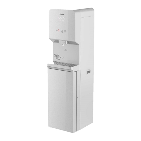
- Page 1 Service manual Water Purifier JL1850S-RO (Z80) When replacing parts, be sure to use specified parts at parts list for safety and performance maintenance...
-
Page 2: Table Of Contents
CONTENTS Safety instructure and accessories ..............3 Product Specification ..................5 Principle of operation ..................7 System Diagram ....................8 Construction Views ..................9~9 Product feature ....................10 Electrical schematics and wiring diagrams ............11 Preparation before operation of the water purifier ........12~15 The display panel is shown as below:............... -
Page 3: Safety Instructure And Accessories
Safety instruction and accessories (1) Safety instruction 16.Appliance the are obviously damaged must not operated. - Page 4 17.If the replacement of the UV-C emitter by the user is not allowed,this must be clearly stated. 18.WARNING: When positioning the appliance, ensure the supply cord is not trapped or damaged. 19.WARNING: Do not locate multiple portable socket-outlets or portable power supplies at the rear of the appliance.
-
Page 5: Product Specification
Product Specification... -
Page 7: Principle Of Operation
Principle of operation Supply water Supply power, all icons flash for 5 seconds, the product makes "beep" sound once Pressing the Heating/Cooling switch Flush (power on the pump, inlet valve, waste valve), duration is 25 seconds Low floater is closed, lack of water Water production (power on the Heating and Cooling is running... -
Page 8: System Diagram
Filter function System Diagram 1、the water flow inside of water purifier:... -
Page 9: Construction Views
2、the water flow outside of water purifier: Construction Views 1、Front 2、Back... -
Page 10: Product Feature
3、Left 4、 right 4、Top 5、bottom Product feature Product strong point Booster pump 1. Increase the pressure on the front end of the RO filter element; ensure the system works properly to produce purified water. 2. Rated voltage: 24V. 3. Rated current: ≤ 1A. 4. -
Page 11: Electrical Schematics And Wiring Diagrams
Electrical schematics and wiring diagrams WARNING: Disconnect electrical power before servicing. Caution: Label all wires prior to disconnection .Wiring errors can cause improper. -
Page 12: Preparation Before Operation Of The Water Purifier
Preparation before operation of the water purifier Installation procedure ο Setting the installation location ② Disassemble the package ③ Take out water purifier and accessories ④ Connection of water supply tube ⑤ Connection of drain tube ⑥ Open the water inlet valve. ⑦... - Page 13 4. Open the lower door . 5. Use the after sale accessory—filter flushing tip, the arrow direction is the water flow direction, insert the PE pipe in the quick joint. 6. Insert the C1 active carbon filter into the filter flushing tip, tighten it by turning anticlockwise, and open the water tap to flush the filter till it doesn't discharge black water, for about 10min;...
- Page 14 9. Insert the water inlet PE pipe in the quick joint, and tighten the pin. The new hose-sets supplied with the appliance are to be used and that old hose-sets should not be reused. 10. The water cooler plug cord into a ground fault interrupter receptacle. 11.
- Page 15 15. Machine Installation 1-2. Loosen the screw of the left or right bottom angle just as the picture shown. 3. Use the screw to fix the bracket on the left or right bottom angle of the water purifier. 4. Make a hole on the floor's or the desk's surface where the water dispenser will be installed.
-
Page 16: The Display Panel Is Shown As Below
The display panel is shown as below: 1. “ ” When displays as this, it indicates that water heating is completed. 2. “ ”When displays as this, it indicates that water is heating. 3. “ ”When displays as this, it indicates that water cooling is completed. 4. -
Page 17: Operational Precautions
5. Additional remarks Non-filter reset mode, the button functions are as follows: Button Operation Function Hot water + warm water Hold for 3 seconds Reset the expired filter Warm water + cold water Hold for 3 seconds Enter single filter reset mode Completed within 20 Child lock + cold water seconds after power-on... -
Page 18: Maintenance
instructions (except for the RO membrane filter).The RO membrane filter shall be flushed through the mode that repeatedly supply and cut off power of the whole machine for 10 times, and hold for 25 seconds each time. 5. Open the lower door, remove the old filter to be replaced, and replace it with a new filter. -
Page 19: Trouble Shooting
3. In case the machine is not in use for a long time, turn off the heating switch or the refrigerating switch to save power. 4. In case the machine is not needed for a long time, please take off the plug, turn off the copper chrome-plated ball valve and drain off the remaining water through the outlet. - Page 20 Source water quality is low Use municipal tap water Screen displays E0 Water leakage See the fault code troubleshooting method for details Screen displays Ec High floater is closed, low See the fault code troubleshooting floater is closed method for details Screen displays Ed The high floater is closed, See the fault code troubleshooting...
-
Page 30: Dismantling/Assembling
Dismantling/Assembling This instruction is for demonstration only; the actual operation can be adjusted accordingly Tools for disassembling The disassembly steps are as follows: Remove the rear cover plate Remove the 4 screws of Remove the condenser Remove the rear cover plate the condenser (do not bend the pipe) Replace... - Page 31 Remove replace the top cover Remove the 2 screws of the Lift the edge of the top State of top cover after top cover cover slightly to remove it opening from the front housing Remove the 2 screws of the Open the 2 buckles of the Open the water tank cover Remove...
- Page 32 Loosen the electric box, Remove the wires Remove the 2 screws from then you can see the whole the top bracket of the hot Remove hot tank tank replace the hot tank Unplug the pipes Hold the bottom of the hot tank and remove the hot tank to right for replacing it...
- Page 33 the bottom of the middle support for replacing it Remove the right screw Remove the screw with Open the lower door cover magnetic cross-headed screwdriver Remove replace the filter Lift the filter and turn the filter to the left to replace it (The new filter should be flushed with a special filter holder before installation...
-
Page 34: Introduction Of Key Electrical Components Parts
Remove the 6 screws on Pull out the door frame both sides Remove replace the front housing Remove the water tray, Remove the front 2 Press the front housing remove the 2 screw covers screws and the inner 5 down with both hands to of the front housing screws remove it from the side... - Page 35 Booster pump UV lamp Hot tank Temperature limiter Float switch Drainage solenoid valve Pressure reducing valve Inlet solenoid valve...
-
Page 36: Product Exploded Views And Part List
Flushing valve Product Exploded views and Part List Part Name Quantity BOM Code No. English Name Part Name Quantity BOM Code Lower door assembly Lower door assembly 12163100003082 Tempered glass panel Tempered glass panel 12563100000542 Lower door Lower door 12163100002966 Lower door lining Lower door lining 12163100003121... - Page 37 Magnetic Ring Magnetic Ring 10505701000048 Quick connector quick connector 12163200000366 Liquid level switch Liquid level switch 17463200004993 AC adapter AC adapter 17163200000423 Assembled tube Assembled tube 12663100001221 Anti-steam jacket anti-steam jacket 12163100001201 Display panel Display panel 17163100001985 Side handle side handle 12163000001804 Button board Button board...
- Page 38 Condenser Condenser 12963100000661 Support bar Support bar 12963000000099 Hot tank Hot tank 17463100001885 Solenoid valve solenoid valve 17463200A01143 Solenoid valve solenoid valve 17463200A00803 Small plastic parts small plastic parts 12163000001978 12163000002137 Cover type cover type 12163000001632 Temperature limiter temperature limiter 17463000000155 Assembled tube Assembled tube...
Need help?
Do you have a question about the JL1850S-RO and is the answer not in the manual?
Questions and answers