Table of Contents
Advertisement
Quick Links
Advertisement
Table of Contents

Subscribe to Our Youtube Channel
Related Manuals for RAIS VISIO 100 RD


Summary of Contents for RAIS VISIO 100 RD
- Page 1 VISIO GAS INSTALLATION MANUAL (GB) VISIO 100 RD VISIO 100 T...
- Page 2 1st edition 10.05.2023...
-
Page 3: Table Of Contents
INSTALLATION MANUAL CONTENTS INTRODUCTION Introduction to the installation manual The gas fireplace in general Safety Delivery packaging Overview of contents INSTALLATION Installation guide Installation preparations Removing the glass Mounting the glass Installing the burner Arranging ceramic logs Restrictors Installation of electrical and gas components Electrical connection Gas connection Retractable inspections grate (optional) -
Page 4: Introduction
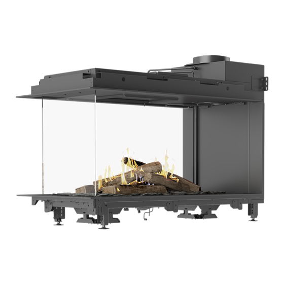
The installation manual covers the following two models: VISIO 9 Visio 100 RD Visio 100 RD – Room Divider model (three sides) Visio 100 T – Tunnel model (two sides) GENERAL INFORMATION It is important that the gas fireplace is correctly installed with consideration to the environment and people’s... - Page 5 INTRODUCTION WARNINGS Please note the symbols below that indicate potentially dangerous situations. SYMBOL DESCRIPTION Visual sign illustrating an important notice or caution. Visual sign illustrating a potential hazard. INSTRUCTIONS FOR USING QR CODES You will find QR codes with links to video guides for different installations in several places within the manual.
-
Page 6: The Gas Fireplace In General
NL, NO, RO, SE, SI, SK, TR G30/G31@50 I3B/P (50) 11,2 AT, CH, CZ, DE, FR, SK 32,4 - 39,6 Produced for: ATTIKA FEUER AG, Brunnmatt 16, CH-6330 Cham / RAIS A/S, Industrivej 20, DK-9900 Frederikshavn CE Label for: Visio Gas 22-06-2023... -
Page 7: Safety
INTRODUCTION SAFETY It is important that the gas fireplace is correctly installed there is no need for an extra air supply for combustion. with consideration to the environment and people’s It is recommended that the air replacement in the room safety. - Page 8 INTRODUCTION SAFETY DEVICES IN THE FIREPLACE The gas fireplace has three safety devices: thermocouple • Our fireplaces are fitted with a 1 thermocouple in the pilot unit. If the pilot flame is not lit, the fireplace will shut down. thermocouple •...
-
Page 9: Delivery Packaging
30-120 1000-2000 120-400 400-1000 Phone +45 98 47 90 33 - Fax +45 98 47 92 91 Material: Bend E-mail: info@rais.dk - Homepage: www.rais.dk TILLADTE AFVIGELSER FOR VINKELMÅL Drawing name: 0-10 10-50 50-120 120-400 >... -
Page 10: Overview Of Contents
INTRODUCTION OVERVIEW OF CONTENTS The following elements are included for decoration of the combustion chamber and fine tuning of airflow and flame image: CONTENTS 1. Logs (qty. 10) Please note that two of the ceramic logs must not be used. 2. - Page 11 INTRODUCTION OVERVIEW OF ELECTRONIC COMPONENTS Receiver GV60 combination valve Light module and adapter 12V OVERVIEW OF REMOTE OPTIONS WiFi module Remote control PUCK (optional) (optional)
-
Page 12: Installation Guide
Follow the separate instructions provided with the respective accessories. ARRANGING THE CERAMIC LOGS Follow the instructions on page 21 to arrange the ceramic logs for Visio 100 RD and Visio 100 T. RESTRICTORS Follow the instructions on page 29 for the overview and description. -
Page 13: Installation Preparations
INTRODUCTION INSTALLATION PREPARATIONS On this page, we have listed points to be aware of before starting the installation of the gas fireplace. NOTE! Placement and construction preparations • If the installation is made in an existing chimney, clean the chimney before installation. •... -
Page 14: Removing The Glass
INSTALLATION REMOVING/MOUNTING THE GLASS REMOVING THE GLASS The gas fireplace comes with the glass fitted. The glass must be removed to install the fireplace burner. Scan the QR code to watch a how-to-video The frames must be removed before removing the glass. NOTE! For safety purporses, never remove the front glass. - Page 15 INSTALLATION 3. Grip the two metal edges on the glass and pull the glass towards the front. 4. Lift the glass until it is free of the base frame. Tilt the bottom of the glass out and then down. 5. The glass can now be removed.
-
Page 16: Mounting The Glass
INSTALLATION MOUNTING THE GLASS When the glass is to be reinstalled, please follow the installation guide “Removing the glass” on page 14 by starting with the last step and be aware of the position indicator shown below. NOTE! There is a position indicator in the middle of the gas fireplace frame, which ensures the glass is fitted correctly. This wedge must fit between the two notches on the glass. -
Page 17: Installing The Burner
INSTALLATION INSTALLING THE BURNER If the burner is not installed on delivery, please follow The air settings for the burners varies between the these steps to fit the burner. gas types. Make sure that the correct air settings have been made, if not, please make the necessary Make sure that the burner fits the required gas type. - Page 18 INSTALLATION PROCEDURE Remove the burner and hose from the box. Remove the bottom grate from the combustion chamber. Remove the four fitted bolts on the bottom of the fireplace (see the arrows). WARNING! Incorrect installation can cause a dangerous situation. Make sure that the bottom bolts are tightened and that the burner is pressed against the bottom combustion chamber gasket.
- Page 19 INSTALLATION Fit the burner in the combustion chamber using the four screws. Check that the gasket between the burner and the fireplace base is intact. The burner must be mounted with the pilot flame towards the front of the appliance. If the exhaust is to the right (see the red circle), the pilot is in front.
- Page 20 INSTALLATION OVERVIEW OF THE BURNERS Main Secondary burner burner thermocouple Piezo electrode Pilot flame guide...
-
Page 21: Arranging Ceramic Logs
INSTALLATION ARRANGING THE CERAMIC LOGS When arranging the ceramic logs and the embers layer When commissioning or servicing the fireplace, it must in the combustion chamber, it is important that they be ensured that the cross ignition (from the pilot flame do not cover the pilot flame and its thermocouple, and to the main burner) functions, and that ignition occurs ember material must not be placed under the pilot... - Page 22 INSTALLATION LOG PLACEMENT – VISIO 100 RD AND VISIO 100 T The following ceramic logs must be used. A small elevation in log no. 7 can be used for identification 1. Start by securing the two secondary burners in the fireplace’s base plate.
- Page 23 INSTALLATION 2. Start from the opposite side of the pilot flame – and place ceramic log no. 1. 10 cm 7 cm 5.5 cm 3. Place ceramic log no. 2 so that it rests on log no. 1. 5.5 cm 6.5 cm...
- Page 24 INSTALLATION 4. Place ceramic log no. 3. 4 cm 13 cm 7 cm 7 cm 1 cm 5.5 cm 5. Then place ceramic log no. 4 on the secondary burner to the left.
- Page 25 INSTALLATION 6. Place ceramic log no. 5 on the other secondary burner to the right. 7 cm 7 cm 7. From the opposite side, place ceramic log no. 6. 21 cm 8 cm 5 cm...
- Page 26 INSTALLATION 8. Place ceramic log no. 7. 7 cm 7 cm 20 cm 1.5 cm 10 cm 9. Place ceramic log no. 8. 2.5 cm 1 cm 10 cm...
- Page 27 INSTALLATION 10. Now the glass pieces must be distributed in the combustion chamber. Measure 1.25 L of glass into a measuring cup. 11. Distribute the glass pieces (1.25 L in total) on both sides of the gas fireplace – over the LED lights. It is important that the pieces of glass are distributed in a thin layer that just exactly covers the holes in the bottom of the fireplace.
- Page 28 INSTALLATION 12. Now measure 3 L of the ember chips (a mixture of the grey and the black chips). 13. Sprinkle the ember chips over both the glass pieces and the rest of the base plate. WARNING! Be aware that the main burner and pilot flame are kept free of all ornaments. 14.
-
Page 29: Restrictors
INSTALLATION RESTRICTORS Three different restrictor are included for the gas fireplace. The restrictors are used to create the correct flow in the balenced flue. It is important to see and assess from the flame picture whether the correct restrictor is fitted. The flames should be blue/yellow at start-up, after 20 minutes the flames should be a clear yellow. -
Page 30: Installation Of Electrical And Gas Components
INSTALLATION INSTALLATION OF ELECTRICAL AND GAS COMPONENTS CONNECTION DIAGRAM Use the diagram to get an overview of the individual electrical and gas components. Pictures of the parts will be provided on the following pages. -
Page 31: Electrical Connection
INSTALLATION ELECTRICAL CONNECTION The following electrical parts accompany this gas fireplace: LED box Power supply/ Receiver adapter 12V CONNECTING THE LED BOX The LED box must be connected to the power supply (see arrow A). The LED box can be positioned on the retractable inspection grate (optional). -
Page 32: Gas Connection
INSTALLATION GAS CONNECTION PROCEDURE 1. Remove the strips holding the flexible gas lines Secure against leaks in all gas connections made. and wires together and place the parts carefully Make sure that the gas is correctly connected. under the fireplace. Make sure that no cables are disconnected. -
Page 33: Retractable Inspections Grate (Optional)
INSTALLATION RETRACTABLE INSPECTION GRATE (OPTIONAL) RETRACTABLE As an accessory for the built-in gas fireplaces, a INSPECTION GRATE retractable inspection grate is available. The retractable Scan the QR code grate covers the GV60 Combination Valve, receiver, etc., to watch a how-to-video and can easily be pulled out during, e.g. -
Page 34: Remote Control
INSTALLATION REMOTE CONTROL SYNCHRONISE THE REMOTE In this section you can learn how to set up the remote CONTROL control for the gas fireplace. Scan the QR code to watch a how-to-video The remote control uses 2 x AAA 1.5V batteries. Never use pointed tools to remove the batteries from the receiver and remote control. -
Page 35: Balanced Flue System
(C91). The fireplace may only be installed using a balanced flue (also known as balanced flue system) in the way stated by RAIS. The RAIS fireplace is approved with the Exodraft fan system. The flue pipes recommended by RAIS have been... -
Page 36: Positioning Flue Terminals
INSTALLATION POSITIONING FLUE TERMINALS The table below shows how different flue terminals can NOTE! Be aware that the safety distances below be positioned in the house and how large the safety are English national guides. Please follow distances must be. national regulatory requirements. -
Page 37: Placement And Construction
INSTALLATION PLACEMENT AND CONSTRUCTION Use insulation panels with a maximum thermal In cases where national regulations require that control conductivity of 0.10 W/m.K or a minimum thermal measurements are taken in the flue pipe and above the resistance of 10 K.m/W. Suitable products can be fireplace, a measuring spigot can be positioned here. -
Page 38: Distance To Combustible Material
INSTALLATION DISTANCE TO COMBUSTIBLE MATERIAL FRONT AND SIDE VIEW Min. 1000 Outlet mm to the convection: combustible Min. 300 mm ceiling Make a from the protecting ceiling plate if the ceiling is combustible Min. 500 mm to combustible material Min. 150 mm from the Min. - Page 39 INSTALLATION TOP VIEW Min. 150 Keep a free mm from the distance around back frame to the fireplace of combustible 50 mm to ensure material convection Min. 500 mm to combustible material Combustible material Non-flammable materials...
- Page 40 INSTALLATION DISTANCE TO THE COMBUSTIBLE SHELF If you want to position flammable material above your fireplace, you must follow these minimum requirements. IF A THEN B 50 mm Min. 200 mm 100 mm Min. 250 mm 150 mm Min. 300 mm 200 mm Min.
- Page 41 INSTALLATION DISTANCE FROM GLASS TO COMBUSTIBLE SIDE WALL Fireplace opening Non-flammable material Combustible material Fireplace opening 100 mm Min. 150 mm between edge of opening and wall...
- Page 42 INSTALLATION CONSTRUCTION EXAMPLE The installation of Visio 100 RD and Visio 100 T must be fitted with convection openings which have a minimum area of 200 cm above the fireplace and 200 below the fireplace. DEFINITION 1. Inlet convection 2. Natural convection 3.
-
Page 43: Fitting The Frame (Optional)
INSTALLATION FITTING THE FRAME (OPTIONAL) When the ceramic logs and embers layer are correctly positioned in the gas fireplace, refit the glass as described in the section “Mounting the glass” on page 14. PROCEDURE TO FIT THE FRAME: 1. Fit the frame in the top of the gas fireplace using the accompanying screws (see the arrows). 2. -
Page 44: Starting The Gas Fireplace
INSTALLATION STARTING THE GAS FIREPLACE SOUNDS Before igniting the fire for the first time, ensure that all the packaging, labels, etc., are removed from the The fireplace can emit a “clicking” sound when it is fireplace and the glass is cleaned. heating up and cooling down. -
Page 45: Purging The Gas Pipe
INSTALLATION PURGING THE GAS PIPE PURGING THE GAS PIPE When the gas supply is connected for the first time, the Scan the QR code supply lines will be filled with air. The gas supply can to watch a how-to-video then be purged by unscrewing the inlet pressure tap on the side of the burner. -
Page 46: Pressure Setting Adjustment
INSTALLATION PRESSURE SETTING ADJUSTMENT BURNER PRESSURE The fireplace should be pressure adjusted according Scan the QR code to the data sheets on page 55. “Inlet pressure” (supply to watch a how-to-video pressure to the GV60 Combination Valve) and “Burner pressure” (nozzle pressure) must ALWAYS be measured and, if necessary, corrected by an authorised installer. -
Page 47: Co And O 2 Measurement
There are two points. The point at the rear/right end “IN” is for O and the “FLUE OUT” is for CO measurements. Visio6 RAIS Visio Gas 43-49-65 RD-6 Visio6_Room_Divider_061022 CO measurements are done when the fireplace has been running at full load for 45 minutes, The value must not exceed the level of national requirements. -
Page 48: Maintenance
Make sure the fireplace is completely cold before you flame picture. begin. RAIS cannot be held liable for injuries that result from touching a hot fireplace. SERVICE PROCEDURE The fireplace must be inspected by an authorised The steps below can be used as a guideline. -
Page 49: Cleaning
Check the outside and inside of the fireplace for any damage and pay particular attention to gaskets. Only original RAIS spare parts may be used. CLEANING THE CERAMIC LOGS 1. Remove the ceramic logs as described in steps 1-3 in “Recommended Service Guideline”... -
Page 50: Warranty
MAINTENANCE WARRANTY MAINTENANCE OF YOUR GAS FIREPLACE RAIS offers a 2-year warranty on all gas fireplaces. The warranty period begins upon delivery of the product. We recommend having your gas fireplace inspected by a professional once a year to ensure the product’s The warranty –... -
Page 51: Troubleshooting And Errors
If you, against all expectation, should experience issues with your fireplace, please try the following steps. If the issues persist, please contact your RAIS dealer and state in which step the problem occurred. The most seen problem is lost connection between remote control and receiver due to lack of power. Therefore, we recommend changing the batteries in your remote and resetting the connection between the receiver and remote. -
Page 52: Error Codes On The Remote Control
TROUBLESHOOTING AND ERRORS ERROR CODES ON THE REMOTE CONTROL ERROR SYMPTOM POSSIBLE CAUSE CODE • No pilot within 30 sec. • No gas supply • Note: After 3 failed ignition sequences F06 • Air in pilot supply line is shown. •... -
Page 53: Error Codes On The App
TROUBLESHOOTING AND ERRORS ERROR CODES ON THE APP ERROR MESSAGE SYMPTOM POSSIBLE CAUSE CODE SHOWN IN APP • 5 sec. beep from the receiver • Microswitch not making contact with the cam on the Contact Service • Fire is not responding, no ignition motor knob •... -
Page 54: Technical Information
NL, NO, RO, SE, SI, SK, TR G30/G31@50 I3B/P (50) 11,2 AT, CH, CZ, DE, FR, SK 32,4 - 39,6 Produced for: ATTIKA FEUER AG, Brunnmatt 16, CH-6330 Cham / RAIS A/S, Industrivej 20, DK-9900 Frederikshavn CE Label for: Visio Gas 22-06-2023... -
Page 55: Technical Data Sheets
TECHNICAL INFORMATION TECHNICAL DATA SHEET – NATURAL GAS Visio 100 RD and Visio 100 T (Visio 9) -
Page 56: Lpg
TECHNICAL INFORMATION TECHNICAL DATA SHEET – LPG Visio 100 RD and Visio 100 T (Visio 9) -
Page 57: Drawings
DRAWINGS VISIO 100 RD 1159 1159 1102,5 1102,5 1218,5 1218,5 Without frame With frame Without frame With frame... - Page 58 DRAWINGS VISIO 100 T 1173 1173 1024 1024 1122 1122 4 ( G With frame Without frame Without frame With frame...
- Page 60 RAIS A/S Industrivej 20 DK-9900 Frederikshavn Denmark www.rais.com...
Need help?
Do you have a question about the VISIO 100 RD and is the answer not in the manual?
Questions and answers