
Related Manuals for CAT Pumps 7CP6111CS


Summary of Contents for CAT Pumps 7CP6111CS
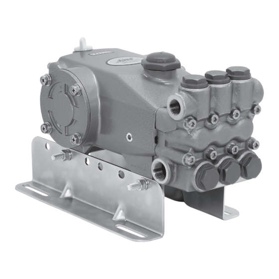
- Page 1 SERVICE MANUAL 7CP STAINLESS STEEL PLUNGER PUMPS PUMP MODELS INCLUDED 7CP6111CS 7CP6111CCS 7CP6111CSG1 7CP6171CS 7CP6171CCS Product Quality, Reliability and Support You Expect www.catpumps.com...
-
Page 2: Table Of Contents
Table of Contents Safety Symbols IMPORTANT SAFETY INSTRUCTIONS Safety Symbols It is the responsibility of the user to read and understand all General Safety Information instructions, important safeguards and safety precautions before Seal & Valve Kits operating or servicing any pump. Failure to do so may result in Service Intervals property damage, personal injury or death. -
Page 3: General Safety Information
General Safety Information A. FLAMMABLE OR EXPLOSIVE LIQUID HAZARD Do not operate pump with flammable or explosive liquids unless extraordinary safety precautions are observed. Leaks of flammable or explosive liquids, if exposed to elevated temperatures, static electricity, sparks or other hazards, will result in flame or possible explosion, causing serious personal injury, death or property damage. - Page 4 General Safety Information and Symbols F. OVER PRESSURIZATION HAZARD CONTINUED Do not operate high-pressure pumping system unless extraordinary safety precautions are observed. A high-pressure pumping system can deadhead or over pressurize causing serious personal injury and property damage. 1. All high-pressure systems require a primary pressure regulating device (e.g., regulator or unloader) and a secondary pressure safety relief device (e.g., pop-off valve, safety valve, rupture disc) to assure proper pressure setting and overpressure protection.
- Page 5 1. Fill pump crankcase to specific capacity indicated on data sheet or service manual prior to startup. 2. Cat Pumps premium custom-blend oil is available worldwide in 21-ounce bottles, (single and 12-pack cases), 2.5 gallon jugs (single and 2-pack) or 30 gallon drums. Use of other oils may void the warranty.
-
Page 6: Seal & Valve Kits
The seals on our pumps, operating under normal conditions, will perform for a minimum of 1500 hours, with most lasting much longer. The valves typically perform for 3000 hours, with many lasting much longer. Cat Pumps always recommends replacing these items as a kit since components usually wear at about the same rate. -
Page 7: Seal & Valve Kit Pump Diagram
Seal & Valve Kit Pump Diagram SEAL KIT COMPONENTS PN 76933 | Qty 1 VALVE KIT COMPONENTS PN 76387 | Qty 2 Plunger Retainer O-Ring Low-Pressure Seal O-Ring VALVE KIT V-Packings ASSEMBLIES 76387 Tools Needed 1. 6 mm Hex Wrench 2. -
Page 8: Servicing The Seals
Servicing the Seals MANIFOLD AND SEAL REMOVAL NOTE: One (1) seal kit is required to repair the pump. 1.01 Use a 6 mm hex wrench to remove the 1.02 Rotate the crankshaft with an 1.03 Insert two (2) large flat tip screwdrivers eight (8) hex socket head (HSH) screws adjustable wrench to create separation on opposite sides to pry the manifold... - Page 9 Servicing the Seals MANIFOLD AND SEAL REMOVAL 1.10 Inspect the seal case O-rings for cuts, 1.11 Inspect the grooved V-packing surface 1.09 Using a pick, remove the seal case nicks or damage. of the seal cases for scoring or damage. O-rings.
-
Page 10: Plunger Removal
Servicing the Seals PLUNGER REMOVAL 1.16 Remove seal retainers from crankcase 1.17 Using a 12 mm combination wrench, 1.18 Before completely removing the housing. loosen the plunger retainers. plunger retainers, stop and push the plungers towards the drive end to break loose from the retainers. -
Page 11: Plunger Reassembly
Servicing the Seals PLUNGER REASSEMBLY 1.24 Install barrier slingers with dish side 1.25 Install new plunger retainer O-rings 1.26 Apply a lubricant to outside surfaces of facing away from crankcase. between backup ring and head of the the plunger retainer O-rings. retainer. -
Page 12: Seal Installation
Servicing the Seals SEAL INSTALLATION NOTICE: Examine manifold for grooves, pitting or wear and replace as needed. 1.34 Install the second V-packings with the 1.33 One side of the V-packing has a groove. 1.32 Install the male adapters with the flat grooved sides also facing down. -
Page 13: Manifold Reassembly
Servicing the Seals MANIFOLD REASSEMBLY 1.39 Install manifold by hand, ensuring 1.40 Use a rubber mallet to tap manifold 1.38 Rotate crankshaft so outside two even alignment. on the rest of the way. plungers are even at furthest distance from crankcase. TORQUE SEQUENCE 1.41 Install eight (8) HSH screws by hand. -
Page 14: Servicing The Valves
Servicing the Valves VALVE REMOVAL NOTES: Two (2) valve kits are required to repair the pump. Discharge and inlet valve assemblies are identical (use procedure below for disassembly and reassembly of discharge and inlet valves). 2.02 Using a pick, remove O-rings from valve 2.03 Inspect valve plug O-rings for cuts, nicks 2.01 Use a 27 mm socket with ratchet to plugs. -
Page 15: Valve Reassembly
Servicing the Valves VALVE DISASSEMBLY 2.08 Inspect springs for proper tension or 2.09 Inspect tapered surfaces of the valves 2.10 Inspect tapered surfaces of valve seats any damage. for wear, pitting or damage. for wear, pitting or damage. NOTICE: Pitting on the valve seat or valve is an indication of cavitation.Review our Cavitation Troubleshooting Support Document for assistance. -
Page 16: Valve Installation
Servicing the Valves VALVE REASSEMBLY 2.16 Place spring retainers onto valve seats. 2.17 Using a rubber mallet, lightly tap spring 2.18 Replace valve seat O-rings into the top retainers into place. of the groove, then backup rings at the bottom. VALVE INSTALLATION 2.19 Apply a lubricant to outside surface of 2.20 Insert valve assemblies into manifold... -
Page 17: Reference Information
If contamination is suspected, inspect and replace the seals in the pump manifold, then clean out the inside of the crankcase and change the oil. Spot-check the following areas for signs of leaks and contact Cat Pumps or a local distributor for servicing crankcase if needed. Drain Plug... -
Page 18: Pump Rotation
Cat Pumps recommends using our custom-blend premium grade hydraulic oil formulated to meet Cat Pumps specifications. For best results, perform an initial oil change after the first 50 hours of operation and every 500 hours thereafter. -
Page 19: Torque Chart
Reference Information TORQUE CHART PUMP ITEM THREAD TOOL SIZE TOOL PART NUMBER TORQUE IN-LBS FT-LBS Plunger Retainers 12 mm Combination Wrench — Manifold Screws 6 mm Hex Wrench — 9.58 Valve Plugs 27 mm Hex Socket with Ratchet — 72.5 98.0 Rear Cover Screws 10 mm Combination Wrench... -
Page 20: Diagnosis And Maintenance
For International Inquiries go to www.catpumps.com and navigate to the “Contact” link. ©2023 Cat Pumps. All written and visual data contained in this document reflects the latest product information available at the time of publication. Cat Pumps reserves the right to make changes at any time without notice.
Need help?
Do you have a question about the 7CP6111CS and is the answer not in the manual?
Questions and answers