
Related Manuals for Omron C2UW-L DA Series


Summary of Contents for Omron C2UW-L DA Series
- Page 1 PNSPO ワイヤレスハンドスイッチ / Wireless Hand Switch 形C2UW-L DAシリーズ / Type C2UW-L DA series ユーザーズマニュアル / User’s Manual 第1版 Ed. 1.0 C2UW-LP-I DA + C2UW-LU DA 2847313-8A 2018/08...
- Page 2 • これら商標 を使用する許可を受けて本書に記載しています。 • Bluetooth® word marks and logos are trademarks owned by Bluetooth SIG, Inc. Omron Corporation is listed in this document with permission to use these trademarks. その他、本文中に掲載している会社名および製品名は、それぞれ各社の商標または登録商標です。 Other company names and product names in this document are the trademarks or registered trademarks of...
-
Page 3: Table Of Contents
目次 / Table of contents 目次 / Table of Contents はじめに / Introduction ・・・・ 5 対象となる読者の方 / Intended Audience 対象となる製品 / Applicable Products ご承諾事項 / Warranty and Limited Warranty ・・・・ 6 安全上の注意 / Safety Precautions ・・・・ 12 安全に使用していただくための表示と意味について / Indications to Ensure Safe Use, and Meanings of These Indications 安全上の要点... - Page 4 目次 / Table of contents 第3章 各種機能 / Functions ・・・・43 3-1 機能一覧 / List of Functions ・・・・44 3-2. 機能説明 / Function ・・・・46 3-2.1 ペアリング機能 / Bluetooth® Pairing Function ・・・・46 3-2.2 誤操作防止機能 / Grip safety with Touch sensor ・・・・47 3-2.3 表示機能 / Indicator ・・・・51 3-2.4 ホルダイン操作機能...
-
Page 5: はじめに / Introduction
はじめに / Introduction はじめに / Introduction このたびは、形 C2UW-L無線ハンドスイッチユニットをお買い上げいただきまして、ありがとうございます。 本マニュアルは、 形C2UW-Lを使用する上で、必要な情報を記載しています。お使いになる前に本マニュ アルをよくお読みいただき、機能・性能などを十分ご理解いただき、ご使用下さい。 また、お読みになった後も本マニュアルは大切に保管して、いつも手元においてお使いください。 Thank you for purchasing a C2UW-L series Wireless Hand Switch Unit. This manual contains information that is necessary to use the C2UW-L. Please read this manual and make sure you understand the functionality and performance of the C2UW-L series before you attempt to use it in your systems. -
Page 6: ご承諾事項 / Warranty And Limited Warranty
Omron electronic components information website, etc. (3) 「利用条件等」:「カタログ等」に記載の、「当社商品」の利用条件、定格、性能、動作環境、取扱い方 法、利用上の注意、禁止事項その他 Usage conditions : Usage conditions, rating, performance, operating environment, handling instructions, cautions, prohibited use, etc. of Omron products described in catalogues. (4) 「お客様用途」:「当社商品」のお客様におけるご利用方法であって、お客様が製造する部品、電子 基板、機器、設備またはシステム等への「当社商品」の組み込み又は利用を含みます。 Customer application Omron products... - Page 7 It is not intended to warrant rated values and performance values for multiple combined conditions. (2) 参考データはご参考として提供するもので、その範囲で常に正常に動作することを保証するものでは ありません。 Omron Omron products Reference data are provided for reference only. does NOT warrant that work properly at all time in the range of reference data. (3) 利用事例はご参考ですので、「当社」は「適合性等」について保証いたしかねます。...
- Page 8 (5) 「当社商品」は、一般工業製品向けの汎用品として設計製造されています。従いまして、次に掲げる 用途での使用は意図しておらず、お客様が「当社商品」をこれらの用途に使用される際には、「当社」 は「当社商品」に対して一切保証をいたしません。 Omron products are designed and manufactured as general-purpose products for use in general industrial products. They are not intended to be used in the following applications. If you are using Omron products Omron Omron...
- Page 9 (d) 「カタログ等」に記載のない条件や環境での用途 Applications under conditions and environment not described in catalogues. (6) 上記3.(5)(a)から(d)に記載されている他、「本カタログ等記載の商品」は自動車(二輪車含む。以下同 じ)向けではありません。自動車に搭載する用途には利用しないで下さい。 Omron products In addition to the applications listed from (a) to (d) above, are not intended for use Omron products in automotive applications (including two wheel vehicles). Please do NOT use...
- Page 10 Omron personnel. (d) 「当社」以外の者によるソフトウェアプログラムによる場合 Software program embedded by other than Omron or usage of such software. (e) 「当社」からの出荷時の科学・技術の水準では予見できなかった原因 Causes which could not have been foreseen with the level of science and technology at the time Omron of shipping from (f) 上記のほか「当社」または「当社商品」以外の原因(天災等の不可抗力を含む)...
- Page 11 ご承諾事項 / Terms and Conditions Agreement 5. 責任の制限 / Limitation of Liability 本ご承諾事項に記載の保証が「当社商品」に関する保証のすべてです。「当社商品」に関連して生じた損 害について、「当社」および「当社商品」の販売店は責任を負いません。 Omron products The warranty set out in these Terms and Conditions is the whole and sole liability for Omron Omron products There are no other warranties, expressed or implied.
-
Page 12: 安全上の注意 / Safety Precautions
安全上の注意 / Safety Precautions 安全上の注意 / Safety Precautions 安全に使用していただくための表示と意味について Indications to Ensure Safe Use, and Meanings of These Indications 本マニュアルでは、当製品を安全に使用していただくために、注意事項を次のような表示と図記号で示し ています。ここで示した注意事項は、安全に関する重大な内容を記載しています。必ず守ってください。 表示と図記号は次のとおりです。 ・図記号の意味 ・一般的な注意 特定しない一般的な注意喚起の通告 The following signal words are used in this manual. ・Meanings of Signal Words Indicates a potentially hazardous situation CAUTION which, if not avoided, may result in minor or moderate injury or in property damage. -
Page 13: 安全上の要点 / Precautions For Safe Use
安全上の要点/Precautions for Safe Use 安全上の要点 / Precautions for Safe Use 分解・落下 / Disassembly and Dropping • 本製品を、分解して修理や改造はしないでください。故障や発火の恐れがあります。 Do not attempt to disassemble, repair, or modify any Units. Doing so may result in malfunction or fire. • 製品を落下させたり、異常な振動・衝撃を与えたりしないでください。製品の故障、焼損の可 能性があります。 Do not drop any Unit or subject it to abnormal vibration or shock. Doing so may result in Unit malfunction or burning. - Page 14 安全上の要点/Precautions for Safe Use 使用時 / Usage • バッテリ交換時はCR17345(CR123A)規格のリチウム一次電池のみをご使用ください。交換 用には、製造年月が 1 年以内のものを使用してください。 When you replace the Battery, use only the CR17345(CR123A) standard Lithium primary cell. Be sure to install a replacement Battery within one years of the production date shown on the Battery label. •...
-
Page 15: 使用上の注意 / Precautions For Correct Use
使用上の注意 / Precautions for Correct Use 使用上の注意 / Precautions for Correct Use 保管時、設置時 / Case of Storage and Setting • 次のような環境に設置や保管しないでください。運転停止、誤動作する可能性があります。 Do not operate or store the Controller in the following locations. Operation may stop or malfunctions may occur. a) 日光が直接当たる場所・屋外 Locations subject to direct sunlight or outdoor 周囲温度や相対湿度が仕様値の範囲を超える場所... - Page 16 使用上の注意 / Precautions for Correct Use 使用時 / Case of Usage • スイッチの耐久性は開閉条件により大きく異なります。使用にあたっては必ず実使用条件にて実機確 認を行い、性能上問題のない開閉回数内にてご使用ください。 The durability of the switch varies greatly depending on the On/Off conditions. Be sure to check the actual machine under actual use conditions before use, please use within the On/Off times that does not cause any problem in performance.
- Page 17 使用上の注意 / Precautions for Correct Use 無線に関する注意事項 / Note about Wireless 無線ハンドスイッチはBluetooth ® を使用します.以下の環境でご使用になると通信エラーが発生 することがあります。 周囲の環境をご確認の上、使用してください。 The wireless hand switch uses Bluetooth ® . Communication error may occur if you use in the following environment. Please check the surrounding environment before using. 使用中に通信途絶(ハンドスイッチのリングLEDが点滅)が頻発する場合は機器の操作が安全に...
-
Page 18: 法規と規格 / Regulations And Standards
法規と規格 / Regulations and Standards 法規と規格 / Regulations and Standards 海外でのご使用 / For Overseas Use 本製品のうち、外国為替および外国貿易管理法に定める輸出許可、承認対象貨物(または技術)に該当 するものを輸出(または非居住者に提供)する場合は、同法に基づく輸出許可、承認(または役務取引許 可)が必要です。 If you export (or provide non-resident) export licenses prescribed in the Foreign Exchange and Foreign Trade Control Law and those that fall under the subject cargo (or technology) to be approved, the export license, approval (Or service trade permission) is required. - Page 19 法規と規格 / Regulations and Standards 無線認証 / Wireless Certification 以下の地域と国で無線認証を取得済みです。 Wireless certification has been acquired in the following regions and countries. 国 管轄機関または規格 エリア Regions Countries Agents or Standards, Directive The United アメリカ Federal Communications Commission (FCC) 北米 States of America /North America カナダ...
-
Page 21: 用語の説明 /Terminology
用語の説明 / Terminology 用語の説明 / Terminology 用語 Term 定義 Definition 形C2UW-Lを構成するユニットのうち、ユーザが手に持って操作する2ポジ ション押しボタンスイッチとサブスイッチを搭載する無線式のハンドスイッ チ。 無線ハンドスイッチ BLE MASTERデバイスとして動作します。 Wireless hand 本マニュアルでは以後、ハンドスイッチと略称します。 switch One of the units that make up the C2UW-L. Wireless hand switch carries two position push button switch and sub switch which the user holds by hand. - Page 22 用語の説明 / Terminology 用語 Term 定義 Definition 電極部分に人体が触れたか否かを静電容量の増減により検出するセン サ。 ハンドスイッチのグリップ部に内蔵しています。 タッチセンサ Touch sensor A sensor that detects whether a human body touches the electrode part by increasing or decreasing the electrostatic capacitance. It is built in the grip part of the hand switch. ホルダからハンドスイッチを取り出した後、設定した時間が経過するとハ...
-
Page 23: 改訂履歴 / Revision History
改訂履歴 / Revision History 改訂履歴 / Revision History 版 改定年月 改定内容 Revision Year/month Change points 発行 ED.1 2018/08 New Release... - Page 25 製品概要 / Product Overview...
-
Page 26: 特徴 / Features
1.製品概要 / Product Overview 1-1 特徴 / Features 概要 / Overviews • Bluetooth® Low Energy(BLE)を採用した無線リモコンスイッチです。 Wireless remote control switch using Bluetooth® Low Energy(BLE). • シングルアクション2ポジションのメインスイッチとサブスイッチを備えます。 Equips main switch with two-position contacts by single action, and sub switch. • デッドマンスイッチ機能を備えます Equips Dead man switch Function. •... -
Page 27: 各部名称 / Part Names
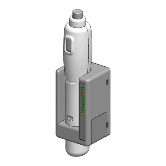
1.製品概要 / Product Overview 1-2 各部名称 / Part Names C2UW-Lの各部名称について説明します。 This section describes the names of each parts. 1-2.1 無線ハンドスイッチ / Wireless Hand-switch 正面/Front 背面/Rear バッテリカバーなし without Battery Cover メインスイッチ/ Main switch SW1:1段目 /1 Position SW2:2段目 /2 Position サブスイッチ SW3 Sub switch タッチセンサ... - Page 28 1.製品概要 / Product Overview 1-2.2 無線ホルダ / Wireless Holder 正面 / Front 背面 / Back 表示部 Indicators ←LED1 取付用ネジ穴 ←LED2 Screw Hole For Mounting ←LED3 ←LED4 ←LED5 ←LED6 ←LED7 フックロック 製品ラベル Hook Lock Product Label 右側面 / Right Side 右側面(カバーなし) / Right Side without Cover ファンクションスイッチ1 Function Switch 1 ファンクションスイッチ2...
-
Page 29: 用途例 / Application Examples
1.製品概要 / Product Overview 1-3 用途例 / Application Examples 呼び出しボタン / Call Switch ■病床からの呼び出し / Call from the bedside 配線レスのため、ケーブルの断線の心配がなく、操作の邪魔になりません。 Because there is no wiring, there is no worry of disconnection of the cable, it will not disturb the operation. ■作業現場からの呼び出し... -
Page 30: 使い方 / How To Use
1.製品概要 / Product Overview 1-4 使い方 / How To Use 1-4.1 推奨する使い方 / Recommended Usage ハンドスイッチはバッテリー駆動です。 電池の消費を抑えるため、ハンドスイッチをホルダから取りだして操作する時間を極力抑え、使用後は速 やかにホルダに戻してスリープモードにする使い方を推奨します。 In order to reduce the consumption of batteries, it is recommended to minimize the time to operate the hand switch (the time taken out from the holder) and return it to the holder immediately after use (put it into sleep mode). - Page 31 1.製品概要 / Product Overview 1-4.2 ハンドスイッチ操作とホルダの応答 / Behavior of the HOLDER ハンドスイッチの各スイッチを操作するとホルダから対応する信号が出力されます。 By operating each switch of the HAND-SWITCH, the corresponding signal is output from the holder. 対象 SW1 押下 SW2 押下 SW3 押下 Pressing SW1 Pressing SW2 Pressing SW3 ハンドスイッチ...
- Page 32 1.製品概要 / Product Overview 1-4.3 ホルダ操作とハンドスイッチの応答 / Wireless Holder Operation ホルダに入力した信号に応じてハンドスイッチのLEDが点灯します。 According to the signal input to the HOLDER, the LED of the HAND-SWITCH lights. IN_READY1 Input IN_READY1 IN_READY2 +IN_READY2 ホルダへの 信号⼊⼒ Input signal to Holder IN_READY1 IN_READY2 IN_READY1 +IN_READY2 ハンドスイッチ...
- Page 35 製品仕様/Product Specifications...
-
Page 36: 外形図 / Outline Drawings
2.製品仕様 / Specifications 2-1 外形図 / Outline Drawings 2-1.1 無線ハンドスイッチ / Wireless Hand Switch 2-1.2 無線ホルダ / Wireless Holder... -
Page 37: 機械的性能 / Mechanical Performances
2.製品仕様 / Specifications 2-2 機械的性能 / Mechanical Performances 2-2.1 機械的特性(初期) / Mechanical Characteristics (initial) 無線ハンドスイッチ C2UW-LP-I 備考 単位 項目 規格値 略号 Unit Notes ITEM Spec. Symbol 操作力1 メインSW 1段目 4.7±1.5 Operation Force1 SW1 1 level 操作力2 メインSW 2段目 12.6±3.0 Operation Force2 SW1 2 level メインスイッチ... -
Page 38: 電気的性能 / Electrical Performances
2.製品仕様 / Specifications 2-3 電気的性能 / Electrical Performances 2-3.1 電気的定格 / Electrical Ratings 無線ハンド スイッチ 無線ホルダ C2UW-LP-I C2UW-LU 電源電圧 2.5 to 3.3VDC 10.8 to 26.4VDC /Voltage for Operation 以下の規格要件を満たすLPS電 CR17345(CR123A)または同規 源にて電源供給すること。 格のリチウム1次電池。 Supply power with LPS power supply that meets Only available for use. - Page 39 2.製品仕様 / Specifications 2-3.2 絶対最大定格 / Absolute Maximum Ratings Ta=25°C 2-3.2 1)無線ハンドスイッチ絶対最大定格 / About Hand-switch 電源 印可電圧 電流(定常時) Power Source Applied Voltage Current(Stable state) VIN-GND Min: -0.2VDC/Max: 3.5VDC Max 0.5A 2-3.2 2)無線ホルダ絶対最大定格 / About Holder 電源 印可電圧 電流(定常時) Power Source Applied Voltage Current(Stable state) VIN-GND...
- Page 40 2.製品仕様 / Specifications 2-3.3 電池交換頻度 / Frequency of battery replacement ハンドスイッチの電池交換頻度は以下の通りです。余裕を持った定期交換をお願いします。 The battery replacement frequency of the hand switch is as follows. Please exchange regularly with a margin. 2回以上/年(下表使用条件の場合の参考値:お使いの電池の状態・環境条件により変動します) 2 times or more a year. (For Reference in the case of the following use condition : It varies depending on the condition of your battery and environmental conditions) 項目...
-
Page 41: 無線性能 / Wireless Performances
スレーブデバイス Master or Slave BLE Master Device BLE Slave Device プロファイル オムロン 独自プロファイル Profile OMRON original profile 2.4 GHz(2.401GHz~2.481GHz) ※備考:本製品を使用すると電波干渉が発生することがあります。 周波数 また,本製品は周囲の環境から電波障害を受けることがあります。 Frequency Notes: Under using this product, radio interference may occur. Also, this product may receive radio interference from surrounding environments for example other Wi-Fi instruments. - Page 43 各種機能 / Functions...
- Page 44 3.各種機能 / Functions 3-1 機能一覧 / List of Functions C2UW-Lの機能一覧です。 The function list of C2UW-L 概要/Overview 機能/Functions ペアリング ハンドスイッチ(BLE MASTER DEVICES)とホルダ(BLE SLAVE DEVICES)を相互に Pairing 接続し暗号化通信を可能とする機能。 ホルダの設定モードで登録・削除を⾏います。 The function that connects a hand switch (BLE MASTER DEVICES) and a holder (BLE SLAVE DEVICES) to enable encrypted communication. Can register / delete in setting mode.
- Page 45 3.各種機能 / Functions 概要/Overview 機能/Functions 表示 ハンドスイッチ、ホルダ、それぞれが設定状態や動作状態をLEDで表示するための機能。 The function for displaying the setting state and operating state of wireless LED indicators hand switch and holder with LED. ホルダイン検知 ハンドスイッチがホルダにセットされた状態を検知する機能。 Holder-in A function to detect whether the hand switch is set in the holder. sensor...
- Page 46 3.各種機能 / Functions 3-2 機能説明 / Function 3-2.1 ペアリング機能 / Bluetooth® Pairing Function 3-2.1 1) 概要 / Overview 当製品はBluetooth ® Low Energy規格の無線デバイスです。 ご購入後、はじめてご使用の際は、Master Deviceであるハンドスイッチと、Slave Deviceであるホルダのペ アリングを行う必要があります。 This product is a wireless device based on Bluetooth Low Energy standard. Before using, you need to pair the Hand Switch which is the master device and the Holder which is the slave device.
- Page 47 3.各種機能 / Functions 3-2.2 誤操作防止機能 / Grip safety with Touch sensor 3-2.2 1) 概要 / Overview 無線ハンドスイッチは誤操作防止のためのタッチセンサを内蔵しています。 本機能を有効とすることで、落下や意図しないスイッチ押下による誤操作を抑制します。 The wireless Hand Switch is embedded with touch sensors to prevent miss operation. By enabling this function, we can prevent miss operation by dropping or unintentional pushing. 対象となる操作はメインスイッチ(SW1およびSW2)です。...
- Page 48 3.各種機能 / Functions 3-2.2 2) 推奨する持ち方 / Recommended Grasp タッチセンサを有効設定でご使用いただく場合は、以下の持ち方をしていただくことを推奨いたします。 When using hand switch with touch sensor enabled, please sure to grasp as following . タッチセンサーの電極部分を手の平で覆ってしっかりと保持してくだ さい. スイッチ操作を有効にするには,4つ有る電極のうち2つ以上の電極 に触れる必要があります. スイッチを操作している間は,握り方を変えないでください. タッチセンサーの電極から手を放すと,スイッチを押していてもホルダ の出力が中断されます. Please cover the electrode part of the touch sensor firmly with the palm of your hand.
- Page 49 3.各種機能 / Functions 3-2.2 3) 感度キャリブレーション / Touch Sensor Calibration C2UW-LP-Iハンドスイッチが搭載するタッチセンサーは感度補正機能(キャリブレーション)を持ちます。 キャリブレーションは、ハンドスイッチをホルダにセットすることで実行されます。 The touch sensor mounted on the C2UW - LP - I hand switch has a sensitivity correction function (calibration). The calibration is executed when the hand switch set in the holder. 電池交換を行った際はすぐにキャリブレーションを実行してください。...
- Page 50 3.各種機能 / Functions キャリブレーションの失敗 / Calibration failure: キャリブレーションに失敗した場合、ハンドスイッチ下部のリングLEDが緑→黄と点灯します。 If calibration fails, the ring LED at the bottom of the hand switch lights green to yellow. この場合は、キャリブレーション内容は破棄されタッチセンサの感度はホルダにセットする前の状態になり ます。 失敗したらもう一度ハンドスイッチをホルダにセットし直してください。 In this case, the calibration value is discarded and the sensitivity of the touch sensor becomes the state before setting it in the holder.
- Page 51 3.各種機能 / Functions 3-2.3 表示機能 / Indicator 3-2.3 1) 無線ホルダ / Wireless Holder C2UW-LU無線ホルダは以下の表示機能を持ちます。 表示 説明 Display (色Color) Description (Meanings) LED1(緑) ホルダに電源が供給されて起動した際に点灯します(常時点灯)。 /It lights up when power is supplied to the Holder and starts up (POWER) (Normally ON). LED2(橙) BATT ハンドスイッチのバッテリ状態を表示します。常時消灯。...
- Page 52 3.各種機能 / Functions 3-2.3 2) 無線ハンドスイッチ / Wireless Hand-switch C2UW-LP-I無線ハンドスイッチは以下の表示機能を持ちます。 The C2UW-LP-I wireless hand switch has the following functions. • ホルダへの入力信号に応じた表示/Display according to the input signal to the holder ホルダへのIN_READY1及びIN_READY2信号の入力に応じて、リングLEDが点灯します。 The ring LED lights up according to the input of IN_READY 1 and IN_READY 2 signals to the holder. •...
- Page 53 3.各種機能 / Functions 3-2.4 ホルダイン操作機能 / Holder-in Operation Function 3-2.4 1)概要 / Overview 無線ハンドスイッチはホルダイン状態ではスリープモードに移行しますが、この状態でも操作することが できます. While the wireless hand switch enters sleep mode when it is in the wireless holder, you can operate even in this state. 3-2.4 2)注意事項 / Notes 1) ホルダイン操作機能を使う場合、タッチセンサは無効になります。...
- Page 54 3.各種機能 / Functions 3-2.5 持ち去り防止ロック機能 / Taking-away Prevention Function ホルダは電源OFF時にハンドスイッチを取り外せなくするためのロック機構を備えます. The holder has a locking mechanism to prevent the hand switch from being removed when the power is turned off. ホルダの電源が切断されると,ユニットに装備されたフックロックが作動し,ハンドスイッチを挿入した際に固 定されます. 再び電源を入れるとロックが解除され,ホルダからハンドスイッチが取り出し可能になります. When the power of the holder is turned off, the hook lock on the holder activates and is locked when the hand switch is inserted.
- Page 55 3.各種機能 / Functions 3-2.6 ホルダイン検知機能 / Holder-in Detection Function ハンドスイッチはホールICを搭載しており、ホルダに内蔵されたマグネットを検知することでホルダイン状態 であることを判断します。 Hand switches are equipped with Hall ICs, and it is judged that it is a holder-in state by detecting the magnet built in the holder. ハンドスイッチをホルダにセットする場合は、奥までしっかり差し込んでください。このとき、ハンド スイッチがしっかり正面または背面を向く方向にセットしてください。 奥まで差し込むと、ハンドスイッチのエンドキャップ部の段差とホルダのストッパ部が接触します。 When setting the hand switch in the holder, please firmly insert it all the way in. At this time, please set it so that the hand switch firmly faces the front or back.
- Page 56 3.各種機能 / Functions 3-2.7 スリープ機能 / Sleep Function ハンドスイッチは,スリープ機能を備えます。 スリープ状態では、無線通信を停止し、低消費電力状態に移行することでバッテリの消費を抑えます. スリープ機能は、以下の条件で有効になります. The Hand switch has sleep function. In the sleep state, the wireless communication is stopped and the battery consumption is suppressed by shifting to the low power consumption state. The sleep function is enabled under the following conditions.
- Page 57 3.各種機能 / Functions 3-2.7 2)通信途絶 / Wireless Disconnection ホルダとの無線通信が30秒以上切断された場合。 When wireless communication with the holder has been disconnected for more than 30 seconds. スリープ解除条件:SW1またはSW3を押す。 ハンドスイッチはスリープモードから抜け、再接続を試み成功すると通常動作に戻ります。 再接続に失敗した場合は再びスリープモードに入ります. Sleep release condition: Press SW1 or SW3. The hand switch leaves sleep mode and attempts to reconnect and returns to normal operation if it succeeds.
- Page 58 3.各種機能 / Functions 3-2.7 3)電池電圧低下 / Low Battery Voltage 電圧監視機能により、ハンドスイッチの電池電圧が2.1Vを下回り、ホルダのLED2(橙)点灯による警告から 1分経過した場合。 When the battery voltage of the hand switch falls below 2.1 V and 1 minute elapses from the warning of the LED 2 (orange) lighting on the holder スリープ解除条件:ホルダからハンドスイッチを取り出す。電池交換をしない場合は電圧検知によって再度 スリープ状態になってしまいます。速やかに電池を交換して下さい。...
- Page 59 3.各種機能 / Functions 3-2.8 持出し時間制限タイマ機能 / Take-out Limitation Timer ハンドスイッチはホルダアウトされた時間をカウントするタイマを持っています。 The hand switch has a timer that counts the state that it is held out. このタイマが設定された時間に達すると、ハンドスイッチは強制的にスリープモードに移行し、操作が不能 となります。 When this timer reaches the set time, the hand switch forcibly shifts to the sleep mode and operation becomes impossible.
- Page 60 3.各種機能 / Functions 3-2.9 バッテリ監視機能 / Battery Monitoring Function この機能は,ハンドスイッチのバッテリ電圧を監視します. This function monitors the battery voltage of the hand switch. 電圧が低下すると,ホルダのLED2に状態を表示します. When the voltage drops, the status is indicated on LED2 of the holder. • 2.5V未満では,ホルダのLED2(橙)が点滅します. If it is less than 2.5 V, LED 2 (orange) of the wireless holder flashes. •...
- Page 61 3.各種機能 / Functions 3-2.10 ハンドオーバ機能 / Hand-over Function C2UWは、1台のハンドスイッチに対して最大2台のホルダとペアリングすることができます. この状態ではハンドオーバ機能を使う事が可能となり、例えば撮影室と制御室にホルダを設置しハンドス イッチをシームレスに操作することができます。ただし、ホルダ1かホルダ2の少なくともどちらかの電波が 絶えず届いている必要があります。 C2UW can pair with up to two holders for one hand switch. In this state, you can use the hand-over function, for example, you can set the holder in the shooting room and the control room and operate the hand switch seamlessly.
- Page 62 3.各種機能 / Functions 3-2.10 2)ハンドオーバ機能の詳細説明 / Details of Hand-over Function ①.ドアは閉状態 The door is closed 撮影室でハンドスイッチ1段目を押下する。 Push down the 1st step of the hand switch in the shooting room. この時、ハンドスイッチはホルダ1とのみ通信しており、ホルダ1の SW1出力が制御盤に入力されます。 At this time, the hand switch communicates only with the holder 1, and the SW1 output of the holder 1 is input to the control panel.
- Page 63 3.各種機能 / Functions 3-2.10 3)ハンドオーバ時の出⼒タイミング / Timing Chart at Hand-over 撮影室 ホルダ1 SW1出力 Shooting room Holder1 SW1 output ハンドオーバによる出力の引き継ぎ Relay of output by handover 撮影室 ホルダ1 SW2出力 Shooting room Holder1 SW2 output 制御室 ホルダ2 SW1出力 Control room Holder2 SW1 output 制御室...
- Page 64 3.各種機能 / Functions 3-2.10 4) ハンドオーバ機能有無の出⼒ / Output under Hand-over Function ハンドスイッチ操作中に通信途絶した場合のホルダからの信号出力は、ハンドオーバー機能ON/OFFの 場合にそれぞれ以下のようになります。 When wireless communication is interrupted during hand switch operation, the signal output from the holder behaves as follows according to the handover function ON or OFF. ハンドスイッチの状態 Hand switch status スイッチ状態...
- Page 65 導入方法 / Installation...
- Page 66 4.導⼊方法 / Installation 4-1 導入までのながれ / Flow of Installation C2UW-Lの導入から運用までを以下の流れに沿って説明します。 Explain from introduction to operation of C2UW-L according to the following flow. ハンドスイッチ ホルダ Hand Switch Holder 開封 開封 Unpackage Unpackage 4-3.ホルダの準備 電池を入れる 装置へ接続 Preparing the Holder Put the battery Connect to system 4-2.ハンドスイッチの準備...
- Page 67 4.導⼊方法 / Installation 4-2 ハンドスイッチの準備 / Preparing the Hand-switch 4-2.1 電池挿入 / Battery setting ハンドスイッチに電池をセットする手順について説明します。 電池はCR17345(CR123A)規格のリチウム1次電池を準備下さい。 Explanation of the procedure for setting the battery into the hand switch. Prepare a lithium primary battery of CR17345 (CR123A) standard for batteries. ① エンドキャップを反時計方向に90度回転させます。 Rotate the end cap counterclockwise by 90 degrees.
- Page 68 4.導⼊方法 / Installation 4-3 ホルダの準備 / Preparing the Holder 4-3.1 取り付け方法 / How to Mount 取付は、M3 ネジ2本で確実に固定してください。締め付けトルクは0.22N・m 以下です。 Please attach securely with the M3 2 screws. Tightening torque is 0.22 N · m or less. 4-3.2 ケーブル部構成 / Cable Part Structure Connector Hirose HR30-7J-12P(71) Connector...
- Page 69 4.導⼊方法 / Installation 4-3.3 端子説明 / Terminal Description ホルダの入出力コネクタに対応するC2UW-WH端子のアサインを以下に示します。 The assignment of the C2UW - WH terminal corresponding to the input / output connector of the holder is shown below. 端子番号 ⼊出⼒ 記 号 名称 配線色 説明 Terminal Input/o Symbol Name Wiring color Note...
- Page 70 4.導⼊方法 / Installation 4-3.4 ⼊出⼒回路 / Input and Output Circuit ホルダの入出力回路部の概略を以下に示します。 The outline of the input / output circuit part of the holder is shown below. MOSFET Relay 1. OUT_COM:出⼒コモン Output Common G3VM-61D1(*) 2.OUT_SLV_SW1:出⼒1 Output1 ハンドスイッチ メインスイッチ 1段出⼒ Hand switch main switch 1st output 3....
- Page 71 4.導⼊方法 / Installation 4-4 機能設定 / Function Setting 4-4.1 概要 / Overview 本製品は各種機能をホルダの設定モードで変更することが出来ます。 This product can change various functions in holder setting mode. 詳細な設定方法について次ページ以降で説明します。 About details of setting are shown from the following pages. デフォルトの設定内容については仕様書を取り交わした場合は仕様書の内容を優先します Under agreement for the specification sheet, the default setting value in the specification sheet is prioritized from this book.
- Page 72 4.導⼊方法 / Installation 4-4.1 1)設定モード機能マップ / Map of Setting Mode 設定モードの動作マップを以下に示します。 The operation map of the setting mode is shown below. 設定モードは3分後に解除されます。この場合、設定した内容は破棄されます。 Setting mode is canceled after 3 minutes passes after entering to this mode. 設定モードの途中でホルダの電源が切れると、新しい設定や変更は破棄されます。 Changed value will be discarded if the power of HOLDER turns off during setting mode.
- Page 73 4.導⼊方法 / Installation 4-4.2 準備 / Preparation 設定用のスイッチにアクセスするため、ハッチを開きます。 To access the configuration switches, open the hatch. 4-4.2 1)ハンドスイッチの準備 / Preparation for Hand switch ペアリングスイッチ Paring Switch 4-4.2 2)ホルダの準備 / Preparation for Holder ファンクション スイッチ1 Function Switch 1 ファンクション スイッチ2 Function Switch 2 ファンクション...
- Page 74 4.導⼊方法 / Installation 4-4.3 ペアリング / Bluetooth® Pairing ホルダを設定モードにする Set Holder to Setting Mode ホルダに電源が供給されると,LED1が点灯します. 無線ハンドスイッチを無線ホルダにセットします. When power is supplied to the holder, LED 1 lights up. Set the wireless hand switch in the wireless holder. 無線ホルダのファンクションスイッチ1(F1)を5秒以上押して下さい。 Press function switch 1 (F1) of wireless holder for more than 5 seconds. LED2とLED3が点滅します。...
- Page 75 4.導⼊方法 / Installation ペアリングを選択する Choose Pairing ファンクションスイッチ2(F2)を1回押します. LED2が点灯します. Press function switch 2 (F2) once. LED 2 lights up. 表示 Indicators ファンクションスイッチ3(F3)を2秒以上押します. Press function switch 3 (F3) for 2 seconds or longer. LED2が点滅します。 無線ホルダが、ペアリング状態にある無線ハンドスイッチの検索を開始します. LED2 will blink. The wireless holder starts searching for the wireless hand switch waiting for pairing.
- Page 76 4.導⼊方法 / Installation ペアリングの実⾏ Perform Pairing 無線ホルダから無線ハンドスイッチを取り出します. 無線ハンドスイッチのペアリングスイッチを2秒以上押します. ペアリングモードとなっている無線ホルダを見つけ、ペアリングを完了します。 Remove the wireless hand switch from the wireless holder. Press the pairing switch of the wireless hand switch for 2 seconds or more. Find the wireless holder in pairing mode and complete the pairing. ペアリングが完了すると,ホルダのLED3が点灯します....
- Page 77 4.導⼊方法 / Installation ペアリング時の注意 / Notes on Pairing ペアリング設定時に、ハンドスイッチに登録済みのホルダの数に応じてリングLEDの点灯パターンが変わ ります。 When pairing is set up, the ring LED's lighting pattern will change according to the number of holders paired with the hand switch. a)ハンドスイッチのペアリング情報が0の場合 / No pairing information in hand switch : 1つめのSLAVE(ホルダ)をペアリングする場合は緑LED0.5秒点灯と消灯0.5秒を交互に繰り返します。...
- Page 78 4.導⼊方法 / Installation c) ペアリング数が最大の場合: When pairing number is maximum: ハンドスイッチのペアリングSWを長押しした際に緑→黄→緑→黄の順にLEDが点灯した場合は既に登録 可能な最大数=2台の無線ホルダが登録されています。 When the LED turns on in green → yellow → green → yellow when long pushing the pairing SW of the hand switch, the maximum number that can be registered = 2 wireless holders are registered. この場合、一度ペアリング情報をすべて削除してからペアリングを行う必要があります。...
- Page 79 4.導⼊方法 / Installation ホルダの多重ペアリング時の挙動 / About Multiple Paring of the Holder ハンドスイッチとホルダがペアリング済みの状態で、ハンドスイッチを紛失または盗難された場合。 新しいハンドスイッチを準備してホルダとペアリングを行った場合、紛失したハンドスイッチはホルダとの通 信およびペアリングをやり直すことが出来ません。 持ち去りや盗難の際のセキュリティの観点から後からペアリングしたハンドスイッチのみ使用可能とする仕 組みとなっています。 A hand switch already paired with a holder has been lost or stolen. When preparing a new hand switch and pairing with the holder, the lost hand switch can not communicate with the holder and pair it again.
- Page 80 4.導⼊方法 / Installation 4-4.4 タッチセンサ設定 / Touch Sensor Setting ホルダを設定モードにする Set Holder to Setting Mode 無線ハンドスイッチを無線ホルダにセットします. Set the wireless hand switch in the wireless holder. 無線ホルダのF1をLED2~LED6が点滅するまで押してください.(5秒以上) Please press F1 of the wireless holder until LED2 ~ LED6 blink. (5 seconds or more) 表示...
- Page 81 4.導⼊方法 / Installation 設定を変更する Change Settings タッチセンサ有効の状態ではLED6が点灯しLED7が消灯します。 (工場出荷時のタッチセンサ機能は有効です.) When the touch sensor is enabled, LED 6 lights and LED 7 turns off. (Touch sensor function at factory shipment is effective.) F2を2回押します. 表示:タッチセンサ有効 Indicators :Touch sensor enable F3を押す毎に,タッチセンサ有効/無効と切り替わります. Every time F3 is pressed, the touch sensor is switched to enable / disable.
- Page 82 4.導⼊方法 / Installation 設定完了 Setting Complete F1を5秒以上押します. Press F1 for more than 5 seconds. LED1が点灯し,設定が完了したことを示します. LED 1 lights, indicating that the setting is complete. 表示 Indicators...
- Page 83 4.導⼊方法 / Installation 4-4.5 持出し時間制限機能 タイマ設定 / Time Setting ホルダを設定モードにする Set Holder to Setting Mode 無線ハンドスイッチを無線ホルダにセットします. Set the wireless hand switch in the wireless holder. 無線ホルダのF1をLED2~LED6が点滅するまで押してください.(5秒以上) Please press F1 of the wireless holder until LED2 ~ LED6 blink. (5 seconds or more) 表示...
- Page 84 4.導⼊方法 / Installation 設定を変更する Change Settings LED5〜LED7に現在の設定が表示されます。 (工場出荷時の設定は30分です) The current setting is displayed on LED 5 ~ LED 7. (The factory setting is 30 minutes.) F3を押す毎に、タイマ設定は 30分→20分→10分→3分→OFF→30分・・・ と変更されます. Every time F 3 is pressed, the timer setting is changed as follows; 30 minutes →...
- Page 85 4.導⼊方法 / Installation 設定完了 Setting Complete F1を5秒以上押します. Press F1 for more than 5 seconds. LED1が点灯し,設定が完了したことを示します. LED 1 lights, indicating that the setting is complete. 表示 Indicators...
- Page 86 4.導⼊方法 / Installation 4-4.6 ブザー設定 / Alarm Setting ホルダを設定モードにする Set Holder to Setting Mode 無線ハンドスイッチを無線ホルダにセットします. Set the wireless hand switch in the wireless holder. 無線ホルダのF1をLED2~LED6が点滅するまで押してください.(5秒以上) Please press F1 of the wireless holder until LED2 ~ LED6 blink. (5 seconds or more) 表示...
- Page 87 4.導⼊方法 / Installation 設定を変更する Change Settings ブザー有効の状態ではLED6が点灯しLED7が消灯します。 (工場出荷時のブザー設定は有効です.) When the alarm is enabled, LED 6 lights and LED 7 turns off. (Factory default alarm setting is valid.) F2を2回押します. 表示:ブザー有効 Indicators: Alarm enable F3を押す毎に,ブザー有効/無効と切り替わります. Every time F3 is pressed, the alarm is switched to be enabled / disabled.
- Page 88 4.導⼊方法 / Installation 設定完了 Setting Complete F1を5秒以上押します. Press F1 for more than 5 seconds. LED1が点灯し,設定が完了したことを示します. LED 1 lights, indicating that the setting is complete. 表示 Indicators...
- Page 89 4.導⼊方法 / Installation 4-4.7 ハンドオーバー設定 / Hand-over Setting ホルダを設定モードにする Set Holder to Setting Mode 無線ハンドスイッチを無線ホルダにセットします. Set the wireless hand switch in the wireless holder. 無線ホルダのF1をLED2~LED6が点滅するまで押してください.(5秒以上) Please press F1 of the wireless holder until LED2 ~ LED6 blink. (5 seconds or more) 表示...
- Page 90 4.導⼊方法 / Installation 設定を変更する Change Settings ハンドオーバ有効の状態ではLED6が点灯しLED7が消灯します。 (工場出荷時のハンドオーバ設定は無効です.) When the handover is enabled, LED 6 lights and LED 7 turns off. (Factory default handover setting is invalid.) 表示 Indicators F2を2回押します. F3を押す毎に,ハンドオーバ有効/無効と切り替わります. Every time F3 is pressed, the handover is switched to enable / disable.
- Page 91 4.導⼊方法 / Installation 設定完了 Setting Complete F1を5秒以上押します. Press F1 for more than 5 seconds. LED1が点灯し,設定が完了したことを示します. LED 1 lights, indicating that the setting is complete. 表示 Indicators...
- Page 93 トラブルシュート / Trouble Shooting...
- Page 94 8.トラブルシュート トラブルシュート / Trouble Shooting 製品が正しく動作しない場合、本項を参照の上でご確認をお願いいたします。 If the product does not operate correctly, please refer to this section and check. 現象 Trouble 対策 Countermeasure 無線ハンドス SW1,SW2操作中に無線ハンドスイッチのタッチセンサ電極位置をしっかりと握ってください.4つの 電極のうち2つ以上で検出された状態でスイッチを操作する必要があります.3-2.2 誤操作防止 イッチを操作し 機能 を参照してください. ても、動作しな Please hold the touch sensor electrode area of the radio hand switch firmly い....
- Page 95 8.トラブルシュート 現象 Trouble 対策 Countermeasure ブザーが機能しない. ブザー機能が有効であることを確認してください. ブザー設定に関しては4-4.6 ブザー設定 / Alarm Settingを参照してください. Alarm does not Confirm that the buzzer function is valid. work. For buzzer setting, refer to 4-4.6 Alarm Setting. 持ち出し時間制限機能がOFFでないことを確認してください. 持ち出し時間制限機能設定については3-2.8 持出し時間制限タイマ機能を参照してください. タッチセンサが作動し Confirm that operation limit function is not OFF. ない....
- Page 96 8.トラブルシュート 現象 Trouble 対策 Countermeasure 電源が供給されると 注意 無線ホルダのすべて の出⼒ 仕様書の記載にある使用条件を超えた状況で動作させると,無線ホルダの (OUT_SLV_SW1, フラッシュメモリ上のソフトウェアが強いノイズで削除される可能性があります. 2,3)が同時にONに 電源が再投⼊されたときに再度発生するか確認してください. なる. 再度発生する場合は,使用を中止して新品に交換してください. When power is supplied, all the If it is operated under conditions exceeding the usage conditions described in the specifications, the software on outputs the flash memory of the wireless holder may be deleted (OUT_SLV_SW 1, with a strong noise.
- Page 97 設計上のご注意 / Design Notes...
- Page 98 設計上のご注意/Design Notes 6-1 電源回路 / Power Supply Circuit 6-1.1 システム側電源要件 / Power Supply Requirement for Your System 当本品は下記規格に準拠した設計となっています。これらの規格を超える電源は使用しないでください。 This product complies with the following standards. Do not use a power supply that exceeds these Standards. ・IEC60950-1、2.5. ・IEC6000-4-4 ・IEC61000-4-8 電源投入時に突入電流が流れますので、お使いの電源の性能をご確認の上お使いください。 Note: Since inrush current flows when the power is turned on, check the performance of your power supply before use.
- Page 99 設計上のご注意/Design Notes 6-2 インタフェース回路 / Interface Circuit 6-2.1 C2UW⼊出⼒とシステムのインタフェース / Signal Interface ユーザシステムとホルダのインタフェース部回路の設計について説明します。 Describe the design of interface circuit of user system and holder. 6-2.1 1)出⼒信号インタフェース / Interface Circuit to C2UW Output お客様装置側の入力インタフェース回路とC2UW-LUの出力回路の接続は、PNP接続またはNPN接続が 選択できます。 2-2.2 2)無線ホルダの絶対最大定格を超えない範囲での設計してください。 PNP connection or NPN connection can be selected for connection between the input interface circuit on the customer's device side and the output circuit of the C2UW-LU.
- Page 100 設計上のご注意/Design Notes 6-2.1 2)⼊⼒信号インタフェース / Interface Circuit to C2UW Input お客様装置側の出力インタフェース回路とC2UW-LUの入力回路の接続は、シンク接続またはソース接続 が選択できます。 2-2.2 2)無線ホルダの絶対最大定格を超えない範囲での設計をお願いいたします。 Sink logic connection or source logic connection can be selected for connection between the output interface circuit on the customer device side and the input circuit of the C2UW-LU. 2-2.2 2) Design within the range not exceeding the absolute maximum rating of the wireless holder.
- Page 101 設計上のご注意/Design Notes 6-3 ホルダ配置 / Location of Holder 6-3.1 配置上の注意 / Note for Holder Location 無線ホルダは、下図の赤丸で囲ったエリアに無線通信用のアンテナを内蔵しています。 お客様装置への配置の際は、極力アンテナの周囲に金属板や巨大な導体または電源線を配置しないよ うにお願いいたします。 また、通信が行えるかどうかを確認しながらの設計をお願いいたします。 The wireless holder has an antenna for wireless communication in the area surrounded by the red circle in the figure below. When placing in customer equipment, please do not place a metal plate, huge conductor or power line around the antenna as much as possible.
- Page 102 設計上のご注意/Design Notes 6-4 動作タイミング / Operation Timing 6-4.1 スイッチ応答時間 / Response Time between Operation and Output C2UW-L 操作-出力信号タイミングについて説明します。 Explanation on the timing from hand switch operation to holder output signal. ハンドスイッチを操作し各スイッチがONしてから、ホルダが対応する信号を出力するまでに、無線通信に よるタイムラグが介在します。 また、タッチセンサを有効に設定している場合、センサの応答時間が加算されます。 There is a time lag due to wireless communication between hand switches and turning on each switch until the holder outputs the corresponding signal.
- Page 103 設計上のご注意/Design Notes 6-4.2 外部⼊⼒応答時間 / Response Time about External Input ホルダ外部信号入力からハンドスイッチLED点灯までのタイミングについて説明します。 Explanation of the timing from input of holder external signal to turning on hand switch LEDs. ホルダのIN_READY1またはIN_READY2端子に信号が入力されてから無線通信を経てハンドスイッチのリン グLEDが点灯するまでのタイミングは以下の通りです。 The timing from when a signal is input to the IN_READY 1 or IN_READY 2 terminal of the holder until the ring LED of the hand switch turns on after wireless communication is as follows.
- Page 104 ご注文の前に当社Webサイトに掲載されている「ご注文に際してのご承諾事項」を必ずお読みください。 Please check each region's Terms & Conditions by region website. Regional Contact Americas Europe Asia-Pacific China Korea Japan - In the interest of product improvement, specifications are subject to change without notice.
Need help?
Do you have a question about the C2UW-L DA Series and is the answer not in the manual?
Questions and answers