Table of Contents
Advertisement
Available languages
Available languages
Quick Links
Gesamtbedienungsanleitung
Für
AEV115M*4096/4096 V000 PBS 85ZB20N/40
Material Nr.
AEV115M-00001
Generiert am
12.07.2023
Enthält Originalbedienungsanleitung
Dokumentationsabschnitte
EX-Benutzerhandbuch de/en A_V115 EX II 3D Ex tc IIIC T_°C Dc IP65
Betriebsanleitung
de/en CEV115M PB+SSI
Konformitätserklärung de/en AEV115x, ADV115x Baureihe, ATEX
Technische Daten
Seite 1/1
TR-ECE-BA-DGB-0124-04.pdf
TR-ECE-BA-DGB-0104-07.pdf
TR-ECE-KE-DGB-0309-06.pdf
Änderungen vorbehalten.
TR-Electronic GmbH
Eglishalde 6
78647 Trossingen
Tel. +49 (0) 7425 228-0
info@tr-electronic.de
www.tr-electronic.de
Advertisement
Chapters
Table of Contents

Subscribe to Our Youtube Channel
Related Manuals for TR-Electronic A V115 Series


Summary of Contents for TR-Electronic A V115 Series
- Page 1 EX-Benutzerhandbuch de/en A_V115 EX II 3D Ex tc IIIC T_°C Dc IP65 TR-ECE-BA-DGB-0124-04.pdf Betriebsanleitung de/en CEV115M PB+SSI TR-ECE-BA-DGB-0104-07.pdf Konformitätserklärung de/en AEV115x, ADV115x Baureihe, ATEX TR-ECE-KE-DGB-0309-06.pdf Technische Daten Änderungen vorbehalten. TR-Electronic GmbH Eglishalde 6 78647 Trossingen Tel. +49 (0) 7425 228-0 Seite 1/1 info@tr-electronic.de www.tr-electronic.de...
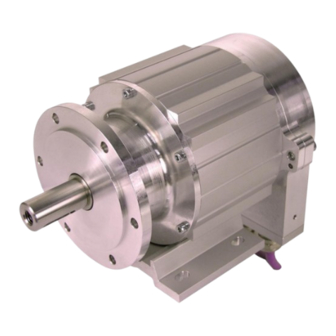
- Page 2 Original Seite 2 - 26 TR-Explosionsschutzgehäuse Page 27 - 52 Explosionsschutzgehäuse mit eingebautem Mess-System Explosionsschutzgehäuse - Typ _A*V115* AEV-115 Abbildungen ähnlich Stock photos ADV-115 II 3D Ex tc IIIC T_ Dc IP65 Date of manufacture: DD.MM.YYYY _Grundlegende Sicherheitshinweise _Verwendungszweck _Produktbeschreibung _Allgemeine technische Daten _Explosionsschutz Kenndaten _Montage...
- Page 3 Courier-Schrift zeigt Text an, der auf dem Display bzw. Bildschirm sichtbar ist und Menüauswahlen von Software. < > weist auf Tasten der Tastatur Ihres Computers hin (wie etwa <RETURN>). TR-Electronic GmbH 2016, All Rights Reserved Printed in the Federal Republic of Germany Page 2 of 52 TR-ECE-BA-DGB-0124-04...
-
Page 4: Table Of Contents
5.1 Sicherheitsgerichtete Anwendungen ..................20 5.2 NICHT-sicherheitsgerichtete Anwendungen ................21 6 Potenzialausgleichsleitung – Anschluss ..................22 7 Entsorgung ............................22 TR-Electronic GmbH 2016, All Rights Reserved Printed in the Federal Republic of Germany 03/02/2022 TR-ECE-BA-DGB-0124-04 Page 3 of 52... -
Page 5: Inhaltsverzeichnis
8.1 Technische Unterlagen zur Artikel-Nummer ................23 8.2 Schnittstellen-spezifische Benutzerhandbücher ..............23 9 EU-Konformitätserklärung ......................24 9.1 A_V115 ........................... 24 9.2 ADV115 + FS .......................... 25 TR-Electronic GmbH 2016, All Rights Reserved Printed in the Federal Republic of Germany Page 4 of 52 TR-ECE-BA-DGB-0124-04 03/02/2022... -
Page 6: Änderungs-Index
25.04.2016 Anpassung der Temperaturangabe 19.02.2018 Konformitätserklärung aktualisiert 20.08.2020 Hinweise für den Einsatz in sicherheitsgerichteten Anwendungen 18.11.2020 Aktualisierung der Konformitätserklärung 02.03.2022 TR-Electronic GmbH 2016, All Rights Reserved Printed in the Federal Republic of Germany 03/02/2022 TR-ECE-BA-DGB-0124-04 Page 5 of 52... -
Page 7: Allgemeines
Redundante Abtastung Optische Abtastung 15 Bit Vollwelle Außendurchmesser in mm Absolut, Singleturn Absolut, Multiturn Fortlaufende Nummer * = Platzhalter TR-Electronic GmbH 2016, All Rights Reserved Printed in the Federal Republic of Germany Page 6 of 52 TR-ECE-BA-DGB-0124-04 03/02/2022... -
Page 8: Geltungsbereich
Projektierung, Auswahl und Errichtung elektrischer Anlagen Explosionsfähige Atmosphäre: Geräte - EN 60079-31 Staubexplosionsschutz durch Gehäuse "t" DIN EN 60529 Schutzarten durch Gehäuse (IP-Code) TR-Electronic GmbH 2016, All Rights Reserved Printed in the Federal Republic of Germany 03/02/2022 TR-ECE-BA-DGB-0124-04 Page 7 of 52... -
Page 9: Verwendete Abkürzungen / Begriffe
Mess-System der Baureihe 115. Der Aufbau, sowie das Zusammenwirken der einzelnen Komponenten und des Gehäuses hinsichtlich ihrer Einsatzfähigkeit in explosionsgefährdeten Bereichen, werden von der Firma TR-Electronic GmbH geprüft und durch die Kennzeichnung mit dem Typenschild bestätigt. TR-Electronic GmbH 2016, All Rights Reserved... -
Page 10: Grundlegende Sicherheitshinweise
Informationen bzw. Merkmale und Anwendungstipps des verwendeten Produkts. bedeutet, dass entsprechende ESD-Schutzmaßnahmen nach DIN EN 61340-5-1 Beiblatt 1 zu beachten sind. TR-Electronic GmbH 2016, All Rights Reserved Printed in the Federal Republic of Germany 03/02/2022 TR-ECE-BA-DGB-0124-04 Page 9 of 52... -
Page 11: Verpflichtung Des Betreibers Vor Der Inbetriebnahme
Zustand durchgeführt werden. Bei Defekten darf das Betriebsmittel nicht betrieben werden, es darf grundsätzlich nicht geöffnet werden und Staubablagerungen > 5 mm müssen beseitigt werden. TR-Electronic GmbH 2016, All Rights Reserved Printed in the Federal Republic of Germany Page 10 of 52... -
Page 12: Bestimmungsgemäße Verwendung
In Umgebungen mit explosiver Atmosphäre der Zonen 0, 1, 2, 20 und 21 zu medizinischen Zwecken die Inbetriebnahme des Betriebsmittels, wenn das Typenschild nicht mehr lesbar ist oder gänzlich fehlt. TR-Electronic GmbH 2016, All Rights Reserved Printed in the Federal Republic of Germany 03/02/2022 TR-ECE-BA-DGB-0124-04... -
Page 13: Einsatz In Sicherheitsgerichteten Anwendungen
Montage berücksichtigt werden. Generell sind für den An- bau die Auflagen und Abnahmebedingungen der Gesamtanlage zu berücksichtigen. TR-Electronic GmbH 2016, All Rights Reserved Printed in the Federal Republic of Germany Page 12 of 52... -
Page 14: Gewährleistung Und Haftung
-Benutzerhandbuch ausdrücklich beschriebenen, vornehmen. Reparaturen dürfen nur vom Hersteller, oder einer vom Hersteller autorisierten Stelle bzw. Person vorgenommen werden. TR-Electronic GmbH 2016, All Rights Reserved Printed in the Federal Republic of Germany 03/02/2022 TR-ECE-BA-DGB-0124-04 Page 13 of 52... -
Page 15: Personalauswahl Und -Qualifikation; Grundsätzliche Pflichten
„ausführenden Personals“, ist zusätzlich die Norm IEC 60079-17 bzw. DIN EN 60079-17 einzusehen (Bezugsquellen z.B. Beuth Verlag GmbH, VDE-Verlag GmbH). TR-Electronic GmbH 2016, All Rights Reserved Printed in the Federal Republic of Germany Page 14 of 52 TR-ECE-BA-DGB-0124-04... -
Page 16: Erstinbetriebnahme / Inbetriebnahme
Keine Schweißarbeiten vornehmen, wenn das Betriebsmittel bereits verdrahtet bzw. eingeschaltet ist. Berührungen der Betriebsmittel-Anschlusskontakte mit den Fingern sind zu vermeiden, bzw. sind die entsprechenden ESD-Schutzmaßnahmen anzuwenden. TR-Electronic GmbH 2016, All Rights Reserved Printed in the Federal Republic of Germany 03/02/2022 TR-ECE-BA-DGB-0124-04... -
Page 17: Prüfung, Wartung Und Instandhaltung
Nicht benötigte Kabelverschraubungen für Kabeleinführungen müssen durch entsprechend für die verwendete Gerätekategorie bescheinigte Verschlusselemente verschlossen werden. Montageanweisungen Sicherheitshinweise Herstellers Komponenten sind zu beachten. TR-Electronic GmbH 2016, All Rights Reserved Printed in the Federal Republic of Germany Page 16 of 52 TR-ECE-BA-DGB-0124-04 03/02/2022... -
Page 18: Transport / Lagerung
Nur Original Verpackung verwenden! Unsachgemäßes Verpackungsmaterial kann beim Transport Schäden am Gerät verursachen. Lagerung Lagertemperatur : -40 bis +80 °C Trocken lagern TR-Electronic GmbH 2016, All Rights Reserved Printed in the Federal Republic of Germany 03/02/2022 TR-ECE-BA-DGB-0124-04 Page 17 of 52... -
Page 19: Allgemeine Technische Daten
Al Mg Si 0.5 F25 RW Flanschwerkstoff ............. EN AW-AlCu6BiPb Welle, Edelstahl ............ WN 1.4305, korrosionsbeständig * Hinweise beachten, siehe Kapitel 2.13 auf Seite 16 TR-Electronic GmbH 2016, All Rights Reserved Printed in the Federal Republic of Germany Page 18 of 52 TR-ECE-BA-DGB-0124-04 03/02/2022... -
Page 20: Explosionsschutz Kenndaten
Sicherheit bei normalem Betrieb * Schutzart ............. IP65: Schutzarten durch Gehäuse nach DIN EN 60529 * Hinweise beachten, siehe Kapitel 2.13 auf Seite 16 TR-Electronic GmbH 2016, All Rights Reserved Printed in the Federal Republic of Germany 03/02/2022 TR-ECE-BA-DGB-0124-04... -
Page 21: Montage
Toleranzangaben des Kupplung-Herstellers sind zu berücksichtigen 5.1 Sicherheitsgerichtete Anwendungen Montage sicherheitsgerichteten Anwendungen gemäß Sicherheitshandbuch vorzunehmen, siehe Kapitel „Einsatz in sicherheitsgerichteten Anwendungen“ auf Seite 12. TR-Electronic GmbH 2016, All Rights Reserved Printed in the Federal Republic of Germany Page 20 of 52 TR-ECE-BA-DGB-0124-04 03/02/2022... -
Page 22: Nicht-Sicherheitsgerichtete Anwendungen
: Zentrierbund, Passung j6 : Montage-Fuß, in 90°-Schritten verdrehbar : ATEX-konforme Kupplung : Anschluss-Haube, werkseitig um 180° verdrehbar Abbildung 1: Montageschema TR-Electronic GmbH 2016, All Rights Reserved Printed in the Federal Republic of Germany 03/02/2022 TR-ECE-BA-DGB-0124-04 Page 21 of 52... -
Page 23: Potenzialausgleichsleitung - Anschluss
Abbildung 3: Potenzialausgleichsleitung – Anschluss, Variante mit Stecker 7 Entsorgung Elektronik-Schrott ist Sondermüll. Zur Entsorgung sind die jeweils geltenden landesspezifischen Vorschriften zu beachten. TR-Electronic GmbH 2016, All Rights Reserved Printed in the Federal Republic of Germany Page 22 of 52 TR-ECE-BA-DGB-0124-04... -
Page 24: Download
Absolut Encoder Serie CEV-115 mit PROFIBUS-DP Schnittstelle TR-ECE-BA-DGB-0064 Absolut Encoder Serie CDV-115 mit PROFIBUS-DP Schnittstelle Absolut Encoder Serie CDx-75 mit PROFIBUS-DP Schnittstelle TR-ECE-BA-D-0092 und PROFIsafe Profil TR-Electronic GmbH 2016, All Rights Reserved Printed in the Federal Republic of Germany 03/02/2022 TR-ECE-BA-DGB-0124-04 Page 23 of 52... -
Page 25: Eu-Konformitätserklärung
EU-Konformitätserklärung 9 EU-Konformitätserklärung 9.1 A_V115 TR-Electronic GmbH 2016, All Rights Reserved Printed in the Federal Republic of Germany Page 24 of 52 TR-ECE-BA-DGB-0124-04 03/02/2022... -
Page 26: Adv115 + Fs
9.2 ADV115 + FS TR-Electronic GmbH 2016, All Rights Reserved Printed in the Federal Republic of Germany 03/02/2022 TR-ECE-BA-DGB-0124-04 Page 25 of 52... - Page 27 EU-Konformitätserklärung TR-Electronic GmbH 2016, All Rights Reserved Printed in the Federal Republic of Germany Page 26 of 52 TR-ECE-BA-DGB-0124-04 03/02/2022...
- Page 28 Date of manufacture: DD.MM.YYYY _Basic safety instructions _Intended use _Product description _General technical data User Manual _Explosion protection characteristics _Assembly TR-Electronic GmbH 2016, All Rights Reserved Printed in the Federal Republic of Germany 03/02/2022 TR-ECE-BA-DGB-0124-04 Page 27 of 52...
- Page 29 Courier-text shows text which is visible on the display or screen as well as software menu-selections. < > refers to keys on your computer keyboard (e.g. <RETURN>). TR-Electronic GmbH 2016, All Rights Reserved Printed in the Federal Republic of Germany Page 28 of 52 TR-ECE-BA-DGB-0124-04 03/02/2022...
- Page 30 5.1 Safety-related applications ..................... 46 5.2 NON safety-related applications ..................... 47 6 Equipotential bonding conductor - Connection ................48 7 Disposal ............................48 TR-Electronic GmbH 2016, All Rights Reserved Printed in the Federal Republic of Germany 03/02/2022 TR-ECE-BA-DGB-0124-04 Page 29 of 52...
-
Page 31: Table Of Contents
8.2 Interface-specific user manual ....................49 9 EU declaration of conformity ......................50 9.1 A_V115 ........................... 50 9.2 ADV115 + FS .......................... 51 TR-Electronic GmbH 2016, All Rights Reserved Printed in the Federal Republic of Germany Page 30 of 52 TR-ECE-BA-DGB-0124-04... -
Page 32: Amendment-Index
02/19/2018 08/20/2020 Declaration of conformity updated 11/18/2020 Notes for the usage in safety-related applications 03/02/2022 Updating the declaration of conformity TR-Electronic GmbH 2016, All Rights Reserved Printed in the Federal Republic of Germany 03/02/2022 TR-ECE-BA-DGB-0124-04 Page 31 of 52... -
Page 33: General
Optical scanning unit 15 bit Solid shaft External diameter in mm Absolute, single turn Absolute, multi turn Consecutive number * = Wild cards TR-Electronic GmbH 2016, All Rights Reserved Printed in the Federal Republic of Germany Page 32 of 52 TR-ECE-BA-DGB-0124-04 03/02/2022... -
Page 34: Scope
EN 60079-31 Equipment dust ignition protection by enclosure "t" Degrees of protection provided by DIN EN 60529 enclosures (IP code) TR-Electronic GmbH 2016, All Rights Reserved Printed in the Federal Republic of Germany 03/02/2022 TR-ECE-BA-DGB-0124-04 Page 33 of 52... -
Page 35: Used Abbreviations / Terms
The construction, as well as the interaction of the individual components and the housing with regards to their possibilities for use in potentially explosive areas, are tested by the company TR-Electronic GmbH and confirmed by identification with the nameplate. TR-Electronic GmbH 2016, All Rights Reserved... -
Page 36: Basic Safety Instructions
ESD-safety measures according to DIN EN 61340-5-1 supplement 1 are to be observed. TR-Electronic GmbH 2016, All Rights Reserved Printed in the Federal Republic of Germany 03/02/2022 TR-ECE-BA-DGB-0124-04... -
Page 37: Obligation Of The Operator Prior To Commissioning
The equipment may not be used in case of defects, as a basic principle it may not be opened and dust deposits > 5 mm must be removed. TR-Electronic GmbH 2016, All Rights Reserved Printed in the Federal Republic of Germany... -
Page 38: Intended Use
0, 1, 2, 20 and 21 for medical aims commissioning of the equipment if the nameplate is no longer readable or is completely missing. TR-Electronic GmbH 2016, All Rights Reserved Printed in the Federal Republic of Germany 03/02/2022 TR-ECE-BA-DGB-0124-04... -
Page 39: Usage In Safety-Related Applications
In general, the requirements and acceptance conditions for the complete system must be taken into account for mounting. TR-Electronic GmbH 2016, All Rights Reserved Printed in the Federal Republic of Germany Page 38 of 52... -
Page 40: Warranty And Liability
2.7 Warranty and liability The "General terms and conditions" (“Allgemeine Geschäftsbedingungen”) of the company TR-Electronic GmbH apply in general. This will be available to the operator with the contract confirmation or –conclusion at the latest. Warranty- or liability claims with regards to personal- and property damage are excluded, if they are the result of one or more of the following causes: ... -
Page 41: Personnel Selection And -Qualification; Basic Obligations
"expert person with leadership functions" and the "performing personnel", the IEC 60079-17 or DIN EN 60079-17 standards are to be additionally consulted [suppliers e.g. Beuth Verlag GmbH, VDE-Verlag GmbH]. TR-Electronic GmbH 2016, All Rights Reserved Printed in the Federal Republic of Germany Page 40 of 52... -
Page 42: First Commissioning / Commissioning
Do not perform any welding work once the equipment has already been wired and switched on. Touching the equipment-connection contacts with bare hands is to be avoided, or the respective ESD-protective measures are to be implemented. TR-Electronic GmbH 2016, All Rights Reserved Printed in the Federal Republic of Germany 03/02/2022 TR-ECE-BA-DGB-0124-04... -
Page 43: Inspection, Maintenance And Repair
The component manufacturer's assembly and safety instructions must be complied with. TR-Electronic GmbH 2016, All Rights Reserved Printed in the Federal Republic of Germany Page 42 of 52 TR-ECE-BA-DGB-0124-04... -
Page 44: Transport / Storage
Inappropriate packaging material may cause damage to the device during transport. Storage Storage temperature: -40 to +80 °C Store in a dry place TR-Electronic GmbH 2016, All Rights Reserved Printed in the Federal Republic of Germany 03/02/2022 TR-ECE-BA-DGB-0124-04 Page 43 of 52... -
Page 45: General Technical Data
Flange material ............EN AW-AlCu6BiPb Shaft, stainless steel ..........WN 1.4305, corrosion resistant * Observe instructions, see chapter 2.13 on page 42 TR-Electronic GmbH 2016, All Rights Reserved Printed in the Federal Republic of Germany Page 44 of 52 TR-ECE-BA-DGB-0124-04 03/02/2022... -
Page 46: Explosion Protection Characteristics
* Protection class ..........IP65: Degrees of protection provided by enclosures according to DIN EN 60529 * Observe instructions, see chapter 2.13 on page 42 TR-Electronic GmbH 2016, All Rights Reserved Printed in the Federal Republic of Germany 03/02/2022 TR-ECE-BA-DGB-0124-04... -
Page 47: Assembly
The assembly in safety-related applications is to be made in accordance with the Safety Manual, see chapter “Usage in safety-related applications” on page 38. TR-Electronic GmbH 2016, All Rights Reserved Printed in the Federal Republic of Germany Page 46 of 52... -
Page 48: Non Safety-Related Applications
: Mounting plate, can be rotated in steps of 90° : ATEX-conformant coupling : Connector hood, can be rotated around 180° (factory only) Figure 1: Mounting schema TR-Electronic GmbH 2016, All Rights Reserved Printed in the Federal Republic of Germany 03/02/2022 TR-ECE-BA-DGB-0124-04... -
Page 49: Equipotential Bonding Conductor - Connection
Figure 3: Equipotential bonding conductor, variant with connectors 7 Disposal Electronic waste is hazardous waste. The applicable country-specific regulations are to be adhered to for disposal. TR-Electronic GmbH 2016, All Rights Reserved Printed in the Federal Republic of Germany Page 48 of 52 TR-ECE-BA-DGB-0124-04... -
Page 50: Download
Absolute Encoder Series CEV-115 with PROFIBUS-DP interface TR-ECE-BA-DGB-0064 Absolute Encoder Series CDV-115 with PROFIBUS-DP interface Absolute Encoder Series CDx-75 with PROFIBUS-DP interface TR-ECE-BA-GB-0092 and PROFIsafe profile TR-Electronic GmbH 2016, All Rights Reserved Printed in the Federal Republic of Germany 03/02/2022 TR-ECE-BA-DGB-0124-04 Page 49 of 52... -
Page 51: Eu Declaration Of Conformity
EU declaration of conformity 9 EU declaration of conformity 9.1 A_V115 TR-Electronic GmbH 2016, All Rights Reserved Printed in the Federal Republic of Germany Page 50 of 52 TR-ECE-BA-DGB-0124-04 03/02/2022... -
Page 52: Adv115 + Fs
9.2 ADV115 + FS TR-Electronic GmbH 2016, All Rights Reserved Printed in the Federal Republic of Germany 03/02/2022 TR-ECE-BA-DGB-0124-04 Page 51 of 52... - Page 53 EU declaration of conformity TR-Electronic GmbH 2016, All Rights Reserved Printed in the Federal Republic of Germany Page 52 of 52 TR-ECE-BA-DGB-0124-04 03/02/2022...
- Page 54 Seite 2 - 68 Page 69 - 136 +SSI Absolute Encoder CEV-115 Explosion Protection Enclosure Explosionsschutzgehäuse / _AEV115M Abbildung ähnlich Stock photo _Zusätzliche Sicherheitshinweise _Installation _Inbetriebnahme _Parametrierung _Fehlerursachen und Abhilfen _Additional safety instructions _Installation _Commissioning _Parameterization _Cause of faults and remedies Benutzerhandbuch User Manual 4376AA...
- Page 55 PROFIBUS-DP und das PROFIBUS-Logo sind eingetragene Warenzeichen der PROFIBUS Nutzerorganisation e.V. (PNO) SIMATIC ist ein eingetragenes Warenzeichen der SIEMENS AG TR-Electronic GmbH 2013, All Rights Reserved Printed in the Federal Republic of Germany Page 2 of 136 TR - ECE - BA - DGB - 0104 - 07...
- Page 56 6.2 PNO CLASS 1 16-Bit ......................28 6.3 PNO CLASS 1 32-Bit ......................29 6.4 PNO CLASS 2 16-Bit ......................30 TR-Electronic GmbH 2013, All Rights Reserved Printed in the Federal Republic of Germany 11/07/2018 TR - ECE - BA - DGB - 0104 - 07...
-
Page 57: Inhaltsverzeichnis
7.2.2.17 Seriennummer ......................... 67 7.2.2.18 Herstellerspezifische Diagnosen ..................... 68 7.3 Sonstige Störungen ........................ 68 TR-Electronic GmbH 2013, All Rights Reserved Printed in the Federal Republic of Germany Page 4 of 136 TR - ECE - BA - DGB - 0104 - 07... -
Page 58: Änderungs-Index
- Technische Daten entfernt Produktbild aktualisiert 09.03.17 LED-Verhalten angepasst 07.11.18 TR-Electronic GmbH 2013, All Rights Reserved Printed in the Federal Republic of Germany 11/07/2018 TR - ECE - BA - DGB - 0104 - 07 Page 5 of 136... -
Page 59: Allgemeines
Kapitel „Mitgeltende Dokumente“ in der Montageanleitung www.tr-electronic.de/f/TR-ECE-BA-DGB-0125 • optional: -Benutzerhandbuch mit Montageanleitung TR-Electronic GmbH 2013, All Rights Reserved Printed in the Federal Republic of Germany Page 6 of 136 TR - ECE - BA - DGB - 0104 - 07 11/07/2018... -
Page 60: Verwendete Abkürzungen / Begriffe
Dezentralized Periphery (Dezentrale Peripherie) Elektro-Magnetische-Verträglichkeit Geräte-Stammdaten-Datei PROFIBUS Nutzerorganisation e.V. PROFIBUS herstellerunabhängiger, offener Feldbusstandard TR-Electronic GmbH 2013, All Rights Reserved Printed in the Federal Republic of Germany 11/07/2018 TR - ECE - BA - DGB - 0104 - 07 Page 7 of 136... -
Page 61: Zusätzliche Sicherheitshinweise
Beachten der Montageanleitung, insbesondere das dort enthaltene Kapitel "Grundlegende Sicherheitshinweise" muss vor Arbeitsbeginn gelesen und verstanden worden sein TR-Electronic GmbH 2013, All Rights Reserved Printed in the Federal Republic of Germany Page 8 of 136 TR - ECE - BA - DGB - 0104 - 07... -
Page 62: Organisatorische Maßnahmen
Der gefahrlose Einsatz erfordert zusätzliche Maßnahmen bzw. Anforderungen. Diese sind vor der Erstinbetriebnahme zu erfassen und müssen entsprechend umgesetzt werden. TR-Electronic GmbH 2013, All Rights Reserved Printed in the Federal Republic of Germany 11/07/2018 TR - ECE - BA - DGB - 0104 - 07... -
Page 63: Schnittstellen Informationen
Datenaustausch in der Feldebene konzipiert ist. Die Grundfunktionalität wird durch die Leistungsstufe V0 festgelegt. Dazu gehören der zyklische Datenaustausch sowie die stations-, modul- und kanalspezifische Diagnose. TR-Electronic GmbH 2013, All Rights Reserved Printed in the Federal Republic of Germany Page 10 of 136... -
Page 64: Ssi
N.C. SSI-Clock- 65Ω Abbildung 1: SSI Prinzip-Eingangsschaltung Abbildung 2: SSI-Ausgangsschaltung TR-Electronic GmbH 2013, All Rights Reserved Printed in the Federal Republic of Germany 11/07/2018 TR - ECE - BA - DGB - 0104 - 07 Page 11 of 136... -
Page 65: Installation / Inbetriebnahmevorbereitung
PROFIBUS Inbetriebnahmerichtlinie, PNO Bestell-Nr.: 8.031 und die darin referenzierten Normen und PNO Dokumente zu beachten! Insbesondere ist die EMV-Richtlinie in der gültigen Fassung zu beachten! TR-Electronic GmbH 2013, All Rights Reserved Printed in the Federal Republic of Germany Page 12 of 136... -
Page 66: Bus-Terminierung
Stationsadresse läuft das Gerät nicht an, LEDs = AUS. TR-Electronic GmbH 2013, All Rights Reserved Printed in the Federal Republic of Germany 11/07/2018 TR - ECE - BA - DGB - 0104 - 07 Page 13 of 136... -
Page 67: Ssi - Schnittstelle
● Es wird empfohlen, nach Abschluss der Montagearbeiten eine visuelle Abnahme mit Protokoll zu erstellen. TR-Electronic GmbH 2013, All Rights Reserved Printed in the Federal Republic of Germany Page 14 of 136 TR - ECE - BA - DGB - 0104 - 07... -
Page 68: Rs422 Übertragungstechnik
RS422-Sender stellen unter Last Ausgangspegel von ± 2 V zwischen den beiden Ausgängen zur Verfügung, die Empfängerbausteine erkennen Pegel von ± 200 mV noch als gültiges Signal. TR-Electronic GmbH 2013, All Rights Reserved Printed in the Federal Republic of Germany 11/07/2018... -
Page 69: Kabelspezifikation
50 ca. 100 ca. 200 ca. 400 ca. 500 TR-Electronic GmbH 2013, All Rights Reserved Printed in the Federal Republic of Germany Page 16 of 136 TR - ECE - BA - DGB - 0104 - 07 11/07/2018... -
Page 70: Datenübertragung
Takt+ High Daten+ High intern re-triggerbares Monoflop Abbildung 4: SSI-Übertragungsformat TR-Electronic GmbH 2013, All Rights Reserved Printed in the Federal Republic of Germany 11/07/2018 TR - ECE - BA - DGB - 0104 - 07 Page 17 of 136... -
Page 71: Anschluss
Für die Versorgungen sind jeweils paarweise verdrillte und geschirmte Kabel mit einem Mindestquerschnitt von 0,5 mm zu verwenden ! TR-Electronic GmbH 2013, All Rights Reserved Printed in the Federal Republic of Germany Page 18 of 136 TR - ECE - BA - DGB - 0104 - 07... - Page 72 RS485–_IN/OUT, TRWinProg Pin 2 RS485+_IN/OUT, TRWinProg Nur zum Nachladen der Firmware ! TR-Electronic GmbH 2013, All Rights Reserved Printed in the Federal Republic of Germany 11/07/2018 TR - ECE - BA - DGB - 0104 - 07 Page 19 of 136...
-
Page 73: Schirmauflage
6. Dichteinsatz / Kontakthülse (2) + (3) in Einschraubstutzen (5) bündig zusammen stecken. 7. Überwurfmutter (1) mit Einschraubstutzen (5) verschrauben. TR-Electronic GmbH 2013, All Rights Reserved Printed in the Federal Republic of Germany Page 20 of 136 TR - ECE - BA - DGB - 0104 - 07... - Page 74 Einschraubstutzen vorgesehenen Längsnuten passen. 7. Überwurfmutter (1) mit Einschraubstutzen (4) verschrauben. TR-Electronic GmbH 2013, All Rights Reserved Printed in the Federal Republic of Germany 11/07/2018 TR - ECE - BA - DGB - 0104 - 07 Page 21 of 136...
-
Page 75: Inbetriebnahme
Projektierungsfehlern erreicht. Das Mess-System hat die PNO-Identnummer AAAB (Hex). Diese Nummer ist reserviert und bei der PNO hinterlegt. TR-Electronic GmbH 2013, All Rights Reserved Printed in the Federal Republic of Germany Page 22 of 136 TR - ECE - BA - DGB - 0104 - 07... -
Page 76: Anlauf Am Profibus
Inputs zurückgeben WCFG = Wait Configuration DXCHG = Data Exchange Abbildung 6: DP-Slave Initialisierung TR-Electronic GmbH 2013, All Rights Reserved Printed in the Federal Republic of Germany 11/07/2018 TR - ECE - BA - DGB - 0104 - 07... -
Page 77: Bus-Statusanzeige
Fehler, Bus im Zyklus Entsprechende Maßnahmen im Fehlerfall siehe Kapitel „Optische Anzeigen, LEDs“, Seite 60. TR-Electronic GmbH 2013, All Rights Reserved Printed in the Federal Republic of Germany Page 24 of 136 TR - ECE - BA - DGB - 0104 - 07... -
Page 78: Parametrierung Und Konfiguration
Oberflächen zur Verfügung. Die Bit- bzw. Byte-Lage wird dabei im "Hintergrund" automatisch gemanagt. Das Konfigurationsbeispiel Seite 56 verdeutlicht dies noch mal. TR-Electronic GmbH 2013, All Rights Reserved Printed in the Federal Republic of Germany 11/07/2018 TR - ECE - BA - DGB - 0104 - 07... - Page 79 0 = Konsistenz über ein Byte oder Wort Konsistenz: 1 = Konsistenz über das ganze Modul TR-Electronic GmbH 2013, All Rights Reserved Printed in the Federal Republic of Germany Page 26 of 136 TR - ECE - BA - DGB - 0104 - 07...
-
Page 80: Übersicht
Endschalter - Endschalter Geschwindigkeits-Ausgabe - Geschwindigkeit aus Sicht des Bus-Masters TR-Electronic GmbH 2013, All Rights Reserved Printed in the Federal Republic of Germany 11/07/2018 TR - ECE - BA - DGB - 0104 - 07 Page 27 of 136... -
Page 81: Pno Class 1 16-Bit
Uhrzeiger- werte gegen den Uhr- sinn drehend zeigersinn drehend TR-Electronic GmbH 2013, All Rights Reserved Printed in the Federal Republic of Germany Page 28 of 136 TR - ECE - BA - DGB - 0104 - 07... -
Page 82: Pno Class 1 32-Bit
Uhrzeiger- werte gegen den Uhr- sinn drehend zeigersinn drehend TR-Electronic GmbH 2013, All Rights Reserved Printed in the Federal Republic of Germany 11/07/2018 TR - ECE - BA - DGB - 0104 - 07 Page 29 of 136... -
Page 83: Pno Class 2 16-Bit
5 – 4 3 – 0 Data Konsistenz Wort Format Eingangsdaten Längen-Code TR-Electronic GmbH 2013, All Rights Reserved Printed in the Federal Republic of Germany Page 30 of 136 TR - ECE - BA - DGB - 0104 - 07 11/07/2018... - Page 84 – 2 – 2 Default (dez.) 16777216 Messlänge in Schritten TR-Electronic GmbH 2013, All Rights Reserved Printed in the Federal Republic of Germany 11/07/2018 TR - ECE - BA - DGB - 0104 - 07 Page 31 of 136...
-
Page 85: Pno Class 2 32-Bit
5 – 4 3 – 0 Data Konsistenz Wort Format Eingangsdaten Längen-Code TR-Electronic GmbH 2013, All Rights Reserved Printed in the Federal Republic of Germany Page 32 of 136 TR - ECE - BA - DGB - 0104 - 07 11/07/2018... - Page 86 – 2 – 2 Default (dez.) 16777216 Messlänge in Schritten TR-Electronic GmbH 2013, All Rights Reserved Printed in the Federal Republic of Germany 11/07/2018 TR - ECE - BA - DGB - 0104 - 07 Page 33 of 136...
-
Page 87: Tr-Mode Position
5 – 4 3 – 0 Data Konsistenz Wort Format Eingangsdaten Längen-Code TR-Electronic GmbH 2013, All Rights Reserved Printed in the Federal Republic of Germany Page 34 of 136 TR - ECE - BA - DGB - 0104 - 07 11/07/2018... - Page 88 Uhrzeigersinn drehend zeigersinn drehend Kurze Diagnose Nein Diagnose Meldemodus ausgeschaltet eingeschaltet TR-Electronic GmbH 2013, All Rights Reserved Printed in the Federal Republic of Germany 11/07/2018 TR - ECE - BA - DGB - 0104 - 07 Page 35 of 136...
- Page 89 7 – 0 Data – 2 – 2 Default (dez.) Umdrehungen Nenner TR-Electronic GmbH 2013, All Rights Reserved Printed in the Federal Republic of Germany Page 36 of 136 TR - ECE - BA - DGB - 0104 - 07 11/07/2018...
- Page 90 – 2 – 2 – 2 Default (dez.) Preset 2 TR-Electronic GmbH 2013, All Rights Reserved Printed in the Federal Republic of Germany 11/07/2018 TR - ECE - BA - DGB - 0104 - 07 Page 37 of 136...
- Page 91 Byte 7 – 0 Data – 2 Default (dez.) TR-Electronic GmbH 2013, All Rights Reserved Printed in the Federal Republic of Germany Page 38 of 136 TR - ECE - BA - DGB - 0104 - 07 11/07/2018...
-
Page 92: Tr-Mode Position + Velocity (Geschwindigkeit)
5 – 4 3 – 0 Data Konsistenz Wort Format Eingangsdaten Längen-Code TR-Electronic GmbH 2013, All Rights Reserved Printed in the Federal Republic of Germany 11/07/2018 TR - ECE - BA - DGB - 0104 - 07 Page 39 of 136... - Page 93 Uhrzeigersinn drehend zeigersinn drehend Kurze Diagnose Nein Diagnose Meldemodus ausgeschaltet eingeschaltet TR-Electronic GmbH 2013, All Rights Reserved Printed in the Federal Republic of Germany Page 40 of 136 TR - ECE - BA - DGB - 0104 - 07 11/07/2018...
- Page 94 7 – 0 Data – 2 – 2 Default (dez.) Umdrehungen Nenner TR-Electronic GmbH 2013, All Rights Reserved Printed in the Federal Republic of Germany 11/07/2018 TR - ECE - BA - DGB - 0104 - 07 Page 41 of 136...
- Page 95 – 2 – 2 – 2 Default (dez.) Preset 2 TR-Electronic GmbH 2013, All Rights Reserved Printed in the Federal Republic of Germany Page 42 of 136 TR - ECE - BA - DGB - 0104 - 07 11/07/2018...
- Page 96 Byte 7 – 0 Data – 2 Default (dez.) TR-Electronic GmbH 2013, All Rights Reserved Printed in the Federal Republic of Germany 11/07/2018 TR - ECE - BA - DGB - 0104 - 07 Page 43 of 136...
-
Page 97: Preset-Justage-Funktion
Gesamtmesslänge in Schritten – 1, Obergrenze innerhalb von ≤ 33 554 432 TR-Electronic GmbH 2013, All Rights Reserved Printed in the Federal Republic of Germany Page 44 of 136 TR - ECE - BA - DGB - 0104 - 07... -
Page 98: Beschreibung Der Betriebsparameter
Wertesprünge > 1 Umdrehung) einen "Diagnosealarm" (OB82 bei SIMATIC auslöst, siehe auch Kapitel "Alarme", Seite 64. TR-Electronic GmbH 2013, All Rights Reserved Printed in the Federal Republic of Germany 11/07/2018 TR - ECE - BA - DGB - 0104 - 07... -
Page 99: Inbetriebnahmefunktion
– 2 – 2 – 2 – 2 Steuerbits Preset-Justagewert TR-Electronic GmbH 2013, All Rights Reserved Printed in the Federal Republic of Germany Page 46 of 136 TR - ECE - BA - DGB - 0104 - 07 11/07/2018... - Page 100 Teach-In Start wird nicht unterstützt! keine Justage Justage Anforderung Justage ausführen TR-Electronic GmbH 2013, All Rights Reserved Printed in the Federal Republic of Germany 11/07/2018 TR - ECE - BA - DGB - 0104 - 07 Page 47 of 136...
-
Page 101: Kurze Diagnose
Mit diesem Parameter kann die Anzahl der Diagnosebytes von 6+51 Bytes auf 6+10 Bytes begrenzt werden, damit das Mess-System auch an PROFIBUS-Mastern mit älteren Ausgabeständen betrieben werden kann. TR-Electronic GmbH 2013, All Rights Reserved Printed in the Federal Republic of Germany Page 48 of 136... -
Page 102: Skalierungsfunktion
Messlänge in Schritten = Schritte pro Umdrehung * Anzahl der Umdrehungen Zur Berechnung können die Parameter Schritte/Umdr. und Anzahl Umdrehungen vom Typenschild des Mess-Systems abgelesen werden. TR-Electronic GmbH 2013, All Rights Reserved Printed in the Federal Republic of Germany 11/07/2018... - Page 103 Richtung fahren, zwangsläufig zu Verschiebungen. Für derartige Anwendungen ist stets eine der TR-Konfigurationen "TR-Mode Position" bzw. "TR-Mode Position+Velocity" zu verwenden. TR-Electronic GmbH 2013, All Rights Reserved Printed in the Federal Republic of Germany Page 50 of 136 TR - ECE - BA - DGB - 0104 - 07...
-
Page 104: Skalierungsparameter Tr-Modes "Position" + "Velocity
Messlänge in Schritten = Schritte pro Umdrehung * Anzahl der Umdrehungen Zur Berechnung können die Parameter Schritte/Umdr. und Anzahl Umdrehungen vom Typenschild des Mess-Systems abgelesen werden. TR-Electronic GmbH 2013, All Rights Reserved Printed in the Federal Republic of Germany 11/07/2018... -
Page 105: Umdrehungen Zähler / Umdrehungen Nenner
Mess-System bei einer geringfügigen Überschreitung des Verfahrweges keinen Istwertsprung (Nullübergang) erzeugt. Der Einfachheit halber kann auch der volle Umdrehungsbereich des Mess-Systems programmiert werden. TR-Electronic GmbH 2013, All Rights Reserved Printed in the Federal Republic of Germany Page 52 of 136... - Page 106 4096 Umdrehungen Zähler = 1348,073499 Schritte / Umdr. * 1 Umdrehung Nenner = 5521709 Schritte (abgerundet) TR-Electronic GmbH 2013, All Rights Reserved Printed in the Federal Republic of Germany 11/07/2018 TR - ECE - BA - DGB - 0104 - 07...
-
Page 107: Code Ssi-Schnittstelle
≤ 33 554 432 Default Preset 1 = 0, Preset 2 = 1 TR-Electronic GmbH 2013, All Rights Reserved Printed in the Federal Republic of Germany Page 54 of 136 TR - ECE - BA - DGB - 0104 - 07... -
Page 108: Unterer Endschalter / Oberer Endschalter
Seite 39 Mit diesem Parameter kann die Angabe der Umdrehungsgeschwindigkeit in beliebigen Schritten zwischen 1/1 und 1/100 U/min skaliert werden. TR-Electronic GmbH 2013, All Rights Reserved Printed in the Federal Republic of Germany 11/07/2018 TR - ECE - BA - DGB - 0104 - 07... -
Page 109: Konfigurationsbeispiel, Simatic Manager V5.1
Dateinamen und Einträge in den nachfolgenden Masken sind nur als Beispiele für die Vorgehensweise zu betrachten. Zur Aufnahme der GSD-Datei in den Katalog, muss diese zuerst installiert werden: TR-Electronic GmbH 2013, All Rights Reserved Printed in the Federal Republic of Germany Page 56 of 136... - Page 110 Seite 39 Der Eintrag Universalmodul wird irrtümlicherweise automatisch von manchen Systemen bereitgestellt, darf jedoch nicht verwendet werden! TR-Electronic GmbH 2013, All Rights Reserved Printed in the Federal Republic of Germany 11/07/2018 TR - ECE - BA - DGB - 0104 - 07...
- Page 111 Netzeinstellungen vorgenommen werden (Klick mit rechter Maustaste auf das Mess- System-Symbol --> Objekteigenschaften): TR-Electronic GmbH 2013, All Rights Reserved Printed in the Federal Republic of Germany Page 58 of 136 TR - ECE - BA - DGB - 0104 - 07...
- Page 112 Gewünschte Konfiguration aus dem Katalog auf den Steckplatz übertragen (Drag&Drop). Das Mess-System-Symbol muss aktiv sein. Parametrierung vornehmen mit Doppelklick auf die Steckplatznummer: TR-Electronic GmbH 2013, All Rights Reserved Printed in the Federal Republic of Germany 11/07/2018 TR - ECE - BA - DGB - 0104 - 07...
-
Page 113: Störungsbeseitigung Und Diagnosemöglichkeiten
Mess-System läuft am Bus an. Mess-System betriebsbereit, − kein Fehler, Bus im Zyklus TR-Electronic GmbH 2013, All Rights Reserved Printed in the Federal Republic of Germany Page 60 of 136 TR - ECE - BA - DGB - 0104 - 07... -
Page 114: Verwendung Der Profibus Diagnose
Byte 8 gerätespezifische weitere gerätespezifische Diagnose Erweiterungen Byte 241 (max) TR-Electronic GmbH 2013, All Rights Reserved Printed in the Federal Republic of Germany 11/07/2018 TR - ECE - BA - DGB - 0104 - 07 Page 61 of 136... - Page 115 Überlauf bei erweiterter Bit 7 Ext_Diag_Overflow Diagnose Bit 6-0 Reserviert TR-Electronic GmbH 2013, All Rights Reserved Printed in the Federal Republic of Germany Page 62 of 136 TR - ECE - BA - DGB - 0104 - 07 11/07/2018...
-
Page 116: Masteradresse
Normdiagnose Byte 7 Stehen zusätzliche Diagnoseinformationen zur Verfügung, so trägt der Slave an dieser Stelle die Anzahl der Bytes ein, die außer der Normdiagnose noch folgen. TR-Electronic GmbH 2013, All Rights Reserved Printed in the Federal Republic of Germany 11/07/2018... -
Page 117: Erweiterte Diagnose
Bit 6 nicht benutzt Bit 7 nicht benutzt TR-Electronic GmbH 2013, All Rights Reserved Printed in the Federal Republic of Germany Page 64 of 136 TR - ECE - BA - DGB - 0104 - 07 11/07/2018... -
Page 118: Betriebsstatus
Für zusätzliche Alarme ist das Byte 17 reserviert, jedoch sind keine weiteren Alarme implementiert. Erweiterte Diagnose, Byte 17 Bedeutung Bit 0-7 reserviert TR-Electronic GmbH 2013, All Rights Reserved Printed in the Federal Republic of Germany 11/07/2018 TR - ECE - BA - DGB - 0104 - 07 Page 65 of 136... -
Page 119: Unterstützte Alarme
Erweiterte Diagnose, Byte 24-25 Byte 24 Revisions-Nummer Byte 25 Revisions-Index TR-Electronic GmbH 2013, All Rights Reserved Printed in the Federal Republic of Germany Page 66 of 136 TR - ECE - BA - DGB - 0104 - 07 11/07/2018... -
Page 120: Software Version
Erweiterte Diagnose, Byte 48-57 Die Diagnosebytes zeigen Seriennummer des Encoders an. Wird diese Funktion nicht unterstützt, werden Sterne angezeigt (Hex-Code 0x2A) **********. TR-Electronic GmbH 2013, All Rights Reserved Printed in the Federal Republic of Germany 11/07/2018 TR - ECE - BA - DGB - 0104 - 07... -
Page 121: Herstellerspezifische Diagnosen
Störung, wenn die vertauscht Bushaube auf das Mess-System gesteckt wird TR-Electronic GmbH 2013, All Rights Reserved Printed in the Federal Republic of Germany Page 68 of 136 TR - ECE - BA - DGB - 0104 - 07 11/07/2018... - Page 122 User Manual CE V -115 PROFIBUS-DP + SSI TR-Electronic GmbH 2013, All Rights Reserved Printed in the Federal Republic of Germany 11/07/2018 TR - ECE - BA - DGB - 0104 - 07 Page 69 of 136...
- Page 123 PROFIBUS-DP and the PROFIBUS logo are registered trademarks of PROFIBUS Nutzerorganisation e.V. (PNO) [PROFIBUS User Organization] SIMATIC is a registered trademark of SIEMENS corporation TR-Electronic GmbH 2013, All Rights Reserved Printed in the Federal Republic of Germany Page 70 of 136...
- Page 124 6.2 PNO CLASS 1 16 bits ......................96 6.3 PNO CLASS 1 32 bits ......................97 6.4 PNO CLASS 2 16 bits ......................98 TR-Electronic GmbH 2013, All Rights Reserved Printed in the Federal Republic of Germany 11/07/2018 TR - ECE - BA - DGB - 0104 - 07...
- Page 125 7.2.2.17 Serial number .......................... 135 7.2.2.18 Manufacturer's diagnoses ....................... 136 7.3 Other faults ..........................136 TR-Electronic GmbH 2013, All Rights Reserved Printed in the Federal Republic of Germany Page 72 of 136 TR - ECE - BA - DGB - 0104 - 07...
-
Page 126: Revision Index
- Technical data removed product picture updated 03/08/17 LED behavior edited 11/07/18 TR-Electronic GmbH 2013, All Rights Reserved Printed in the Federal Republic of Germany 11/07/2018 TR - ECE - BA - DGB - 0104 - 07 Page 73 of 136... -
Page 127: General Information
“Other applicable documents” in the Assembly Instructions www.tr-electronic.de/f/TR-ECE-BA-DGB-0125 • optional: -User Manual with assembly instructions TR-Electronic GmbH 2013, All Rights Reserved Printed in the Federal Republic of Germany Page 74 of 136 TR - ECE - BA - DGB - 0104 - 07 11/07/2018... -
Page 128: Abbreviations Used / Terminology
Device Master File PROFIBUS User Organization (PROFIBUS Nutzerorganisation) PROFIBUS Manufacturer independent, open field bus standard TR-Electronic GmbH 2013, All Rights Reserved Printed in the Federal Republic of Germany 11/07/2018 TR - ECE - BA - DGB - 0104 - 07... -
Page 129: Additional Safety Instructions
• observing the assembly instructions. The "Basic safety instructions" in particular must be read and understood prior to commencing work. TR-Electronic GmbH 2013, All Rights Reserved Printed in the Federal Republic of Germany Page 76 of 136 TR - ECE - BA - DGB - 0104 - 07... -
Page 130: Organizational Measures
Fail-safe usage requires additional measures and requirements. Such measures and requirements must be determined prior to initial commissioning and must be taken and met accordingly. TR-Electronic GmbH 2013, All Rights Reserved Printed in the Federal Republic of Germany 11/07/2018... -
Page 131: Interface Information's
The basic functionality is defined by the performance level V0. This includes cyclic data exchange, as well as the station, module and channel-specific diagnosis. TR-Electronic GmbH 2013, All Rights Reserved Printed in the Federal Republic of Germany Page 78 of 136... -
Page 132: Ssi
SSI-Clock- 65Ω Figure 1: SSI Principle input circuit Figure 2: SSI Output circuit TR-Electronic GmbH 2013, All Rights Reserved Printed in the Federal Republic of Germany 11/07/2018 TR - ECE - BA - DGB - 0104 - 07 Page 79 of 136... -
Page 133: Installation / Preparation For Commissioning
Standards and PNO Documents contained in it must be observed! In particular the EMC directive in its valid version must be observed! TR-Electronic GmbH 2013, All Rights Reserved Printed in the Federal Republic of Germany Page 80 of 136... -
Page 134: Bus Termination
: Setting the 10th position The device does not start up with an invalid station address, LEDs = OFF. TR-Electronic GmbH 2013, All Rights Reserved Printed in the Federal Republic of Germany 11/07/2018 TR - ECE - BA - DGB - 0104 - 07... -
Page 135: Ssi - Interface
● Upon completion of installation, a visual inspection with report should be carried out. TR-Electronic GmbH 2013, All Rights Reserved Printed in the Federal Republic of Germany Page 82 of 136 TR - ECE - BA - DGB - 0104 - 07... -
Page 136: Rs422 Data Transmission Technology
Under load RS422 transmitters provide output levels of ±2 V between the two outputs. RS422 receivers still recognize levels of ±200 mV as valid signal. TR-Electronic GmbH 2013, All Rights Reserved Printed in the Federal Republic of Germany 11/07/2018... -
Page 137: Cable Definition
25 approx. 50 approx. 100 approx. 200 approx. 400 approx. 500 TR-Electronic GmbH 2013, All Rights Reserved Printed in the Federal Republic of Germany Page 84 of 136 TR - ECE - BA - DGB - 0104 - 07... -
Page 138: Data Transmission
High internal Monoflop, can be retriggered Figure 4: SSI transmission format TR-Electronic GmbH 2013, All Rights Reserved Printed in the Federal Republic of Germany 11/07/2018 TR - ECE - BA - DGB - 0104 - 07 Page 85 of 136... -
Page 139: Connection
For the supply voltages shielded cables with twisted core pairs and with a minimum cross section of 0.5 mm have to be used ! TR-Electronic GmbH 2013, All Rights Reserved Printed in the Federal Republic of Germany Page 86 of 136... - Page 140 RS485–_IN/OUT, TRWinProg Pin 2 RS485+_IN/OUT, TRWinProg Only to reloading the firmware ! TR-Electronic GmbH 2013, All Rights Reserved Printed in the Federal Republic of Germany 11/07/2018 TR - ECE - BA - DGB - 0104 - 07 Page 87 of 136...
-
Page 141: Shield Cover
6. Push seal / contact bush (2) + (3) flush into the screw socket (5). 7. Screw the nut (1) to the screw socket (5). TR-Electronic GmbH 2013, All Rights Reserved Printed in the Federal Republic of Germany Page 88 of 136... - Page 142 6. Insert the clamping ring (2) in the screw socket (4) such that the torque supports fit in the slots in the screw socket (4). 7. Screw the nut (1) to the screw socket (4). TR-Electronic GmbH 2013, All Rights Reserved Printed in the Federal Republic of Germany 11/07/2018...
-
Page 143: Commissioning
The measuring system has the PNO ID number AAAB (hex). This number is reserved and is stored at the PNO. TR-Electronic GmbH 2013, All Rights Reserved Printed in the Federal Republic of Germany Page 90 of 136... -
Page 144: Starting Up On The Profibus
Return Inputs WCFG = Wait Configuration DXCHG = Data Exchange Figure 6: DP slave initialization TR-Electronic GmbH 2013, All Rights Reserved Printed in the Federal Republic of Germany 11/07/2018 TR - ECE - BA - DGB - 0104 - 07... -
Page 145: Bus Status Display
Corresponding measures in case of an error see chapter “Optical displays, LEDs”, page 128. TR-Electronic GmbH 2013, All Rights Reserved Printed in the Federal Republic of Germany Page 92 of 136 TR - ECE - BA - DGB - 0104 - 07... -
Page 146: Parameterization And Configuration
Modern configuration tools provide an equivalent graphic interface for this purpose. Here the bit and byte positions are automatically managed in the "background". The configuration example on page 124 illustrates this again. TR-Electronic GmbH 2013, All Rights Reserved Printed in the Federal Republic of Germany 11/07/2018... - Page 147 0 = Consistency about one byte or word Consistency: 1 = Consistency about the complete module TR-Electronic GmbH 2013, All Rights Reserved Printed in the Federal Republic of Germany Page 94 of 136 TR - ECE - BA - DGB - 0104 - 07...
-
Page 148: Overview
- Limit switch Velocity output - Velocity from the bus master perspective TR-Electronic GmbH 2013, All Rights Reserved Printed in the Federal Republic of Germany 11/07/2018 TR - ECE - BA - DGB - 0104 - 07 Page 95 of 136... -
Page 149: Pno Class 1 16 Bits
Count direction values for clockwise values counter- rotation clockwise rotation TR-Electronic GmbH 2013, All Rights Reserved Printed in the Federal Republic of Germany Page 96 of 136 TR - ECE - BA - DGB - 0104 - 07 11/07/2018... -
Page 150: Pno Class 1 32 Bits
Count direction values for clockwise values counter- rotation clockwise rotation TR-Electronic GmbH 2013, All Rights Reserved Printed in the Federal Republic of Germany 11/07/2018 TR - ECE - BA - DGB - 0104 - 07 Page 97 of 136... -
Page 151: Pno Class 2 16 Bits
3 – 0 Data Consistency Word format Input data Length code TR-Electronic GmbH 2013, All Rights Reserved Printed in the Federal Republic of Germany Page 98 of 136 TR - ECE - BA - DGB - 0104 - 07 11/07/2018... - Page 152 – 2 – 2 Default (dec.) 16777216 Total measuring range TR-Electronic GmbH 2013, All Rights Reserved Printed in the Federal Republic of Germany 11/07/2018 TR - ECE - BA - DGB - 0104 - 07 Page 99 of 136...
-
Page 153: Pno Class 2 32 Bits
3 – 0 Data Consistency Word format Input data Length code TR-Electronic GmbH 2013, All Rights Reserved Printed in the Federal Republic of Germany Page 100 of 136 TR - ECE - BA - DGB - 0104 - 07 11/07/2018... - Page 154 – 2 – 2 Default (dec.) 16777216 Total measuring range TR-Electronic GmbH 2013, All Rights Reserved Printed in the Federal Republic of Germany 11/07/2018 TR - ECE - BA - DGB - 0104 - 07 Page 101 of 136...
-
Page 155: Tr-Mode Position
3 – 0 Data Consistency Word format Input data Length code TR-Electronic GmbH 2013, All Rights Reserved Printed in the Federal Republic of Germany Page 102 of 136 TR - ECE - BA - DGB - 0104 - 07 11/07/2018... - Page 156 Short Diagnostics Commissioning switched off switched on diagnostics TR-Electronic GmbH 2013, All Rights Reserved Printed in the Federal Republic of Germany 11/07/2018 TR - ECE - BA - DGB - 0104 - 07 Page 103 of 136...
- Page 157 7 – 0 Data – 2 – 2 Default (dec.) Revolutions denominator TR-Electronic GmbH 2013, All Rights Reserved Printed in the Federal Republic of Germany Page 104 of 136 TR - ECE - BA - DGB - 0104 - 07 11/07/2018...
- Page 158 – 2 – 2 – 2 Default (dec.) Preset 2 TR-Electronic GmbH 2013, All Rights Reserved Printed in the Federal Republic of Germany 11/07/2018 TR - ECE - BA - DGB - 0104 - 07 Page 105 of 136...
- Page 159 Byte 7 – 0 Data – 2 Default (dec.) TR-Electronic GmbH 2013, All Rights Reserved Printed in the Federal Republic of Germany Page 106 of 136 TR - ECE - BA - DGB - 0104 - 07 11/07/2018...
-
Page 160: Tr-Mode Position + Velocity
3 – 0 Data Consistency Word format Input data Length code TR-Electronic GmbH 2013, All Rights Reserved Printed in the Federal Republic of Germany 11/07/2018 TR - ECE - BA - DGB - 0104 - 07 Page 107 of 136... - Page 161 Short Diagnostics Commissioning switched off switched on diagnostics TR-Electronic GmbH 2013, All Rights Reserved Printed in the Federal Republic of Germany Page 108 of 136 TR - ECE - BA - DGB - 0104 - 07 11/07/2018...
- Page 162 7 – 0 Data – 2 – 2 Default (dec.) Revolutions denominator TR-Electronic GmbH 2013, All Rights Reserved Printed in the Federal Republic of Germany 11/07/2018 TR - ECE - BA - DGB - 0104 - 07 Page 109 of 136...
- Page 163 – 2 – 2 – 2 Default (dec.) Preset 2 TR-Electronic GmbH 2013, All Rights Reserved Printed in the Federal Republic of Germany Page 110 of 136 TR - ECE - BA - DGB - 0104 - 07 11/07/2018...
- Page 164 Byte 7 – 0 Data – 2 Default (dec.) TR-Electronic GmbH 2013, All Rights Reserved Printed in the Federal Republic of Germany 11/07/2018 TR - ECE - BA - DGB - 0104 - 07 Page 111 of 136...
-
Page 165: Preset Adjustment Function
– 1, upper limit within ≤ 33 554 432 TR-Electronic GmbH 2013, All Rights Reserved Printed in the Federal Republic of Germany Page 112 of 136 TR - ECE - BA - DGB - 0104 - 07... -
Page 166: Description Of The Operating Parameters
SIMATIC S7) for an internal error (memory or value jump > 1 revolution), also see Chapter "Alarms", page 132. TR-Electronic GmbH 2013, All Rights Reserved Printed in the Federal Republic of Germany 11/07/2018 TR - ECE - BA - DGB - 0104 - 07... -
Page 167: Teach-In Function
– 2 – 2 – 2 Control bits Preset adjustment value TR-Electronic GmbH 2013, All Rights Reserved Printed in the Federal Republic of Germany Page 114 of 136 TR - ECE - BA - DGB - 0104 - 07 11/07/2018... - Page 168 No adjustment requested Adjustment request Adjust measuring system to the preset value TR-Electronic GmbH 2013, All Rights Reserved Printed in the Federal Republic of Germany 11/07/2018 TR - ECE - BA - DGB - 0104 - 07...
-
Page 169: Short Diagnostics
The number of diagnosis bytes can be restricted from 6+51 bytes to 6+10 bytes with this parameter, such that the measuring system can also be operated with older PROFIBUS master releases. TR-Electronic GmbH 2013, All Rights Reserved Printed in the Federal Republic of Germany Page 116 of 136... -
Page 170: Scaling Function
Total measuring range = Steps per revolution * Number of revolutions To calculate, the parameters steps/rev. and the number of revolutions can be read on the measuring system nameplate. TR-Electronic GmbH 2013, All Rights Reserved Printed in the Federal Republic of Germany 11/07/2018... - Page 171 For such applications, one of the TR configurations "TR-Mode Position" or "TR-Mode Position + Velocity" are always to be used. TR-Electronic GmbH 2013, All Rights Reserved Printed in the Federal Republic of Germany Page 118 of 136...
-
Page 172: Scaling Parameter Tr-Modes "Position" + "Velocity
Total measuring range = Steps per revolution * Number of revolutions To calculate, the parameters Steps per revolution and the Number of revolutions can be read on the measuring system nameplate. TR-Electronic GmbH 2013, All Rights Reserved Printed in the Federal Republic of Germany 11/07/2018... -
Page 173: Revolutions Numerator / Revolutions Denominator
(zero transition) if the distance travelled is exceeded. To simplify matters the complete revolution range of the measuring system can also be programmed. TR-Electronic GmbH 2013, All Rights Reserved Printed in the Federal Republic of Germany Page 120 of 136... - Page 174 = 1348.073499 steps / rev. * 1 revolution denominator = 5521709 steps (rounded off) TR-Electronic GmbH 2013, All Rights Reserved Printed in the Federal Republic of Germany 11/07/2018 TR - ECE - BA - DGB - 0104 - 07...
-
Page 175: Code Ssi-Interface
≤ 33 554 432 default Preset 1 = 0, Preset 2 = 1 TR-Electronic GmbH 2013, All Rights Reserved Printed in the Federal Republic of Germany Page 122 of 136 TR - ECE - BA - DGB - 0104 - 07... -
Page 176: Lower Limit Switch / Upper Limit Switch
107 With this parameter, the specified rotational speed can be scaled in arbitrary steps between 1/1 and 1/100 revs./min. TR-Electronic GmbH 2013, All Rights Reserved Printed in the Federal Republic of Germany 11/07/2018 TR - ECE - BA - DGB - 0104 - 07... -
Page 177: Configuration Example, Simatic Manager V5.3
File names and entries in the following masks are to be regarded only as examples of the procedure. For the GSD file to be transferred to the catalogue, it must first be installed: TR-Electronic GmbH 2013, All Rights Reserved Printed in the Federal Republic of Germany Page 124 of 136... - Page 178 107 The entry Universal module is erroneously available for some systems, but must not be used! TR-Electronic GmbH 2013, All Rights Reserved Printed in the Federal Republic of Germany 11/07/2018 TR - ECE - BA - DGB - 0104 - 07...
- Page 179 Once the measuring system is connected to the master system, the network settings can be undertaken --> Object Properties... --> PROFIBUS... button): TR-Electronic GmbH 2013, All Rights Reserved Printed in the Federal Republic of Germany Page 126 of 136...
- Page 180 Transfer the required configuration from the catalogue to the slot (drag&drop). The measuring system symbol must be active. Perform parameterization with a double click on the slot number: TR-Electronic GmbH 2013, All Rights Reserved Printed in the Federal Republic of Germany 11/07/2018...
-
Page 181: Troubleshooting And Diagnosis Options
Measuring system operational, − no error, bus in cycle TR-Electronic GmbH 2013, All Rights Reserved Printed in the Federal Republic of Germany Page 128 of 136 TR - ECE - BA - DGB - 0104 - 07... -
Page 182: Use Of The Profibus Diagnosis
8 device-specific further device-specific diagnosis extensions byte 241 (max) TR-Electronic GmbH 2013, All Rights Reserved Printed in the Federal Republic of Germany 11/07/2018 TR - ECE - BA - DGB - 0104 - 07 Page 129 of 136... - Page 183 7 Ext_Diag_Overflow Overrun for extended diagnosis bit 6-0 Reserved TR-Electronic GmbH 2013, All Rights Reserved Printed in the Federal Republic of Germany Page 130 of 136 TR - ECE - BA - DGB - 0104 - 07 11/07/2018...
-
Page 184: Master Address
Standard diagnosis byte 7 If further diagnosis informations are available, the slave enters the number of bytes at this location, which follow in addition to the standard diagnosis. TR-Electronic GmbH 2013, All Rights Reserved Printed in the Federal Republic of Germany 11/07/2018... -
Page 185: Extended Diagnosis
6 not used bit 7 not used TR-Electronic GmbH 2013, All Rights Reserved Printed in the Federal Republic of Germany Page 132 of 136 TR - ECE - BA - DGB - 0104 - 07 11/07/2018... -
Page 186: Operating Status
Byte 17 is reserved for additional alarms, however no further alarms are implemented. Extended diagnosis, byte 17 Significance bit 0-7 reserved TR-Electronic GmbH 2013, All Rights Reserved Printed in the Federal Republic of Germany 11/07/2018 TR - ECE - BA - DGB - 0104 - 07 Page 133 of 136... -
Page 187: Alarms Supported
Extended diagnosis, bytes 24-25 byte 24 Revision number byte 25 Revision index TR-Electronic GmbH 2013, All Rights Reserved Printed in the Federal Republic of Germany Page 134 of 136 TR - ECE - BA - DGB - 0104 - 07 11/07/2018... -
Page 188: Software Version
Extended diagnosis, bytes 48-57 The diagnosis bytes show the serial number of the encoder. If this function is not supported, asterisks ********** (hex code 0x2A) are displayed. TR-Electronic GmbH 2013, All Rights Reserved Printed in the Federal Republic of Germany 11/07/2018... -
Page 189: Manufacturer's Diagnoses
TR-Electronic GmbH 2013, All Rights Reserved Printed in the Federal Republic of Germany Page 136 of 136 TR - ECE - BA - DGB - 0104 - 07 11/07/2018... - Page 190 2014/34/EU (L 96/309) Verwendung in explosionsgefährdeten Bereichen (ATEX) Beschränkung der Verwendung bestimmter gefährlicher Stoffe 2011/65/EU (L 174/88) in Elektro- und Elektronikgeräten (RoHS) in alleiniger Verantwortung von TR-Electronic GmbH Eglishalde 6 D - 78647 Trossingen Tel.: 07425/228-0 Fax: 07425/228-33 Deutschland Folgende harmonisierte Normen wurden angewandt: Fachgrundnorm Elektromagnetische Verträglichkeit...
- Page 191 (ATEX) Restriction of the use of certain hazardous substances 2011/65/EU (L 174/88) in electrical and electronic equipment (RoHS) under the sole responsibility of TR-Electronic GmbH Eglishalde 6 D - 78647 Trossingen Tel.: +49 7425/228-0 Fax: +49 7425/228-33...
- Page 192 UMDREHUNGEN 4.096,000 SCHNITTSTELLE PROFIBUS DP CODE PROGRAMMIERBAR AUSGANGSPEGEL RS485 VERSORGUNGSSPANNUNG 11-27V VERLUSTLEISTUNG <7 Watt ANSCHLUSSART 3XM16X1,5 ANSCHLUSSRICHTUNG RADIAL GEGENSTECKER NEIN MAX.DREHZAHL 3600 1/min Änderungen vorbehalten. TR-Electronic GmbH Eglishalde 6 78647 Trossingen Tel. +49 (0) 7425 228-0 Seite 1/4 info@tr-electronic.de www.tr-electronic.de...
- Page 193 48 W Geräteausführung - Typ Single-/Multi-Turn Gesamtauflösung <= 31 Bit Schrittzahl pro Umdrehung <= 8192 Anzahl Umdrehungen <= 256000 Ausgabekapazität <= 25 Bit Änderungen vorbehalten. TR-Electronic GmbH Eglishalde 6 78647 Trossingen Tel. +49 (0) 7425 228-0 Seite 2/4 info@tr-electronic.de www.tr-electronic.de...
- Page 194 Lagerlebensdauer - Beiwerte - Drehzahl 3000 1/min - Betriebstemperatur 60 °C - Wellenbelastung, axial/radial <= 60 N, <= 90 N Angriffspunkt, Wellenbelastung am Wellenende Änderungen vorbehalten. TR-Electronic GmbH Eglishalde 6 78647 Trossingen Tel. +49 (0) 7425 228-0 Seite 3/4 info@tr-electronic.de www.tr-electronic.de...
- Page 195 - Gerätegruppe /-Kategorie II 3D (Dc, Zone 22) - Zündschutzart tc (Schutz durch Gehäuse) - Gruppe IIIC (leitfähiger Staub) - Temperatur, Oberfläche T95°C Änderungen vorbehalten. TR-Electronic GmbH Eglishalde 6 78647 Trossingen Tel. +49 (0) 7425 228-0 Seite 4/4 info@tr-electronic.de www.tr-electronic.de...
- Page 197 Steckerbelegung / Pin assignment AEV115 PROFIBUS-DP + SSI Ve rs or gung ss pan nun g / Su pply v ol t age Pin 1 Optional: Heizung / Heating 11 – 27 V DC Pin 2 11 – 27 V DC Pin 3 Encoder Pin 4...
- Page 198 Steckerbelegung / Pin assignment AEV115 PRO F IBUS -D P - Sc hnitt ste lle / P R OFI B US- D P i nter f a ce Pin 1 Profibus_IN, Data A Pin 2 Profibus_IN, Data B Pin 3 Profibus_OUT, Data A Pin 4 Profibus_OUT, Data B...
Need help?
Do you have a question about the A V115 Series and is the answer not in the manual?
Questions and answers