Table of Contents
Advertisement
Quick Links
5115979/01
INSTALLER GUIDE
Model 750
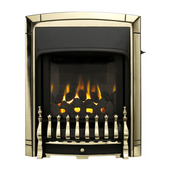
INSET LIVE FUEL EFFECT GAS FIRE
INCORPORATING THE
BAXI FIRES DIVISION
CONTROL
With
ALPHA, DECADENT,
DREAM, ELEGANT,
ETERNAL
or
OBSESSION
fascia
(GC No. 32-032-58)
THIS APPLIANCE IS FOR USE WITH NATURAL GAS (G20).
WHEN CONVERTED USING CONVERSION KIT NO. 0595221 THIS
APPLIANCE IS FOR USE WITH PROPANE GAS (G31).
THIS APPLIANCE IS SUITABLE ONLY FOR INSTALLATION IN THE UNITED
KINGDOM (GB) AND THE REPUBLIC OF IRELAND (IE).
We trust that this guide gives sufficient details to enable this appliance to be installed
and maintained satisfactorily. However, if further information is required, our
Baxi Fires Division Technical Helpline will be pleased to help.
Telephone 08706 061 065 (National call rates apply in the United Kingdom)
In the Republic of Ireland telephone 0044 8706 061 065.
INSTALLER: Please leave this guide with owner
© Baxi Heating U.K. Ltd.
Advertisement
Table of Contents

Subscribe to Our Youtube Channel
Related Manuals for Baxi Fires Division 750


Summary of Contents for Baxi Fires Division 750
- Page 1 We trust that this guide gives sufficient details to enable this appliance to be installed and maintained satisfactorily. However, if further information is required, our Baxi Fires Division Technical Helpline will be pleased to help. Telephone 08706 061 065 (National call rates apply in the United Kingdom) In the Republic of Ireland telephone 0044 8706 061 065.
- Page 2 BS EN ISO 9001 quality system accepted by the British Standards Institute. The Highest Standards Baxi Fires Division is a member of the Society of British Gas Industries which works to ensure high standards of safety, quality and performance. Careful Installation Baxi Fires Division is a CORGI registered company.
-
Page 3: Table Of Contents
INSTALLER GUIDE CONTENTS Section Heading Page 1. SAFETY 2. APPLIANCE DATA 3. GENERAL INSTALLATION REQUIREMENTS 4. PACK CONTENTS 5. FIREPLACE CHECK 6. IGNITION CHECK 7. GAS SUPPLY CONNECTION 8. PREPARING APPLIANCE FOR INSTALLATION 9. CONVECTION BOX INSTALLATION 9.1 Method 1- Front fixing to fireplace surround. 9.2 Method 2 - Cable retention. -
Page 4: Safety
INSTALLER GUIDE 1. SAFETY Installer Before continuing any further with the installation of this appliance please read the following guide to manual handling. The lifting weight of this appliance is as below: - Model Heat Engine (kg) Firefront (kg) Combined Weight (kg) Alpha 2.10 10.00... -
Page 5: Appliance Data
INSTALLER GUIDE 2. APPLIANCE DATA This product uses fuel effect pieces and a burner compartment rear wall containing Refractory Ceramic Fibres (RCF), which are man-made vitreous silicate fibres. Excessive exposure to these materials may cause irritation to eyes, skin and respiratory tract. Consequently, it is important to take care when handling these articles to ensure that the release of dust is kept to a minimum. -
Page 6: General Installation Requirements
INSTALLER GUIDE 3. GENERAL INSTALLATION REQUIREMENTS The installation must be in accordance with this guide. For the user’s protection, in the United Kingdom it is the law that all gas appliances are installed by competent persons in accordance with the current edition of the Gas Safety (Installation and Use) Regulations. - Page 7 INSTALLER GUIDE and having a minimum effective flue height of 3m (10ft). A masonry chimney having a correctly installed flue liner to BS EN 1856 part 1 or BS715 and with a minimum flue diameter of 125mm is also acceptable. Chair brick removal may not be required providing at least 50mm clearance is...
- Page 8 INSTALLER GUIDE 3.2.2 To a fireplace incorporating a metal flue box conforming to BS EN 1856 part 1 or BS715 with a minimum internal depth of 165mm. Incombustible mineral wool insulation of not less than 50mm thickness must be applied to the top surface of the firebox (See figure 2) and it must stand on a non-combustible hearth (See figure 1).
- Page 9 INSTALLER GUIDE The current versions of BS1289 and BS EN 1858 recommend that there should be an air space or insulation between the flue blocks and the plaster because heat transfer may cause cracking on directly plastered flues. However, generally this appliance is suitable for installations under all circumstances unless there is a history of cracking problems.
- Page 10 INSTALLER GUIDE 3.7 If the appliance is intended to be installed to a chimney, which was previously used for solid fuel, the flue must be swept clean prior to installation. All flues should be inspected for soundness and freedom from blockages. 3.8 If the fireplace opening is an underfloor draught type, it must be sealed to stop any draughts.
- Page 11 INSTALLER GUIDE 3.12 Note that soft wall coverings (e.g. embossed vinyl, etc.) are easily affected by heat. They may scorch or become discoloured when close to a heating appliance. Please bear this in mind when installing. 3.13 The appliance must not be installed in any room, which contains a bath, or shower or where steam is regularly present.
- Page 12 INSTALLER GUIDE 3.20 The minimum allowable distance from the outside of the fascia to a corner wall having combustible material or any other combustible surface which projects beyond the front of the appliance is shown in figure 4. For access purposes the recommended clearances to non combustible surfaces are shown in figure 4.
-
Page 13: Pack Contents
INSTALLER GUIDE 4. PACK CONTENTS The items required for this appliance are packed in sections. Section 1 - Fire unit contains: 1 Inlet “T” connector including pressure 1 Convection box and burner assembly test point 1 Loose parts pack including: - 1 Burner tray trim (Not supplied on 1 Grommet for rear of convection box ‘Eternal’) - Page 14 INSTALLER GUIDE Figure 6. Pack contents continued Page 14...
-
Page 15: Fireplace Check
INSTALLER GUIDE Obsession Figure 6. Pack contents continued 5. FIREPLACE CHECK 5.1 Fireplace check. 5.1.1 Fireplace size The fireplace must comply with the requirements described in section 3.2. This may entail removing the fireback and infill material behind the fireback. 5.1.2 Fireplace general condition The fireplace floor should be reasonably flat to ensure that the convector box can be installed without it rocking and so that a good seal can be made at the bottom front of... -
Page 16: Ignition Check
INSTALLER GUIDE The methods are detailed in section 9 of this manual. Before selecting the retention method, consult with the customer. Method 2 is provided for instances where drilling holes in the front surface of the fireplace surround is unacceptable to the customer or otherwise impractical. -
Page 17: Gas Supply Connection
INSTALLER GUIDE Figure 8. Slider control 7. GAS SUPPLY CONNECTION A nut and olive are provided for an 8mm pipe inlet connection to the inlet ‘T’ connector at the bottom front of the appliance. The inlet ‘T’ connector can be rotated to allow a connection from any direction. -
Page 18: Preparing Appliance For Installation
INSTALLER GUIDE 8. PREPARING APPLIANCE FOR INSTALLATION 8.1 Appliance preparation 1. Remove any transit tape and packing and inspect for any evidence of mishandling which might affect the performance. Each unit is flame tested before it leaves the factory and as a result there may be slight discolouration around the burner ports. -
Page 19: Convection Box Installation
INSTALLER GUIDE the restrictor causes the fire to fail the spillage test. In such cases the restrictor will have to be removed. After removal conduct the spillage check again. Fit the restrictor as shown in figure 11 using the two screws provided. Figure 11. -
Page 20: Method 2 - Cable Retention
INSTALLER GUIDE 9.2 Method 2 - Cable retention. 1. Make sure that the relevant areas at the fireplace back are sound enough to take the eyebolts. If these areas have deteriorated due to prolonged use they should be made sound with a suitable cement. 2. -
Page 21: Floor Sealing
INSTALLER GUIDE 8. Fit a cable retainer over the bottom end of each cable. 9. Pull each cable taut. Push the cable retainers hard up against the back panel. Tighten the screws in the retainers so that they clamp the cables in position. -
Page 22: Burner Installation
INSTALLER GUIDE 10. BURNER INSTALLATION 10.1 Burner and supply pipe installation. 1. Refit the burner unit to the convection box with two screws. 2. Connect the supply line to the appliance. 3. Pressure check the installation pipework for gas soundness. In the United Kingdom check in accordance with the current edition of BS6891. -
Page 23: Fitting The Fascia
INSTALLER GUIDE 2. After checking, turn off the appliance. Remove the pressure gauge and replace the test point sealing screw. 3. Relight the appliance. Turn to the maximum output position and test around the sealing screw for gas soundness with a suitable leak detection fluid. 10.4 Fitting the burner tray trim. -
Page 24: Fitting The Ceramic Fuel Effect
INSTALLER GUIDE a screwdriver (Not finger tight only) (See figure 22). Dream, Eternal and Obsession models only. 1. Supplied with the fire is a self adhesive control position label. Peel the backing from the label and place as in figure 23. Figure 21. -
Page 25: Firefront Casting Installation
INSTALLER GUIDE 13. FIREFRONT CASTING INSTALLATION 13.1 Fitting the Alpha, Eternal, Elegant and Obsession firefront casting. 1. Fit the fire front casting to the fascia. Locate the two screw heads at the rear top corners of the casting through the keyhole slots at the inner sides of the fascia. -
Page 26: Full Operating Checks
INSTALLER GUIDE 14. FULL OPERATING CHECKS 14.1 Recheck the control settings. The control position markings on the fascia are shown in figure 27. Please note: When first turned on from cold, the flames will appear predominantly blue. When operating the fire for the first time, some vapours may be given off which could set off smoke alarms in the vicinity. -
Page 27: Spillage And Flame Supervision Checks
INSTALLER GUIDE 15. SPILLAGE AND FLAME SUPERVISION CHECKS 15.1 Check for spillage. A spillage check must be made before leaving the installed appliance with the customer. Make this with all the ceramic fuel effect pieces, fascia and firefront in position. 1. -
Page 28: Final Review
INSTALLER GUIDE for one minute. 2. Set the control to the ‘Low’ burning position. Isolate the gas supply at the inlet ‘T’ connector. The pilot and main burner will go out. Note the time when the pilot goes out. Listen for a snap sound at the gas tap. Note the time when the sound is heard. This sound is caused by an electromagnetic valve shutting off the gas supply through the tap. -
Page 29: Servicing & Parts Replacement
INSTALLER GUIDE 9. Advise the customer that the castings, fascia, firebox and ceramic pieces can be cleaned as described in the owner guide and that the loose ceramic fuel effect pieces must be replace as described in those instructions. Stress that no extra ceramic fuel effect pieces must be added over and above those supplied with the appliance and that any replacements must only be the authorised spares. -
Page 30: Checking The Aeration Setting Of The Burner
INSTALLER GUIDE 17.1 Checking the aeration setting of the burner. It is important to 1. The aeration shutter is factory set and will require adjustment. ensure that the aeration setting is correct (See figure 29). 2. To adjust the aeration setting, loosen the two aeration shutter screws, slide the aeration shutter to the position shown in figure 29 and tighten the fixing screws. -
Page 31: To Remove The Fascia
INSTALLER GUIDE sure that they are secured firmly to give a good electrical contact. 17.4 To remove the fascia. 1. Remove the firefront casting and the front cover casting. 2. Detach the control-linking bar from the control pivot bracket by removing the knurled screw, which joins the control linking bar to the control pivot unit (See figure 33). -
Page 32: To Remove The Burner Unit
INSTALLER GUIDE 17.6 To remove the burner unit. 1. Remove the fascia (See section 17.4). 2. Remove the loose ceramic fuel effect 3. Support the inlet ‘T’ connector to avoid straining the pipework and disconnect the appliance from the inlet ‘T’ connector. -
Page 33: To Remove The Pilot Unit
INSTALLER GUIDE 17.9 To remove the pilot unit. 1. Remove the burner unit (See section 17.6). 2. Detach the pilot pipe from the pilot unit. 3. Detach the thermocouple from the interrupter block by unscrewing the thermocouple nut. 4. Detach the electrode lead from the underside of the electrode tab. -
Page 34: To Remove The Gas Flow Rate Controller
INSTALLER GUIDE tap and fit to the replacement tap. Refit in the reverse order. When refitting, make sure that the tap spindle is in the correct relationship relative to the control pivot bracket. Rotate the pivot bracket fully clockwise. The tap spindle should “bottom out” (i.e. the tap should be fully open) after the pivot bracket has actuated the ignition microswitch but before it has pushed the microswitch leaf against the microswitch body. -
Page 35: To Remove The Main Burner Injector
INSTALLER GUIDE 17.13 To remove the main burner injector. (See figure 44). 1. Remove the burner (See section 17.12). 2. Remove the burner clamping screw (See figure 3. Unscrew the injector from the burner 4. Refit in the reverse order. 17.14 To remove the appliance from the fireplace.
Need help?
Do you have a question about the 750 and is the answer not in the manual?
Questions and answers