Table of Contents
Advertisement
Quick Links
F-rat-nx75
Operating Instructions
Make sure to read this manual carefully before using, and start using only after you have
understood all the product' s functions, safety information and precautions.
After reading the instructions, store the booklet in a designated location for readily accessing at
any time.
Specifications subject to change without notice
2 Great Valley Blvd., Wilkes-Barre, PA 18706
Office Ph: 570-820-8811
Fax: 570-820-8838
www.itohdenki.com
Advertisement
Table of Contents

Subscribe to Our Youtube Channel
Related Manuals for ITOH DENKI F-RAT-NX75


Summary of Contents for ITOH DENKI F-RAT-NX75
- Page 1 F-rat-nx75 Operating Instructions Make sure to read this manual carefully before using, and start using only after you have understood all the product’ s functions, safety information and precautions. After reading the instructions, store the booklet in a designated location for readily accessing at any time.
-
Page 2: Table Of Contents
table of contents Subject page Introduction Procedures Safety Precautions 6-11 Advance Preparation 12-14 Product Check Structures 16-17 Installation/Wiring -Before Installation 18-32 -Installation -Wiring Control/Operation -Basic Operation -Switching the Transfer Direction 33-39 -Changing the Speed -What to do Before Operation -Timing Chart Example Maintenance/Inspection -Driver card LED Display and Errors 40-50... -
Page 3: Introduction
introduction Features: This product is a module to divert at a right angle without changing its level, and there is no impact on the trays. All-electric control. No pneumatics, which do not require compressor. operation description (when diverting): Load Switch to the diverting direction Discharge Switch to the straight direction 2 Great Valley Blvd., Wilkes-Barre, PA 18706... - Page 4 In this manual, F-RAT-NX75 is described as F-RAT, and F-RAT-NX75 and F-RAT are described separately, when needed. Depending on the signal type (NPN/PNP) specified by customers, different models of control driver cards are supplied as being the standard for this product.
-
Page 5: Procedures
procedures Start using only after you have understood all the product´s functions, Read this Manual safety information, and precautions. Prepare the 24V DC power supply, such as DC power supply units. Prepare Advance Preparation control devices, such as PLCs. Open the package, and check the model, specifications, and voltage, etc. Product Check Check accessories. -
Page 6: Safety Precautions
Safety Precautions Danger Level: To prevent hazards to users and/or others, and/or damage to property in advance, the important precautions to be followed securely are described below. The degree of hazard and/or damage that may result if a user disregards the description and operates the product improperly is categorized as the following symbols and explained below. - Page 7 Safety Precautions General Precautions (Continued): CAUTION Do not forcibly bend and/or pull cables. Also, do not put heavy materials on cables, or do not get them stuck between cables. Failure to follow this could result in fire and/or electric shock due to cable damage. Never remodel the product and/or driver cards.
- Page 8 Safety Precautions General Precautions (Continued): CAUTION Do not unplug power and/or signal cables during operation. Also, do not run/stop this product by the power supply. (Use the signal.) Failure to follow this could result in malfunction. Do not forcibly rotate the MDR at times other than maintenance and inspection. Failure to follow this could result in damage to driver cards, and/or their lifetime to be significantly shortened.
- Page 9 Safety Precautions INSTALLATION Precautions (continued): CAUTION Take appropriate measures to prevent trays from popping out of the equipment. For example, mount guide rails on the conveyor frames. Failure to follow this could result in workers getting injured by trays popping out of the equipment. If necessary, warning/caution labels become hidden after installing fences, affix again on places where they can be seen.
- Page 10 Safety Precautions OPERATING Precautions: CAUTION Do not forcibly move trays when they are placed on the carrier wheels. Failure to follow this could result in damage and/or malfunction. Make sure to perform the start-up inspection before starting operation. Wear protective equipment, such as gloves. At the start-up inspection, shut off the power, and perform inspection.
- Page 11 Check that all parts are installed. Failure to follow this could result in malfunction and/or unexpected accidents. Make sure to prepare repair/replacement parts designated by ITOH DENKI. Using parts other than those designated by ITOH DENKI could result in malfunction.
-
Page 12: Advance Preparation
Advance Preparation wiring reference: IB-E Series Important: As for the sensor input, and input/output signals of driver cards, adopt the number of inputs/outputs based on operation. CB Series 2 Great Valley Blvd., Wilkes-Barre, PA 18706 Office Ph: 570-820-8811 Fax: 570-820-8838 www.itohdenki.com... - Page 13 Advance Preparation items to be prepared by customers: Before introducing this product, prepare the following devices separately. 1. Emergency Stop Equipment This product does not include the emergency stop equipment. Customers must make sure to install it. Install the emergency stop equipment on the side of the DC power supply unit to which the power is supplied.
- Page 14 Advance Preparation items to be prepared by customers (Continued): 2. Control Devices: devices to control this product, such as PLCs 3. Sensors: Zone sensors to check the tray, and area sensors to check loading and discharging, etc. Zone Sensor: A sensor to detect the existence of trays within the zone Area sensor: A sensor to detect load and discharge of trays...
-
Page 15: Product Check
Product Check checking the model: Unpack the product, and check that the product model is what you ordered. checking appearance: Check that the main unit is free from any abnormalities, such as traces of scratches, dents, dirt, and/or corrosion (rust). Check that there is no omission and/or looseness of screws. - Page 16 Product Check checking accessories: Check that all the following items are included. Driver Cards Depending on the F-RAT input and output signal type, driver cards with the NPN (N) or PNP(P) signal input are available. For installing the F-RAT main unit 2 Great Valley Blvd., Wilkes-Barre, PA 18706 Office Ph: 570-820-8811 Fax: 570-820-8838...
-
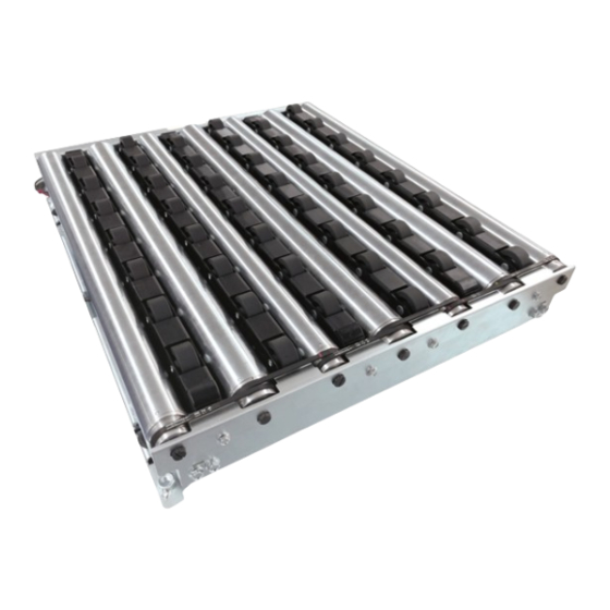
Page 17: Structures
structures Structures: *The image is for size 7550 Product Designation: Nominal Speed: The speed on the MDR roller surface (m/min), and the nominal speed with a nice round value for convenience. Values differ slightly from the actual speed. 2 Great Valley Blvd., Wilkes-Barre, PA 18706 Office Ph: 570-820-8811 Fax: 570-820-8838 www.itohdenki.com... -
Page 18: Installation/Wiring
installation/wiring 7-1. Before installation Prepare stands, and perform frame processing in advance by reference to the mounting holes in dimensions. Determine the mounting location for zone sensors to check the existence of trays, and area sensors to check loading and discharging. Then, prepare for them to be mounted. Dimensions of F-rat main unit: Size 6040 L595mm x W395mm... - Page 19 installation/wiring Size 6060 L595mm x W595mm Size 6070 L595mm x W695mm 2 Great Valley Blvd., Wilkes-Barre, PA 18706 Office Ph: 570-820-8811 Fax: 570-820-8838 www.itohdenki.com...
- Page 20 installation/wiring Size 6080 L595mm x W795mm Size 7540 L745mm x W395mm 2 Great Valley Blvd., Wilkes-Barre, PA 18706 Office Ph: 570-820-8811 Fax: 570-820-8838 www.itohdenki.com...
- Page 21 installation/wiring Size 7550 L745mm x W495mm Size 7560 L745mm x W595mm 2 Great Valley Blvd., Wilkes-Barre, PA 18706 Office Ph: 570-820-8811 Fax: 570-820-8838 www.itohdenki.com...
- Page 22 installation/wiring Size 7570 L745mm x W695mm Size 7580 L745mm x W795mm 2 Great Valley Blvd., Wilkes-Barre, PA 18706 Office Ph: 570-820-8811 Fax: 570-820-8838 www.itohdenki.com...
- Page 23 installation/wiring Size 9040 L895mm x W395mm Size 9050 L895mm x W495mm 2 Great Valley Blvd., Wilkes-Barre, PA 18706 Office Ph: 570-820-8811 Fax: 570-820-8838 www.itohdenki.com...
- Page 24 installation/wiring Size 9060 L895mm x W595mm Size 9070 L895mm x W695mm 2 Great Valley Blvd., Wilkes-Barre, PA 18706 Office Ph: 570-820-8811 Fax: 570-820-8838 www.itohdenki.com...
- Page 25 installation/wiring Size 9080 L895mm x W795mm 2 Great Valley Blvd., Wilkes-Barre, PA 18706 Office Ph: 570-820-8811 Fax: 570-820-8838 www.itohdenki.com...
- Page 26 installation/wiring Mounting Preparation for driver cards: Perform mounting processing on the frames and control panel by reference to the mounting holes for controllers. For cable opening and projection from the F-RAT main unit, refer to F-RAT dimensions (P.18-25). Mount driver cards on a flat surface where heat can be released easily. Prevent chips generated during processing from entering controllers.
- Page 27 installation/wiring Preparing mdr extension cables: If the mounting location of the F-RAT main unit is far from that of driver cards, prepare the MDR extension cables separately. For CBK-109 or IB-E04 1 2P extension cable): M-F-EXT-12PIN-(600/1200) ( For CB-016B or IB-E03 1 0P extension cable): M-F-EXT-10PIN-(600/1200) (...
-
Page 28: Installation
installation/wiring 7-2: Installation Necessary Tools Installing the f-rat main unit: 1. Carry product to the installing location When lifting, hold the bottom of this product. Do not hold the moving parts, such as rollers, belt transfer parts, or lifting sections. 2. - Page 29 installation/wiring Installing the f-rat main unit (Continued): 4. Adjust the conveyor frame legs on which the F-RAT main unit has been mounted, and align levels of the F-RAT main unit and the adjacent conveyor. Mounting Driver cards: Use the included screws and nuts to mount driver cards on the conveyor frames or control panel.
- Page 30 installation/wiring Wiring for CBK-109: M1:For carrier wheel transfer Power connector (CN1) Connect the 24V DC and 0V DC cables to CN1 (2 pin). Do not connect multiple power cables to one pole. Failure to follow this could result in electric shock, short circuit, and/or damage due to the capacity of connectors being exceeded.
- Page 31 installation/wiring wiring for cb-016: M2:For roller transfer Power connector (CN1) Connect the 24V DC and 0V DC cables to CN1 (2 pin). Do not connect multiple power cables to one pole. Failure to follow this could result in electric shock, short circuit, and/or damage due to the capacity of connectors being exceeded.
- Page 32 installation/wiring Settings for M1: CBK-109 / M2 and M3: CB-016: Turn the driver card volume to the following (factory setting). The carrier wheel speed for this product of the nominal speed of 17 m/min type is 61.5 m/min (factory setting). To set it to the approximate roller speed, change the speed.
-
Page 33: Control/Operation
control/operation 8-1: Basic operation device configuration image: Zone sensor: a sensor to detect the existence of trays within the zone Area sensor: a sensor to detect load and discharge of trays Loading and discharging directions will be changed depending on the SW1#3 setting and signal input to CN2. 2 Great Valley Blvd., Wilkes-Barre, PA 18706 Office Ph: 570-820-8811 Fax: 570-820-8838... - Page 34 control/operation 8-2: Switching the transfer direction M1: CBK-109 / M2: CB-016 The transfer direction can be set by DIP-SW on the driver card, and signal input When changing the direction, check the F-RAT main unit installation direction. The transfer direction cannot be changed by SW1#3 during transfer (while MDR is running).
- Page 35 control/operation 8-3: Changing the transfer speed M1: CBK-109 / M2: CB-016 There are two types of settings to change speed: the internal speed setting to change the speed by switches on the driver card, and the external speed setting to change the speed by inputting the analog voltage to CN2#3.
- Page 36 control/operation Speed Charts: M1: Carrier Wheel Speed Speed accuracy: ±3% SW1#5 ON SW1#5 OFF Setting 61.5 56.4 53.9 51.3 48.7 46.2 41.1 38.4 35.9 33.4 30.8 28.2 25.6 23.1 20.5 18.0 15.5 12.8 10.3 Rated 59.8 56.4 53.9 51.3 48.7 46.2 41.1 38.4 35.9 33.4 30.8 28.2 25.6 23.1 20.5 18.0 15.5 12.8 10.3 External voltage Input (V)
- Page 37 control/operation 8-4: What to do before operation Items to check before turning on the power: Turn off the power of all connected devices, and perform the following inspection, taking necessary measures. Turn off the power, wait a sufficient amount of time, and discharge electricity inside the DC power supply equipment.
- Page 38 control/operation 8-5: Timing chart example 2 Great Valley Blvd., Wilkes-Barre, PA 18706 Office Ph: 570-820-8811 Fax: 570-820-8838 www.itohdenki.com...
- Page 39 control/operation trial Run: Check the following before the trial run. When the roller transfer MDR and/or idlers have been replaced, check that the drive belts have been mounted in the correct groove positions. Check all parts are installed. Performing the trial run: When the start-up inspection has finished, perform the trial run with careful attention to the following points, and check that operation is correctly performed.
-
Page 40: Maintenance/Inspection
maintenance/inspection 9-1: Driver Card led display and errors If errors occur with this product, identify the cause of errors, and perform recovery work. Checking the driver card status: Identify the cause of errors by checking LEDs and error signal output on driver cards, and restore the product. CBK-109 (for carrier wheel transfer) LED display explanation: Errors can be checked by PWR (Green), ERR (Red), and signals from CN2#4... - Page 41 maintenance/inspection CB-016 (for roller transfer) LED display explanation: Errors can be checked by PWR (Green), ERR (Red), and signals from CN2#4 When error signals have been released by CN2#1 (RUN / STOP), the F-RAT instantly starts up when RUN is input. When the power supply voltage becomes insufficient, operation may be disabled, or an unexpected operation may occur.
- Page 42 40 type Size 70 type Size 50 type Size 80 type Size 60 type Example: Carrier wheel cassette Type B for F-RAT-NX75-F60- 75 50-CN: NX75-CC- 75 B 2 Great Valley Blvd., Wilkes-Barre, PA 18706 Office Ph: 570-820-8811 Fax: 570-820-8838 www.itohdenki.com...
- Page 43 The part number of which only belts, size □□60*1 type, are used to link Φ38 idlers, is 2PJ-246. 1 Indicates size (W direction) for the model of this product * Example: F-RAT-NX75-F60-7560-CN Roller transfer MDR PM486FE-(17/60)*2 Size 60 *1 ◻◻...
-
Page 44: Before Replacement Work
maintenance/inspection 9-3: Replacement of roller transfer MDR/idlers /roller drive belts If any abnormalities are found in one of the roller transfer MDR, idlers, and/or roller drive belts, replace them according to the following methods. before REPLACEMENT: Before replacement, prepare necessary tools. Turn off the power of all connecting devices. - Page 45 maintenance/inspection 2. Remove idlers (continued) 2-2: Slide the spring-loaded shaft from the fixed hole (①), and remove the idler from the frame (②). 2-3: Remove the roller drive belt, and remove the idler The roller drive belt can be removed easily by pulling it while turning the idler.
- Page 46 maintenance/inspection 3. Remove the roller transfer MDR (continued) 3-2: Lift up the tip of the roller transfer MDR (①), and remove the roller drive belt. (②) Remove the roller transfer MDR (③), and pull the power cable off the fixed hole on the frame (④) 4.
- Page 47 maintenance/inspection 4. Mounting roller transfer MDR/idlers/roller drive belts (continued) 4-2: Mount the roller drive belt on the V-ribbed pulley of the roller transfer MDR (①), align the tip of the attaching shaft with the notch shape, and fit it into the frame (②) For the mounting groove position for drive belts, refer to the figure below.
- Page 48 maintenance/inspection 5. Mount the idler (continued) 5-2: Align the tip of the attaching shaft on the side of the belt on the V-ribbed pulley, where the roller drive belt has been mounted, with the notch shape on the frame, and fit it into the frame Press the D-shaped cut surface of the axis onto the plate, and fit it into the frame.
- Page 49 maintenance/inspection 9-4: Replacing the carrier wheel cassette If any abnormalities are found in the carrier wheels, replace the whole carrier wheel cassette. Before replacement: 1. Prepare necessary tools 2. Turn off the power of all connecting devices Shut off the power switch, leave for three minutes or more, and discharge electricity inside the DC power supply equipment.
- Page 50 maintenance/inspection 3. Mounting the carrier wheel cassette on the F-RAT main unit 3-1: Check the model of the removed carrier wheel cassette and replacement carrier wheel cassette. Indication example: NX-75CC 75A This part of the carrier wheel cassette is indicated on the product 3-2: Mount the replacement carrier wheel cassette with hex.
-
Page 51: Troubleshooting
troubleshooting When troubleshooting, check the items shown below before contacting us or requesting a repair. Problem Items to be Checked Countermeasures References Is PWR LED (green) for each controller turned on? Installation/Wiring Or, has 24V DC been supplied in the Supply 24V DC. - Page 52 troubleshooting When troubleshooting, check the items shown below before contacting us or requesting a repair. Problem Check the Following Perform the Following Refer to Is the load conveyor level the same Align levels of the load conveyor Installation/Wiring as the level of the F-RAT? and the F-RAT.
- Page 53 troubleshooting When troubleshooting, check the items shown below before contacting us or requesting a repair. Problem Check the Following Perform the Following Refer to To change the carrier wheel speed, To change the carrier wheel have you operated the switch on speed, operate the switch on the the driver card for M1: carrier driver card for M1: carrier wheels...
-
Page 54: Appendix 1: Product Specifications
Appendix 1: Product Specifications f-rat main unit specifications: Values of the maximum load weight are reference only since they may change depending on tray conditions. * Depending on the bottom shape of trays, they may not be transferred normally, even if they are within the above size range. - Page 55 Appendix 1: Product Specifications Driver Card specifications: 2 Great Valley Blvd., Wilkes-Barre, PA 18706 Office Ph: 570-820-8811 Fax: 570-820-8838 www.itohdenki.com...
- Page 56 Appendix 1: Product Specifications Transfer throughput: Values on the graph are only references based on our measurement and are not guaranteed. * Slug release data is based on the total control by using idLinx for controlling the conveyors * before and after F-RAT. The stopping distance of trays and throughput depends on the size, material, bottom status of *...
- Page 57 Do not store carrier wheel cassettes in places subject to high temperature, high humidity, and/or direct sunlight. Failure to follow this could result in its lifetime to be significantly shortened. 1 Indicates size (L direction) for the model of this product. Example) F-RAT-NX75-F60-7550 *...
-
Page 58: Appendix 3: Residual Risk List
Appendix 3: Residual Risk/map residual risk list: WARNING: Indicates that there is a possibility that severe injury or even death may result if protective measures have not been taken CAUTION: Indicates that there is a possibility that minor injury may result if protective measures have not been taken residual risk map: 2 Great Valley Blvd., Wilkes-Barre, PA 18706...
Need help?
Do you have a question about the F-RAT-NX75 and is the answer not in the manual?
Questions and answers