Table of Contents
Advertisement
Quick Links
Technical Support and E-Warranty Certificate www.vevor.com/support
BENCH DRILL PRESS
INSTRUCTION MANUAL
DP1006L
MODEL:
We continue to be committed to provide you tools with competitive price.
"Save Half", "Half Price" or any other similar expressions used by us only represents an
estimate of savings you might benefit from buying certain tools with us compared to the major
top brands and doses not necessarily mean to cover all categories of tools offered by us. You
are kindly reminded to verify carefully when you are placing an order with us if you are
actually saving half in comparison with the top major brands.
Advertisement
Table of Contents

Subscribe to Our Youtube Channel
Related Manuals for VEVOR DP1006L


Summary of Contents for VEVOR DP1006L
- Page 1 Technical Support and E-Warranty Certificate www.vevor.com/support BENCH DRILL PRESS INSTRUCTION MANUAL DP1006L MODEL: We continue to be committed to provide you tools with competitive price. "Save Half", "Half Price" or any other similar expressions used by us only represents an estimate of savings you might benefit from buying certain tools with us compared to the major top brands and doses not necessarily mean to cover all categories of tools offered by us.
- Page 2 CustomerService@vevor.com This is the original instruction, please read all manual instructions carefully before operating. VEVOR reserves a clear interpretation of our user manual. The appearance of the product shall be subject to the product you received. Please forgive us that we won't inform you again if there are any technology or software updates on our product.
-
Page 3: Table Of Contents
TABLE OF CONTENTS SECTION PAGE PRODUCT SPECIFICATIONS................2 SAFETY GUIDELINES -DEFINITIONS..............3 PROPOSITION 65 WARNING................5 POWER TOOL SAFETY..................5 ADDITIONAL SAFETY RULES FOR DRILL PRESSES..........9 ELECTRICAL REQUIREMENTS AND SAFETY............11 TOOLS NEEDED FOR ASSEMBLY..............15 CARTON CONTENTS..................15 KNOW YOUR DRILL PRESS................18 GLOSSARY OF TERMS..................19 ASSEMBLY AND ADJUSTMENTS ...............21 OPERATION ......................32 MAINTENANCE....................40... -
Page 4: Safety Guidelines-Definitions
LAMP Spindle Travel 2 in. (50 mm) Speeds (RPM) 610~2800 RPM Chuck Size 1/2 in. (13 mm) Column Size 1-718 in. (48 mm) To avoid electrical hazards,fire hazards or damage to the tool, use proper circuit protection. Use a separate electrical circuit for your tools. The drill press is wired at the factory for 120 Volt operation. - Page 5 WEAR RESPIRATORY AND HEARING PROTECTION: Always wear respiratory and hearing protection. READ AND UNDERSTAND INSTRUCTION MANUAL: To reduce the risk of injury, user and all bystanders must read and understand instruction manual before using this product. KEEP HANDS AWAY FROM THE MOVING PART AND CUTTING SURFACE: Failure to keep your hands away from the moving part and to cut surface will result in serious personal injury.
-
Page 6: Proposition 65 Warning
PROPOSITION 65 WARNING Drilling,sawing,sanding or machining wood products can expose you to wood dust, a substance known to the State of California to cause cancer. Avoid inhaling wood dust or use a dust mask or other safeguards for personal protection. For more information go to www.P65Warnings.ca.gov/wood Some examples of these chemicals are: ●... - Page 7 ● To avoid mistakes that could cause serious injury,do not plug the tool in until you have read and understood the following. ● Read all instructions before operating product.Failure to follow all instructions listed below may result in electric shock,fire and/or serious injury.
- Page 8 and nameplate ampere rating. If in doubt, use the next heavier gauge.The smaller the gauge number, the heavier the cord. 11. WEAR PROPER APPAREL. Do not wear loose clothing, gloves, neckties, rings, bracelets or other jewelry which may get caught in moving parts.Nonslip footwear is recommended.Wear protective hair covering to contain long hair.
- Page 9 parts,mounting and any other conditions that may affect its operation. A guard or other part that is damaged should be properly repaired or replaced. 20.NEVER LEAVE THE TOOL RUNNING UNATTENDED. TURN THE POWER “OFF”. Do not walk away from a running tool until the blade comes to a complete stop and the tool is unplugged from the power source.
-
Page 10: Additional Safety Rules For Drill Presses
ADDITIONAL SAFETY RULES FOR DRILL PRESS Following good safety practices when using drill presses is a must.Make a habit of including safety in all your activities. READALLINSTRUCTIONSBEFORE OPERATING PRODUCT. FAILURETO FOLLOW ALL INSTRUCTIONS LISTED BELOW MAY RESULT IN ELECTRIC SHOCK, FIRE AND OR SERIOUS INJURY. Do not operate this tool until it is assembled and installed according to the instructions. - Page 11 10. SECURE THE WORK. Use clamps or a vise to hold the work. It's safer than using your hand and it frees both hands to operate tool. 11. WHEN using a drill press vise,always fasten to the table. 12. MAKE SURE all clamps and locks are firmly tightened before drilling. 13.
-
Page 12: Electrical Requirements And Safety
24. TO AVOID INJURY from accidental starting, always turn the switch "OFF"and unplug the drill press before installing or removing any accessory or attachment or making any adjustments. 25. Be sure the chuck is tightly secured to the spindle. 26. USE ONLY THE SELF-EJECTING TYPE CHUCK KEY as provided with the drill press. - Page 13 This tool must be grounded while in use to protect the operator from electrical shock. IN THE EVENT OF A MALFUNCTION OR BREAKDOWN, grounding provides a path of least resistance for electric currents and reduces the risk of electric shock. This tool is equipped with an electrical cord that has an equipment-grounding conductor and a grounding plug.The plug must be plugged into a matching receptacle that is properly installed and grounded in accordance with all local codes and ordinances.
- Page 14 GUIDELINES FOR EXTENSION CORDS USE THE PROPER EXTENSION CORD. Make sure your extension cord is in good condition. Use an extension cord heavy enough to carry the current your product will draw.An undersized cord will cause a drop in line voltage resulting in loss of power, overheating and burning out of the motor.
- Page 15 This tool is for indoor use only. Do not expose to rain or use in damp locations. This tool is intended for use on a circuit that has a receptacle like the one illustrated in Fig.1.Fig.1 shows a three-pronged electrical plug and receptacle that has a grounding conductor.
-
Page 16: Tools Needed For Assembly
TOOLS NEEDED FOR ASSEMBLY CARTON CONTENTS UNPACKING AND CHECKING CONTENTS Carefully unpack the drill press and all its parts,and compare against the list below and the illustration on the next page. Place the drill press on a secure surface and examine it carefully. - 15 -... - Page 17 To avoid injury from unexpected starting or electrical shock, do not plug the power cord into a source of power during unpacking and assembly. The cord must remain unplugged whenever you are adjusting/assembling the drill press. The drill press is heavy and should be lifted with care. If needed, get ...
- Page 18 - 17 -...
-
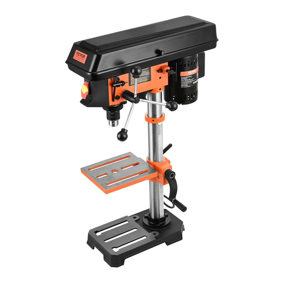
Page 19: Know Your Drill Press
KNOW YOUR DRILL PRESS - 18 -... -
Page 20: Glossary Of Terms
GLOSSARY OF TERMS BASE-Supports drill press.For additional stability, holes are provided in the base to bolt drill press to the floor.(See "ADDITIONAL SAFETY RULES FOR DRILL PRESSES".) BACKUP MATERIAL-Apiece of scrap wood placed between the workpiece and table.The backup board prevents wood in the workpiece from splintering when the drill passes through the backside of the workpiece.It also prevents drilling into the table top. - Page 21 ON/OFF SWITCH-Has locking feature. This feature is intended to help prevent unauthorized and possible hazardous use by children and others. Insert the key into the switch to tum the drill press on. DRILLING SPEED-Changed by placing the belt in any of the steps (grooves) in the pulleys.
-
Page 22: Assembly And Adjustments
ASSEMBLY AND ADJUSTMENTS Estimated Assembly Time: 25-35 Minutes. For your safety, never connect plug to power source receptacle until all assembly and adjustment steps are all complete, and you have read and understood the safety instructions. The drill press is a heavy power tool and should be lifted with the help ... - Page 23 INSTALLING THE TABLE(FIG.B~F) 1. Bag“G”-Install the table lock handle(1) into the hole at the rear of the table bracket (4). NOTE: Install the handle from left to right, so it enters the non-threaded side of the table bracket first. 2. Bag "G"- Insert the worm gear (2) into the table crank handle hole (3) from inside of the table bracket (4).
- Page 24 6. Install the rack ring (6) onto the column so the top lip of the rack sits into the rack ring (6).(Fig.E) NOTE: To avoid column or collar damage, DO NOT OVERTIGHTEN the set screw(7). The bottom of the collar MUST NOT be pushed all the way down onto the top of the rack.
- Page 25 7. Install the table crank handle (8) onto the worm gear shaft (9) on the side of the table bracket.(Fig.F) 8. Line up the flat side of the shaft with the set screw (10) in the crank handle and tighten the screw with the 3 mm hex wrench provided.Do not overtighten.
- Page 26 INSTALLING FEED HANDLES (FIG.H) 1. Bag“D”-Locate the three feed (1) in the loose parts bag. Handles 2. Thread each feed handle (1) into the (2) on the hub assembly (3) threaded holes and tighten. INSTALLING THE CHUCK(FIG.I,J) Before any assembly of the chuck and arbor to the drill press head, clean all mating surfaces with a non-petroleum-based product, such as alcohol or lacquer thinner.
- Page 27 6. Using a rubber mallet or a hammer and a block of wood, tap the chuck onto the spindle firmly.(Fig. J) REMOVING THE CHUCK(FIG.J) 1.Turn the feed handles to lower the chuck to the lowest position. 2. Place a ball joint separator (not shown) above the chuck and tap it lightly with a hammer or rubber mallet to cause the chuck to drop from the spindle.
- Page 28 CHUCK KEY STORAGE(FIG.K) Storage holder (1) for the chuck key (2) is located on the right side of the drill press. MOUNTING DRILL PRESS TO WORK SURFACE(FIG.L) The drill press must be securely fastened by the two base holes to a stand with heavy-duty fasteners.
- Page 29 ADJUSTMENTS INSTRUCTIONS NOTE: All the adjustments for the operation of the drill press have been completed at the factory. Due to normal wear and use, some occasional readjustments may be necessary. To avoid injury from an accidental start, ALWAYS make sure the switch is in the "OFF"position, the switch key is removed, and the plug is not connected to the power source outlet before making adjustments.
- Page 30 SPINDLE/QUILL(FIG.N) Rotate the feed handles counterclockwise to lower spindle to its lowest position. Hold the chuck and move it front to back. If there is excessive play, proceed with the following adjustments: 1. Loosen the lock nut (1)located on the right side of the drill press by using a 13 mm wrench.
- Page 31 QUILL RETURN SPRING (FIG.O) The quill return spring may need adjustment if the quill return speed is too fast or too slow. This spring is located on the left side of the drill head. 1. Lower the table for additional clearance. 2.
- Page 32 BELT TENSION (FIG.P) To avoid injury from an accidental start, ALWAYS make sure the switch is in the "OFF" position, the switch key is removed, and the plug is not connected to the power source outlet before making belt adjustments. 1.
-
Page 33: Operation
series and AA size or equivalent). When replacing the batteries, the battery guide should be thoroughly cleaned. Use a soft paintbrush or similar device, to remove all sawdust and debris. Do not mix old and new batteries.Do not mix alkaline, standard (carbon - zinc), or rechargeable (nickel-cadmium) batteries. - Page 34 DRILLING SPEED TABLE (RPM) Material Drill Bit Alum. / Diameter (Inches) Wood Zinc. / Iron / Steel Brass 1/16 2800 2800 2080 3/16 1500 2800 2080 5/16 1500 2080 ON/OFF SWITCH (FIG.S) The ON/OFF switch has a removable, safety key. With the safety key removed from the switch, unauthorized and hazardous use by children and others is minimized.
- Page 35 switch (2). Move the switch upward to the "ON"position. 2. To turn the drill press "OFF", move the switch downward. 3. To lock the switch in the OFF position, grasp the sides of the safety key, and pull it out. 4.
- Page 36 INSTALLING DRILL BIT IN CHUCK (FIG.U) 1. With the switch "OFF"and the safety key removed, open the chuck jaws (1) using the chuck key (2). Turn the chuck key counterclockwise to open the chuck jaws(1). 2. Insert the drill bit (3) into the chuck far enough to obtain maximum gripping by the jaws, but not far enough to touch the spiral grooves (flutes) of the drill bit when the jaws are tightened.
- Page 37 4. Spin the lower nut (3) down to contact the depth stop lug (4). 5. Spin the upper nut (5) down and tighten against the lower nut (3). 6. The drill bit(2) will now stop after traveling the distance marked on the workpiece.
- Page 38 DRILL A HOLE Using a centre punch or a sharp nail, make an indentation in the workpiece where you want to drill. Turn the power switch on and pull down on the feed handles with only enough effort to allow the drill to cut. FEEDING TOO RAPIDLY might cause the belt or drill to slip, tear the workpiece loose, or break the drill bit.
- Page 39 3. For a small piece that cannot be clamped to the table, use a drill press vise (optional accessory). When using a drill press vise, it MUST be clamped or bolted to the table to avoid injury from a spinning workpiece, or damaged vise or bit parts. TILTING THE TABLE(FIG.Z) 1.
- Page 40 To prevent injury, be sure to hold the table and table arm assembly, so it will not swivel or tilt. To avoid injury from spinning work or tool breakage, always clamp workpiece and backup material securely to the table before operating the drill press.
-
Page 41: Maintenance
MAINTENANCE For your own safety, turn the switch off and remove the plug from the power source outlet before maintaining or lubricating your drill press. GENERAL MAINTENANCE Frequently blow out dust and grit that accumulates in the motor housing using compressed air. ALWAYS use safety glasses. -
Page 42: Accessories And Attachments
replace it immediately. LUBRICATION Ball bearings in the drill press are packed with grease at the factory and require no further lubrication. Use only mild soap and a damp cloth to clean the tool. Never let any liquid get inside the tool; never immerse any part of the tool in a liquid. IMPORTANT: To assure product SAFETY and RELIABILITY, repairs, maintenance and adjustment (other than those listed in this manual) should be performed by authorized service centers or other qualified... -
Page 43: Troubleshooting Guide
TROUBLESHOOTING GUIDE To avoid injury from an accidental start, turn the switch OFF and always remove the plug from the power source before making any adjustments. REPLACEMENT PARTS Use only identical replacement parts. PLEASE READ THE FOLLOWING:The manufacturer and/or distributor is providing the buyer with a parts list and assembly diagram in this manual as a reference tool only. - Page 44 PROBLEM PROBLEM CAUSE SUGGESTED CORRECTIVE ACTION Noisy 1. Incorrect belt tension. 1. Adjust tension. See section “Assembly - operation 2. Dry spindle. Belt Tension” . 3. Loose spindle pulley. Lubricate spindle. 4. Loose motor pulley. 3. Check tightness of retaining nut on pulley, and tighten if necessary.
- Page 45 SUGGESTED CORRECTIVE PROBLEM PROBLEM CAUSE ACTION Wood splinters on 1.No backup material under 1.Use backup material.See underside. workpiece. Section“BASIC DRILL PRESS OPERATION”. Workpiece 1.Not supported or clamped 1.Support workpiece or clamp torn loose properly. it.See Section“BASIC DRILL from hand. PRESS OPERATION”. Drill bit binds in 1.Workpiece pinching drill bit,or 1.Support workpiece or clamp...
-
Page 46: Parts List
PARTS LIST 10 IN. (254 MM) DRILL PRESS PARTS LIST - 45 -... - Page 47 10 IN. (254 MM) DRILL PRESS SCHEMATIC Weihai Allwin Electrical & Mechanical Tech. Co.,Ltd. NO.15-1,Sichan Road,Wendeng E. D.Z,Wendeng, Shandong,China 264400 Made In China - 46 -...
- Page 48 Technical Support and E-Warranty Certificate www.vevor.com/support...
Need help?
Do you have a question about the DP1006L and is the answer not in the manual?
Questions and answers
Can I purchase a more powerful motor for this model DP1006 L ? Wen includes a 6 amp motor with their 10" model. It's the same drillpress as Vevor except that speed is sheave controlled like Vevor's 12" model. 3.2 amps is not enough power. Thanks