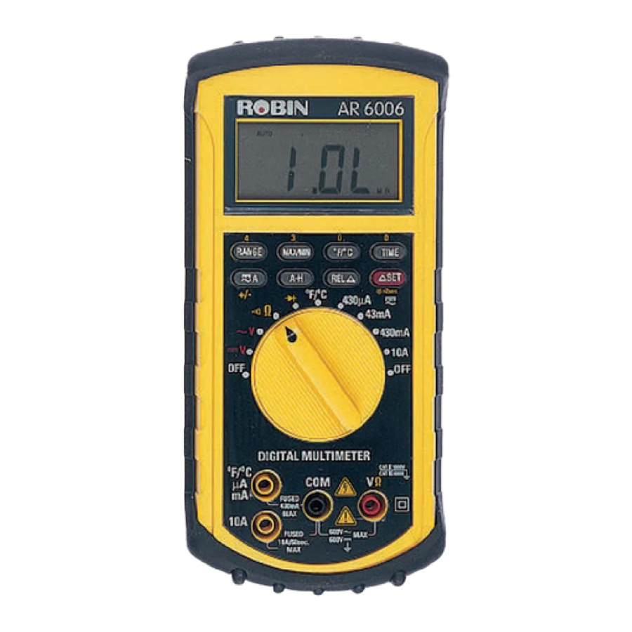
Robin AR6006 - Digital Multimeter Operating Manual
- Operating instructions (2 pages)
Advertisement
SAFETY INFORMATION
For measurements on Energised circuits Robin Electronics recommends the use of Fused test leads complying with the requirements of Standard GS38, to maximise user safety. Please contact Robin Electronics for further information.
The following safety information must be observed to ensure maximum personal safety during the operation of this meter:
- Do not use the meter if the meter or test leads look damaged, or if you suspect that the meter is not operating properly.
- Do not use this instrument outside the specifications quoted.
- Turn off power to the circuit under test before cutting, unsoldering, or breaking the circuit. Small amounts of current can be dangerous.
- Use caution when working above 60V dc or 30V ac rms. Such voltages pose a shock hazard.
- When Using the probes, keep your fingers behind the finger guards on the probes.
- Measuring voltage which exceeds the limits of the multimeter may damage the meter and expose the operator to a shock hazard. Always respect the meter voltage limits as stated on the front of the meter.
- If the meter is used in a manner not specified by the manufacturer, the protection provided the meter may be impaired.
- Refer all servicing and repairs to Robin Electronics.
DC VOLTS
Ranges: 430mV, 4.3V, 43V, 430V, 600V
Resolution: 100µV
Accuracy: ±(0.25%rdg + 1dgt)
Input impedance: >10MΩ
Overload protection: 600VDC or AC rms
AC VOLTS (50Hz-2KHz)
Ranges: 430mV, 4.3V, 43V, 430V, 600V
Resolution: 100µV
Accuracy: ±(% of reading+no. of digits)
| Range | 50Hz~100Hz | 100Hz~500Hz | 500Hz~2KHz |
| 430mV | 1.5%+3dgts | N/A | N/A |
| 4.3V | ±0.75%+2dgts | ||
| 43V | |||
| 430V | ±1.5%+3dgts | ||
| 600V | |||
Input impedance: >10MΩ
Overload protection: 600VDC or AC rms
SPECIFICATIONS
Display: Liquid crystal display (LCD) with a maximum reading of 4300.
Polarity: Automatic, positive implied, negative polarity indication.
Overrange: "1 OL"or "-1 OL" is displayed.
Low battery indication: The " " is displayed when the battery voltage drops below the operating level.
Measurement rate: 2.5 times per second, nominal.
Operating Environment: 0°C to 40°C at < 70% relative humidity.
Storage Temperature: -20°C to 60°C, 0 to 80% R.H. with battery removed from meter.
Accuracy: Stated accuracy at 23°C ± 5°C, <75% relative humidity.
Safety: According to EN61010-1 protection class III overvoltage category (CAT III 600V) pollution degree 2.
For Indoor use only
Altitude: UP to 2000m.
Auto Power off: 30 minutes after last rotary switch or push button operation. (except MAX/MIN function)
Power: single standard 9-volt battery, NEDA 1604, JIS 006P, IEC 6F22.
Battery life: 200 hours typical with carbon-zinc.
Dimensions: 192mm (H) x 91mm (W) x 52.5mm (D).
Weight: 425g including battery.
Accessories: One pair test leads, One spare fuse installed, 9V battery (installed) and Operating Instructions.
10A fuse - Dimensions: 32mm long x 6.3mm dia. Breaking Capacity: 50KA
2A fuse - Dimensions: 32mm long x 6.35mm dia. Breaking Capacity: 50KA
DC CURRENT
Ranges: 430µA, 43mA, 430mA, 10A
Resolution: 100nA
Accuracy: ±(0.5%rdg + 1dgt) on µA,mA ranges
±(2.0%rdg + 1dgt) on 10A range
Burden voltage: 1.4V on all ranges, except 1.5V on 10A range
Input protection: 2A / 600V fast blow ceramic fuse
10A / 600V fast blow ceramic fuse
AC CURRENT (50Hz-1KHz)
Ranges: 430µA, 43mA, 430mA, 10A
Resolution: 100nA
Accuracy: ±(1.0%rdg + 2dgts) on µA,mA ranges
±(2.5%rdg + 2dgts) on 10A range
Burden voltage: 1.4V on all ranges, except 1.5V on 10A range
Input protection: 2A / 600V fast blow ceramic fuse
10A / 600V fast blow ceramic fuse
RESISTANCE
Ranges: 430Ω, 4.3KΩ, 43KΩ, 430KΩ, 4300KΩ, 43MΩ
Resolution: 100mΩ
Accuracy: ±(0.3%rdg + 3dgts) on 430Ω range
±(0.3%rdg + 2dgts) on 4.3KΩ to 4300KΩ ranges
±(1.5%rdg + 4dgts) on 43MΩ range
Audible indication: <50±30Ω
Open circuit volts: 0.4Vdc
Overload protection: 500VDC or AC rms
CONTINUITY
Audible indication: <50Ω±30Ω
Overload protection: 500VDC or AC rms
DIODE TEST
Accuracy: ±(3.0%rdg + 3dgts)
Resolution: 1mV
Test current: 1.0±0.6mA Test voltage: <3.5V
TEMPERATURE
Ranges: -20°C to 1300°C
-4°F to -2372°F
Resolution: 1°C, 2°F
Accuracy: ±(2.0%rdg + 3dgts) on -20°C to 500°C
±(3.0%rdg + 2dgts) on 500°C to 1300°C
±(2.0%rdg + 6dgts) on -4°F to 932°F
±(3.0%rdg + 4dgts) on 932°F to 2372°F
OPERATION
Before taking any measurements, read the Safety Information Section. Always examine the instrument for damage, contamination (excessive dirt, grease, etc.) and defects. Examine the test leads for cracked or frayed insulation. If any abnormal conditions exist do not attempt to make any measurements.
RANGE Button
Press (RANGE) button to select the Manual Range mode and turn off the "AUTO" annunciator.
In the Manual Range mode. Each time you press (RANGE) button, the range (and the input range annunciator) increments, and a new value is displayed. To exit the Manual Range mode and return to autoranging, press and hold down (RANGE) button for 2 seconds. The "AUTO" annunciator turns back on.
MAX/MIN Button
Press (MAX/MIN) to enter the MAX MIN AVG Recording mode (manual range only). The RECORD annunciator turns on and the automatic power-off feature is disabled.
Push (MAX/MIN) to cycle through the maximum(MAX), minimum(MIN), average(AVG) and present readings. Press and hold down the (MAX/MIN) for 2 seconds to exit and erase recorded reading.
A-H Button
In Auto hold mode, the meter will capture and hold the first stable non-zero (>100 digits) reading after a zero reading (<100 digits). Several consecutive measurements can be held and displayed without pressing the (A-H) button. Simply by shorting the test leads together between measurements.
Press (A-H) to toggle in and out of the Auto Hold mode.
In the Auto Hold mode, the A-H annunciator is displayed.
REL ∆ Button
Press (REL ∆) to enter the Relative mode, zero the display, and store the displayed reading as a reference value. The relative mode annunciator (∆) is displayed.
Press (REL ∆) again to exit the relative mode.
∆ SET and Back-Light Button
(![]() >2sec)
>2sec)
The Relative value can also be changed by the user.
To set the Relative value, press the (∆ SET) to enter the ∆ SET mode, relative value enter via yellow buttons (+/- 4300). Then press the (∆ SET) button, store the reference value.
Press (REL ∆) to enter the Relative mode, then press (∆ SET) to enter Relative set value as a reference value.
Press this button for 2 seconds to turn the Back-Light on. As this also activates the ∆ SET mode, briefly press the button to return to normal display.
To turn the Back-Light off press again for 2 seconds. The Back-Light will switch-off automatically after about 30 seconds.
TIME Button
Press (TIME) to enter elapsed-time mode.
Push (TIME) to cycle through the Minutes and seconds, hours and minutes.
Press and hold down the (TIME) for 2 seconds to exit TIME mode.
Voltage Measurements
- Connect the red test lead to the "VΩ" jack and the black test lead to the "COM" jack.
- Set the Function/Range switch to the desired voltage function.
- Connect the test leads to the device or circuit being measured.
- For dc, a (-) sign is displayed for negative polarity; positive polarity is implied.
Current Measurements
- Set the Function/Range switch to the desired current range and press the
![]() toggle button to select AC or DC.
toggle button to select AC or DC. - For current measurements less than 430mA, connect the red test lead to the µAmA jack and the black test lead to the COM jack.
- For current measurements of 430mA or greater, connect the red test lead to the 10A jack and the black test lead to the COM jack.
- Remove power from the circuit under test and open the normal circuit path where the measurement is to be taken. Connect the meter in series with the circuit.
- Use caution when measuring 10 amps on 10A range for 60s, always wait for 10 minutes before next measurement of 10 amps for safety reasons.
Resistance and Continuity Measurements
- Set the Function/Range switch to the resistance function.
- Remove power from the equipment under test.
- Connect the red test lead to the "VΩ" jack and the black test lead to the "COM" jack.
- Touch the probes to the test points. In ohms, the value indicated in the display is the measured value of resistance.
- The beeper sounds continuously, if the resistance is less than 50Ω±30Ω.

The accuracy of the functions might be slightly affected, when exposed to a radiated electromagnetic field environment, e.g., radio, telephone or similar.
Diode Tests
- Connect the red test lead to the "VΩ" jack and the black test lead to the "COM" jack.
- Set the Function/Range switch to the "
![]() " position.
" position. - Turn off power to the circuit under test.
- Touch probes to the diode. A forward-voltage drop is about 0.6V (typical for a silicon diode).
- Reverse probes. If the diode is good, 1 OL is displayed. If the diode is shorted, ".000" or another number is displayed.
- If the diode is open, 1 OL is displayed, in both directions.
- If the junction is measured in a circuit and a low reading is obtained with both lead connections, the junction may be shunted by a resistance of less than 1kΩ. In this case the diode must be disconnected from the circuit for accurate testing.
Temperature Measurements
- Set the Function/Range switch to the " °F/°C " position.
- Push the " °F/°C " key, select the desired °F/°C scale.
- Connect the temperature transition adaptor to the meter and make sure " + " and " - " polarity is correct.
- Connect a type K thermocouple to the jack on the transition adaptor. Place the probe or thermocouple tip on or in the material to be measured and take the temperature reading directly from the display.
MAINTENANCE
Remove test leads before changing battery or fuse or performing any servicing.
Battery Replacement
Power is supplied by a 9 volt "transistor" battery. (NEDA 1604, IEC 6F22). The "" appears on the LCD display when replacement is needed. To replace the battery, remove the two screws from the back of the meter and lift off the battery case. Remove the battery from battery contacts.
Fuse Replacement
If no current measurements are possible, check for a blown overload protection fuse. There are two fuses; F1 for the "mA" jack and F2 for the "10A" jack. For access to fuses, remove the four screws from the back of the meter and lift off the battery cover and case. Replace F1 only with the original type 2A/600V, fast acting ceramic fuse. Replace F2 only with the original type 10A/600V, fast acting ceramic fuse.
Servicing
Refer all service and repair to Robin Electronics. Do not attempt servicing or repair yourself. Robin Electronics recommend this instrument is calibrated at least once every 12 months. Contact Robin for a competitive quotation.
Cleaning
Periodically wipe the case with a damp cloth and detergent, do not use abrasives or solvents.
 | DANGEROUS VOLTAGE |  | SEE EXPLANATION IN MANUAL |
 | AC-ALTERNATING CURRENT |  | DOUBLE INSULATION (Protection Class II) |
 | DC-DIRECT CURRENT |  | GROUND |
International Electrical Symbols
Documents / ResourcesDownload manual
Here you can download full pdf version of manual, it may contain additional safety instructions, warranty information, FCC rules, etc.
Advertisement


Need help?
Do you have a question about the AR6006 and is the answer not in the manual?
Questions and answers