Table of Contents
Advertisement
Quick Links
¨
Thank you for purchasing the Hakko 470B Desoldering
Tool.
Please read the manual before using the Hakko 470B.
Store the manual in a safe, easily accessible place for
future reference.
CAUTION : Remove the pump securing screws (M4x25 marked red)
Desoldering Tool
Instruction Manual
from the bottom of the station.
Failure to do so may result in serious problems.
Table of Contents
Packing List··················································
Precautions··················································
(Desoldering Gun)··················
(Station)··································
Assembly and Connection)······
(Desoldering)························
(Cleaning during Operation)········
(Troubleshooting Guide)········
(Desoldering Gun)···········
(Station)···························
(Station)····························
(Desoldering Gun)················
Specifications, Wiring·······························
1
2
3
4
5·6
7·8
9
10
11
12~14
15·16
17·18
19·20
21
22
Advertisement
Table of Contents

Subscribe to Our Youtube Channel
Related Manuals for Hakko Electronics 470B


Summary of Contents for Hakko Electronics 470B
-
Page 1: Table Of Contents
Instruction Manual Thank you for purchasing the Hakko 470B Desoldering Tool. Please read the manual before using the Hakko 470B. Store the manual in a safe, easily accessible place for future reference. CAUTION : Remove the pump securing screws (M4x25 marked red) from the bottom of the station. -
Page 2: Packing List
Please check to make sure that all the items listed below Packing List are included in the Hakko 470B package. Station···················································· Ceramic Paper Filter (S)···································· Desoldering Gun···································· Ceramic Paper Filter (L)···································· Iron Holder Base···································· Spring Filter······················································· Spring Iron Holder·································· Cleaning Pin (for Ø1.0mm [0.04 in.] nozzle)······... -
Page 3: Precautions
·Advise those in the work area that the unit can reach very high temperatures and should be considered potentially dangerous. ·Turn the power OFF when no longer using the Hakko 470B or when leaving it unattended. ·Before replacing parts or storing the unit, allow the unit to cool and then turn the power OFF. -
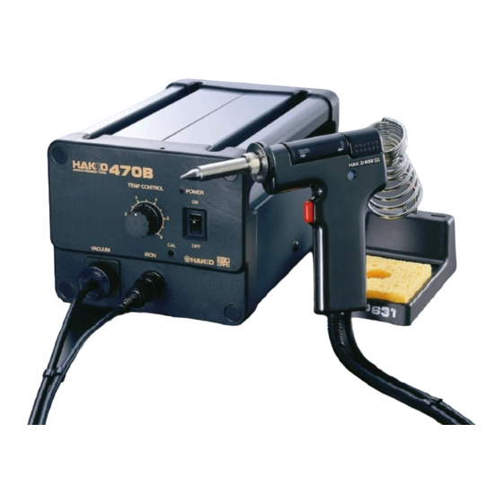
Page 4: Part Names (Desoldering Gun)
Part Names (Refer to p.19,20,21 for part nos.) Desoldering Gun Filter Pipe Nozzle Back Holder Set the ceramic paper filter (L) (No. A1033). Transmits heat for melting solder. Assembly Contains melted solder and flux using filters. Entrance for melted solder. Secures the filter Filter are expendable parts. -
Page 5: Station
Station Temperature Control Set Screw Clamp Temperature Control Knob Prevents the temperature Provides nozzle temperature control knob from being reset. control. (refer to p.7) (refer to p.7) Power Lamp Lights up when the power switch is turned to ON. Power Switch When turned to ON, the heating element starts to heat up. -
Page 6: Operation (Preparation-Assembly And Connection)
Operation Preparation–Assembly and Connection Assemble the Hakko 470B on a flat surface. Remove the pump securing Spring Iron Holder screws (M4x25 marked red) (No. B1094) from the bottom of the station. Cleaning Pin Holder (No. B1095) Assemble the iron holder. - Page 7 Connections CAUTION Be sure to turn the power switch off before connecting or disconnecting the cord assembly and the power plug. Failure to do so may damage the P.W.B. Insert the cord assembly by keying ·Connect the cord assembly to the plug to the key on the receptacle.
-
Page 8: Desoldering
·The temperature control knob can be secured by tightening the temperature control set screw clamp ("+ " screw) at the top of the Hakko 470B unit. Clean the tip of the nozzle. ·Keep the solder-plated section of the nozzle a shiny white by coating it with a small amount of solder. - Page 9 Melt the solder. ·Apply the nozzle to the soldered part and melt the solder. Nozzle CAUTION Never allow the nozzle to touch the board itself. P.W.B. Solder ·Confirm that the solder is Lead melted. CAUTION To confirm that all the solder is melted, observe the inside of the hole and the backside of the P.W.B.
-
Page 10: Cleaning During Operation
Operation Heated solder and flux can cause oxides to form and adhere to the nozzle and the inside of the heating element. These oxides not only lower the heat conductivity, but can also clog the nozzle and heating element, resulting in a drop in suction efficiency. -
Page 11: Problems During Desoldering
Remove all solder from the inside of the nozzle and perform the following maintenance heating element. procedures immediately after using Clean the tip of the nozzle with the cleaning sponge, then coat the tip with a fresh layer of solder to protect the Hakko 470B unit. the solder plating. -
Page 12: Troubleshooting Guide
WARNING : If the power cord is damaged, it must be replaced by Troubleshooting Guide the manufacturer, its service agent or similarity qualified person in order to avoid personal injury or damage to the unit. Power lamp does not light up. ·... -
Page 13: Maintenance (Desoldering Gun)
Maintenance (Desoldering Gun) Properly maintained, the Hakko 470B desoldering gun should provide years of good service. Efficient desoldering depends upon the temperature, and the quality and quantity of the solder and flux. Perform the following service procedures as dictated by the conditions of the gunÕs usage. - Page 14 @Disassemble the heating Element Cover Heating Element element. CAUTION The heating element is very hot Nozzle during operation. Remove the nut with the attached spanner. @Clean out the hole in the Scrape away all oxidation from the hole in the heating element until heating element with the the cleaning pin passes cleanly through the hole.
- Page 15 Secure the filters. ·Attach the spring filter to the front holder. ·Attach the front holder to the filter pipe. CAUTION Be sure the front holder is correctly aligned. CAUTION Ceramic Paper Use the ceramic paper filter (L) for the Filter (L) filter pipe (gun).
-
Page 16: (Station)
Maintenance (Station) Cleaning the inside of the Filter Case Replace the ceramic VACUUM paper filter (No. A1009). Remove the ceramic paper filter and inspect it. If it is stiff with flux, replace it. Filter Retainer Remove the filter retainer and push out the ceramic Ceramic Paper paper filter. - Page 17 Cleaning the Pump WARNING Unplug the power cord before Rear Panel starting this procedure. Cover Disassemble the pump heads. ·Remove the rear panel. ·Remove the cover. Remove ·Remove the pump head from the screws. each side of the pump. Remove the cover screws.
-
Page 18: Replacement Parts
Replacement Parts Replacing the Heating Element CAUTION Unplug the power cord before starting this procedure. The resistance value of a working heating element is 2-4 at 23˚C(73˚F). If the value you get is outside this range, replace the heating element. Remove the Filter Pipe. - Page 19 Insert a new heating element and reassemble. (Heating element 24V-50W) Cover the glass tube on the connecting part. CAUTION Before reassembling enclosure, make sure connectors are completely Bend the lead covered by the glass tube. before inserting it. push in. Position the leads in groove and press them into place.
- Page 20 Parts List (Station) Note: Spare or repair parts do not include mounting screws, if they are not listed on the description. Screws must be ordered separately. Pan Head Screw Item No. Part No. Part Name Description with Washer M 4 x 8 (2) B1029 Vacuum Outlet Cap A1009...
-
Page 21: Parts List
Parts List (Desoldering Gun) Pan Head Screw (Sus) M 2.6 x 7(3) Tapping Screw M 3 x 5 Item No. Part No. Part Name Description A1011 Front Holder A1030 Spring Filter 10 pcs. A1033 Ceramic Paper Filter (L) 10 pcs. B1128 Filter Pipe With Front Holder &... - Page 22 Specifications • Replacement Parts Name HAKKO 470B Part No. Part. Name / Specification Power Consumption 110W A1002 Nozzle S Ø0.8 mm (0.03 in.) • Station A1003 Nozzle S Ø1.0 mm (0.04 in.) Part Name Station A1004 Nozzle Ø0.8 mm (0.03 in.)
- Page 23 ¨ HEAD OFFICE 4-5, SHIOKUSA 2-CHOME, NANIWA-KU, OSAKA, 556-0024 JAPAN TEL:+81-6-6561-3225 FAX:+81-6-6561-8466 OVERSEAS AFFILIATES U.S.A.: AMERICAN HAKKO PRODUCTS, INC. 25072 ANZA DR. SANTA CLARITA, CA 91355, U.S.A. TEL: (805) 294-0090 FAX: (805) 294-0096 Toll Free (800)88-HAKKO 4 2 5 5 6 www.
Need help?
Do you have a question about the 470B and is the answer not in the manual?
Questions and answers