
Related Manuals for Hunter BL Series

Summary of Contents for Hunter BL Series
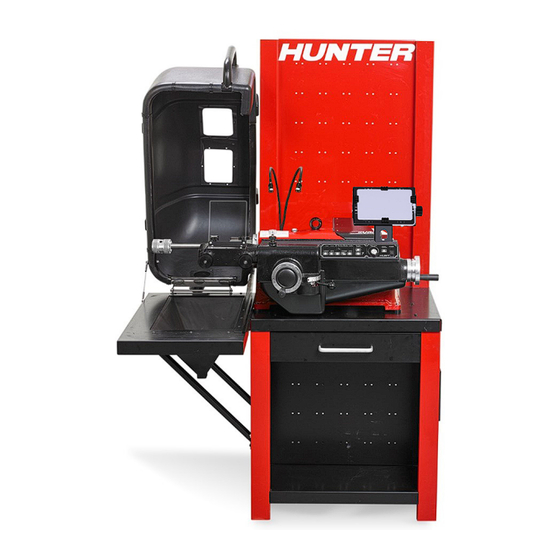
- Page 1 BL Series Drum / Disc Lathe 7674-T, 09-22 © Copyright 2019-2022 Hunter Engineering Company Page 1 of 30...
-
Page 2: Owner Information
BL Series Drum / Disc Lathe 1.1. Owner Information Page 2 of 30... -
Page 3: Getting Started
The owner of the BL Series brake lathe is solely responsible for arranging technical training. The lathe is to be operated only by a qualified Hunter trained technician. Maintaining records of personnel trained is solely the responsibility of the owner or management. - Page 4 Maintain tools with care. Keep tools sharp and clean for best and safest performance. Follow instructions for lubricating and changing accessories. Use only Hunter recommended accessories. Consult the Brake Lathe Packages and Accessories Brochure Form 3947-T for recommended accessories. The use of non-recommended accessories may cause risk of injury to persons.
- Page 5 BL Series Drum / Disc Lathe Check for damaged parts. Before further use of the tool, a guard or other part that is damaged should be carefully checked to determine that it will operate properly and perform its intended function - check for alignment of moving parts, binding of moving parts, breakage of parts, mounting, and any other conditions that may affect its operation.
-
Page 6: Operation Information
BL Series Drum / Disc Lathe Use only 3-wire extension cords that have 3-prong grounding plugs and 3-pole receptacles that accept the tool’s plug. Repair or replace damaged or worn cords immediately. The Lathe is intended for use on all grounded supply circuits having a nominal rating less than 110VAC or 220VAC. - Page 7 BL Series Drum / Disc Lathe Disc Tool Bit Micrometer Controls Disc tool bit micrometer controls are used to make accurate cutting insert depth adjustments. Rotating the controls clockwise feeds the cutting inserts into the disc friction surface, rotating the controls counter...
- Page 8 BL Series Drum / Disc Lathe “FEED RATE” dial is used to change feed rate from slow to fast. Slow is labeled as FINE. Fast is labeled as COURSE. The recommended range of feed rates for One Cut Pass is also specified. One Cut operation is the method of cutting a drum or disc in which, a single cut is used to remove friction surface material and provide the desired finish.
- Page 9 BL Series Drum / Disc Lathe Hubless Discs and Drums Care should be taken to ensure the following: All contact surfaces on the arbor, the centering cone, and the adaptors are clean. Verify that the centering cone and the adaptors are free of nicks and burrs. If the contact surfaces are not smooth, flat, and making full contact, sand with fine emery cloth or replace.
- Page 10 BL Series Drum / Disc Lathe Verify that the arbor runout is no more than .0015 inch (.381 mm). The arbor should be cleaned prior to installing. If the arbor is bent, replace with a new one. Verify that the mounting surfaces on the disc are clean and free of any high spots. These high spots may be eliminated by filing.
- Page 11 BL Series Drum / Disc Lathe 1.3.4. Disc Resurfacing Measure the total indicated runout to determine the deepest cut necessary toresurface the disc. Refer to “2.7 Measuring Total Indicated Runout (T.I.R.)” onpage 17. Page 11 of 30...
- Page 12 BL Series Drum / Disc Lathe Page 12 of 30...
- Page 13 BL Series Drum / Disc Lathe 1. Choose the proper spindle speed. Refer to “2.3 Spindle Speed Adjustment” onpage 9. 2. Using a micrometer, check the thickness / parallelism of the disc from at least three points around the circumference, about 1 inch (25 mm) in from the outer diameter. If the disc thickness variation is out of specification, it should be machined.
- Page 14 BL Series Drum / Disc Lathe 22. Turn the power switch to “OFF.” 23. Remove the disc from the arbor and clean with brake cleaner or warm soapy water. 1.3.5. Drum Resurfacing Check the setup and workpiece accuracy. Refer to “2.6 Achieving SetupAccuracy and Determining Work- piece Quality/Condition”...
- Page 15 BL Series Drum / Disc Lathe 1. Choose the proper spindle speed. Refer to “2.3 Spindle Speed Adjustment” onpage 9. 2. Using a brake drum diameter gauge, check the drum diameter from at least three points around the circumference, about 1 inch (25 mm) in from the outer diameter. If the drum diameter is greater than the maximum diameter established by the manufacturer, or if it will be greater after surfacing, the drum should be replaced.
- Page 16 BL Series Drum / Disc Lathe 1. Determine if there is excess setup runout by inserting the box end of the5/16 inch (8 mm) wrench, 221-604-2 (provided with lathe), into the center drill end of the arbor while the spindle is turning and lightly hold the opposite end.
- Page 17 BL Series Drum / Disc Lathe 1.3.7. Measuring Total Indicated Runout (T.I.R.) 1. Feed the cutting insert in until it just scratches the surface. 2. Zero the depth-of-cut micrometer dial. 3. Find the maximum permissible runout for the vehicle being serviced. This value will be .003 inch (.762 mm) to .005 inch (1.27 mm) for most vehicles.
- Page 18 BL Series Drum / Disc Lathe Pressing “ZERO” button set current position to 0.0000. Pressing “CAL” button starts calibration mode. Pressing “TOGGLE DISP” button toggles between three different display modes asindicated by the green LED next to DRUM or ROTOR located above the numbersand the green LEDs next to DIAMETER, THICK- NESS or DEPTH below the numbers:.
-
Page 19: Prepare For Calibration
BL Series Drum / Disc Lathe Prepare for Calibration 1. Connect the BL power cord to an AC outlet. 2. Verify that the BL power switch is in the "OFF" position. 3. Locate the supplied calibration tool, 25-115-1. 4. Locate the "CAL" button and both "ZERO" button on the Digi-Cal unit. - Page 20 BL Series Drum / Disc Lathe 1. Press the “CAL” button on the DigiCal unit. 2. Display will now show “CAL” and “rot” on the Digi-Cal displays, indicating it is ready for disc thickness calibration. 3. Move the twin cutter to the disc cutting position..
-
Page 21: Preliminary Steps
BL Series Drum / Disc Lathe - The potential for removing too much material from the disc. Preliminary Steps Preliminary Steps 1. With the disc mounted on the spindle, position the twin cutter so the cutting inserts are oneither side of the disc. -
Page 22: Setting Depth-Of-Cut
BL Series Drum / Disc Lathe Measuring Non-Grooved Disc Thickness 1. Position the cutting inserts at the inner diameter of the inboard and outboard friction surfaces of the disc. 2. Turn both disc micrometer control knobs until each insert just scratches the disc. - Page 23 BL Series Drum / Disc Lathe With the data provided by the Digi-Cal, the technician can determine the necessaryamount of material to remove from the drum for a one-cut resurfacing operation, orreplace the drum if it is oversized. Using this unique procedure, the Digi-Cal can measure and combine the deepest wear point on the drum, with total indicated runout (T.I.R.), to calculate the true maximum drum diameter.
-
Page 24: Equipment Maintenance
BL Series Drum / Disc Lathe Measuring Non-Grooved Drum Diameter Measuring Non-Grooved Drum DiameterAllow the cutting insert to travel past the outer edge of the drum. 1. Position the cutting insert at the inner diameter of the drum friction surface. - Page 25 BL Series Drum / Disc Lathe • Lubricate the main support shaft once per year. The grease fitting is located on the left side of the main housing. • Lubricate the drum boring bar once per year. The grease fitting is located on the underside of the feed housing, inside the lower cover.
-
Page 26: Workpiece Preparation
BL Series Drum / Disc Lathe Removal 1. Loosen the drawbar 7/8 inch hex until the taper “pops." 2. Continue turning the 7/8 inch hex by hand to remove the arbor. 1.5.3. Verifying Adaptor Integrity All clamp cups, spacers, cones, split collets, and adaptors used for mounting drums and discs must have all mating surfaces smooth and perpendicular to the spindle shaft. -
Page 27: Installation
BL Series Drum / Disc Lathe Removal 1. Disconnect the lathe AC power cord from the outlet. 2. Loosen and remove the #4-40 X 1/4 inch flat head screw securing the cutting insertto the insert holder. 3. Remove the cutting insert. - Page 28 BL Series Drum / Disc Lathe SYMPTOM PROBABLE CAUSE SOLUTION Excess Work- Arbor nut too tight It is not recommended to use a wrench to tighten the workpiece. HAND piece Runout TIGHTEN ONLY Dirty or warped workpiece All rust, grease and dirt must becleaned from mounting surfacesof the work- Dirty or dinged adaptors piece.
- Page 29 BL Series Drum / Disc Lathe Hubless Adaptor A mounting accessory that is used to mount hubless discs. It can be faster to use than clamp cups and a centering cone. Hubless Disc A disc that does not contain bearing races.
-
Page 30: Warranty Information
(6) months machine warranty are warranted for a period of six (6) month In case of any warranty claim, it will be necessary to contact your local authorized Hunter Service Represen- tative. To have an item considered for warranty, it must be returned to Hunter Engineering Company for inspection and evaluation.
Need help?
Do you have a question about the BL Series and is the answer not in the manual?
Questions and answers
what is the type of oil which is used in this machine
The type of oil used in the Hunter BL Series machine is not specified in the provided context.
This answer is automatically generated