
Subscribe to Our Youtube Channel
Related Manuals for Banner T30RW


Summary of Contents for Banner T30RW
- Page 1 T30RW R-GAGE Washdown Radar Sensor Instruction Manual Original Instructions p/n: 232729 Rev. B June 23, 2023 © Banner Engineering Corp. All rights reserved.
-
Page 2: Table Of Contents
Contents Contents ..........................2 Chapter 1 T30RW Product Description T30RW Models ......................................5 T30RW Overview ......................................6 T30RW Features and Indicators .................................. 6 Signal Strength and the Indicator LEDs ............................... 6 Radar Configuration Software ..................................7 Chapter 2 Installation Instructions Sensor Orientation ....................................... 9 Mount the Device Using the Threaded Barrel .............................. 9 T30R Wiring ....................................... - Page 3 Banner Engineering Corp. Software Copyright Notice ..........................41 Banner Engineering Corp Limited Warranty .............................. 41 ...
- Page 4 Blank page ...
-
Page 5: Chapter 1 T30Rw Product Description
(off) output condition. T30RW Models NOTE: If there is a very strong radar target 50 m (164 ft) away or farther from the sensor, it could cause false detection inside of the sensing range. T30RW-1515 Models (15 x 15 degree beam pattern) Models Detection Range Barrel Thread Type ... -
Page 6: T30Rw Overview
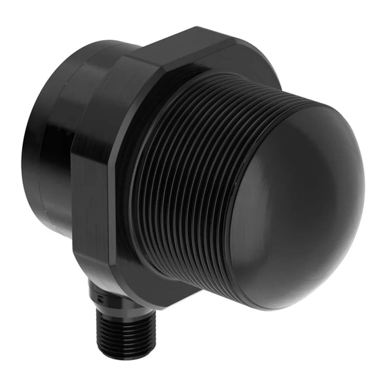
T30RW R-GAGE Washdown Radar Sensor Instruction Manual T30RW Overview The T30RW is an industrial radar sensor that uses high-frequency radio waves from an internal antenna. It detects high- dielectric targets, such as metal or large amounts of water, and lower-dielectric materials, such as wood, rock, or organic material. The sensor can be configured with software, IO-Link, or remote input wires to sense objects up to a specific distance, ignoring objects beyond this distance (background suppression). -
Page 7: Radar Configuration Software
T30RW R-GAGE Washdown Radar Sensor Instruction Manual Radar Configuration Software Use Banner's Radar Configuration Software to: • Set up the sensor 3 easy steps: set the switch point distance, signal strength threshold, and response time • Easily monitor device status via the software •... - Page 8 Blank page ...
-
Page 9: Chapter 2 Installation Instructions
T30RW R-GAGE Washdown Radar Sensor Instruction Manual Chapter Contents Sensor Orientation ......................................9 Mount the Device Using the Threaded Barrel ..............................9 T30R Wiring ........................................10 Chapter 2 Installation Instructions Sensor Orientation Correct sensor-to-object orientation is important to ensure proper sensing. Minimize the tilt angle of a target relative to the sensor. The target should be tilted less than half of the beam angle. Tilt angle of the target relative to the sensor target θ... -
Page 10: T30R Wiring
T30RW R-GAGE Washdown Radar Sensor Instruction Manual T30R Wiring Quick disconnect wiring diagrams are functionally identical. Push-pull Output and Analog Current Output Push-pull Output and Analog Voltage Output 10–30 V DC 12–30 V DC – – D_Out/IO-Link Load Load D_Out/IO-Link A_Out A_Out 0-10 V... -
Page 11: Chapter 3 Getting Started
T30RW R-GAGE Washdown Radar Sensor Instruction Manual Chapter Contents Install the Software ......................................11 Connect to the Sensor......................................11 Software Overview ......................................12 Chapter 3 Getting Started Power up the sensor, and verify that the power LED is ON green. Install the Software IMPORTANT: Administrative rights are required to install the Banner Radar Configuration software. Download the latest version of the software from www.bannerengineering.com/us/en/products/sensors/software/ radar-configuration.html. Navigate to and open the downloaded file. Click Install to begin the installation process. Depending on your system settings, a popup window may appear prompting to allow Banner Radar Configuration to make changes to your computer. Click Yes. Click Close to exit the installer. ... -
Page 12: Software Overview
T30RW R-GAGE Washdown Radar Sensor Instruction Manual Select the correct Sensor Model and Com Port for the sensor. Click Connect. The Connection screen closes and the sensor data displays. Software Overview Easy setup and configuration of range, sensitivity, and output using the Banner Radar Configuration software and Pro Converter Cable. Banner Radar Configuration Software Navigation toolbar—Use this toolbar to connect to the sensor, to save or load a configuration, or to reset to factory defaults ... -
Page 13: Chapter 4 Banner Radar Configuration Workspace
T30RW R-GAGE Washdown Radar Sensor Instruction Manual Chapter Contents Navigation Toolbar ......................................13 Live Sensor Data and Legend ..................................13 Summary Pane ......................................... 14 Sensor Settings Pane......................................14 Live Sensor Data Controls ....................................17 Chapter 4 Banner Radar Configuration Workspace Navigation Toolbar Use this toolbar to connect to the sensor, to save or load a configuration, or to reset to factory defaults. ... -
Page 14: Summary Pane
T30RW R-GAGE Washdown Radar Sensor Instruction Manual Signal Displays the strength of the signal over distance. Signal Threshold Displays the signal strength threshold. Primary Targets Represents the signal strength and location of the strongest target inside the switch point. Analog Window The range the analog signal represents. Available on analog models. Varies by output model. Discrete 1/2 Window The range for the discrete output. Varies by output model. Switch Pt Lines Displays the switch point distance. Hysteresis Lines Displays the hysteresis distance. Summary Pane The Summary pane (blue shaded area) displays Distance, Signal Strength, and Output Status. Distance Displays the distance to the target. Signal Strength ... -
Page 15: Analog Tab
T30RW R-GAGE Washdown Radar Sensor Instruction Manual Advanced Target Minimum Active Sensing Range: Sensor ignores anything from the face of the sensor to this defined range. Maximum Active Sensing Range: Sensor ignores anything past this defined range. Measurement Hold: A rate of change filter to smooth the output and reduce chatter. For more information, see "Using Measurement Hold Example " on page 26. Hold Time: The period of time the sensor holds its last measurement and output status if the measurement changes more than the Maximum Distance Increase or the Maximum Distance Decrease. Available when Measurement Hold is ... -
Page 16: Discrete 1 Tab
T30RW R-GAGE Washdown Radar Sensor Instruction Manual Response Time Calculates the total response time, taking into account the general response speed and averaging. Analog Analog Output Filter Setting Response 1 2 4 8 16 32 64 128 Speed Analog Output Spec (ms) Fast 2 4 8 16 32 64 128 256 Medium 20 40 80 160 320 640 1280 ... -
Page 17: Live Sensor Data Controls
50 Hz or 650 Hz (user defined in the software) represents a loss of signal condition where there is no target or the target is out of range. This output can be tied directly to a number of Banner lights for visual feedback without the need for a controller. ... - Page 18 Blank page ...
-
Page 19: Chapter 5 Configuring A Sensor
Master AOI is to translate the desired IO-Link read/write requests, made by the Parameter Data AOI, into the format a specific IO-Link Master requires. Each IO-Link Master AOI is customized for a given brand of IO-Link Master. Add and configure the relevant Banner IO-Link Master AOI in your ladder logic program first; then add and configure Banner IO-Link Device AOIs as desired, linking them to the Master AOI as shown in the relevant AOI documentation. ... - Page 20 T30RW R-GAGE Washdown Radar Sensor Instruction Manual The remote input wire is disabled by default. Pulse the remote input wire 10 times or use the Banner Radar Configuration software to enable the feature. After enabling the remote input feature, pulse the remote input according to the diagram and the instructions provided in this manual. Remote teach can also be performed using the button on the Pro Converter Cable. The length of the individual programming pulses is equal to the value T: 0.04 seconds ≤ T ≤ 0.8 seconds. Exit remote programming modes by setting the remote input Low for longer than 2 seconds or by waiting for 60 seconds. June 23, 2023 © Banner Engineering Corp.
- Page 21 T30RW R-GAGE Washdown Radar Sensor Instruction Manual Remote Input Map Remote Input Gray wire is remote teach input Remote Setup Output 1 Mode/Slope (analog output for analog model, use discrete menu options below for dual discrete model) Positive Slope...
-
Page 22: Remote Teach
T30RW R-GAGE Washdown Radar Sensor Instruction Manual NOTE: If a factory reset is performed through the Banner Radar Configuration Software, the remote input wire becomes disabled (factory default setting). If the sensor is returned to factory defaults by using the remote input wire, the input wire remains enabled and the rest of the settings are restored to factory defaults. ... - Page 23 T30RW R-GAGE Washdown Radar Sensor Instruction Manual Analog Teach Modes The default is to teach two separate points. With a positive slope, the first taught point is 4 mA and the second taught point is 20 mA. If the two taught points are within 100 mm or less, the sensor views them as the same point. It considers that point as the 20 mA spot and sets the 4 mA spot at 300 mm. If a taught point is within the dead zone, the sensor sets that point at 300 mm. ...
- Page 24 T30RW R-GAGE Washdown Radar Sensor Instruction Manual Continued from page 23 Action Result Pulses TEACH Mode 8 Signal Strength Threshold = 30 Set the Speed Use Speed Selection to set the speed of the sensor. Access Speed Selection. Action Result Four-pulse the remote input. The green power LED flashes slowly. Select the desired signal threshold. Action Result Pulses TEACH Mode ...
-
Page 25: Reset The Sensor To Factory Defaults
To reset using the Banner Radar Configuration software, go to Sensor › Factory Reset. The sensor indicators flash once, the sensor is reset back to the factory default settings, and a confirmation message displays. -
Page 26: Using Measurement Hold Example
T30RW R-GAGE Washdown Radar Sensor Instruction Manual Continued from page 25 Setting Factory Default On Delay 0 ms Off Delay 500 ms Discrete 2 Tab Default Settings Setting Factory Default Output Mode Switch Point Setpoint 1 15.0 m (49.2 ft) Hysteresis 0.05 m (2 in) NO/NC Normally Open On Delay 0 ms Off Delay 500 ms Using Measurement Hold Example Measurement Hold (The hold time is set to 1 second) Raw Measurement... - Page 27 T30RW R-GAGE Washdown Radar Sensor Instruction Manual Continued from page 26 The Raw Measurement change (blue lines) is greater than the Max Distance Change (red lines) so the Output Measurement (green lines) holds its previous value while the Raw Measurement is beyond the Max Distance C. ...
- Page 28 Blank page ...
-
Page 29: Chapter 6 T30Rw Specifications
T30RW R-GAGE Washdown Radar Sensor Instruction Manual Chapter Contents FCC Part 15 Class A ......................................30 Industry Canada Statement for Intentional Radiators ............................30 T30RW Dimensions ......................................31 T30RW Beam Patterns ....................................32 Chapter 6 T30RW Specifications Range Response Time The sensor can detect an object at the following ranges, Analog update rate: 2 ms depending on the material of the target: ... -
Page 30: Fcc Part 15 Class A
T30RW R-GAGE Washdown Radar Sensor Instruction Manual Continued from page 29 Output Ratings Analog Outputs: Black wire specifications per configuration · Current Output (T30R….-.I.. models): 1 kΩ maximum load Output Low ≤ 2.5 V resistance at 24 V; maximum load resistance = [(Vcc - 4.5)/ 0.02 Ω] · Voltage Output (T30R….-.U.. models): 2.5 kΩ minimum load White wire specifications per configuration resistance Output High ≥ Vsupply - 2.5 V Discrete Outputs: PNP · Current rating = 50 mA maximum each Output Low ... -
Page 31: T30Rw Dimensions
T30RW R-GAGE Washdown Radar Sensor Instruction Manual Cet appareil contient des émetteurs/récepteurs exemptés de licence conformes à la norme Innovation, Sciences, et Développement économique Canada. L’exploitation est autorisée aux deux conditions suivantes: L’appareil ne doit pas produire de brouillage. L’utilisateur de l’appareil doit accepter tout brouillage radioélectrique subi, même si le brouillage est susceptible d’en compromettre le fonctionnement. T30RW Dimensions All measurements are listed in millimeters [inches], unless noted otherwise. T30RW-1515-KxQ-M40 Models 64.3... -
Page 32: T30Rw Beam Patterns
T30RW R-GAGE Washdown Radar Sensor Instruction Manual T30RW-1515-KxQ-NPT 1.5 Models R30 [1.18] T30RW Beam Patterns The beam pattern of the radar sensor is dependent on the radar cross section (RCS) of the target. The beam pattern graphs are guides for representative object detection capabilities based on different-sized radar cross- sections and corresponding example real-world targets. Use the following charts as a starting point in the application setup. - Page 33 T30RW R-GAGE Washdown Radar Sensor Instruction Manual Typical beam pattern, in meters, on representative targets Typical beam pattern, in degrees, on representative targets Car (Radar cross section = 6 m 2 ) Car (Radar cross section = 6 m 2 ) Distance (m) Distance (m) June 23, 2023 © Banner Engineering Corp.
- Page 34 Blank page ...
-
Page 35: Chapter 7 Update The Software
T30RW R-GAGE Washdown Radar Sensor Instruction Manual Chapter Contents Chapter 7 Update the Software Use this procedure to update the Banner Radar Configuration Software. The Banner Radar Configuration Software automatically looks for updated software versions. The symbol in the lower right corner indicates that a software update is available. Software Update Available Click in the lower right corner of the software. The Banner Radar Configuration Software Update screen displays. Banner Radar Configuration Software Update Screen Click Upgrade to begin the process. ... - Page 36 Blank page ...
-
Page 37: Chapter 8 Accessories
T30RW R-GAGE Washdown Radar Sensor Instruction Manual Chapter Contents Brackets ........................................... 37 Cordsets ........................................... 37 Configuration Tool ......................................39 Chapter 8 Accessories Brackets All measurements are listed in millimeters, unless noted otherwise. SMB40A • Right-angle bracket with curved slot for versatile orientation Ø40.75 • Clearance for M6 (¼ in) hardware 2X Ø6.35 •... - Page 38 T30RW R-GAGE Washdown Radar Sensor Instruction Manual 5-Pin Threaded M12 Cordsets with Shield—Single Ended Model Length Style Dimensions Pinout (Female) MQDEC2-506 2 m (6.56 ft) 44 Typ. MQDEC2-515 5 m (16.4 ft) MQDEC2-530 9 m (29.5 ft) Straight MQDEC2-550 15 m (49.2 ft) M12 x 1 ø 14.5 MQDEC2-575 23 m (75.44 ft) MQDEC2-5100 30.5 m (100 ft) 32 Typ. MQDEC2-506RA 2 m (6.56 ft) 1 = Brown ...
-
Page 39: Configuration Tool
T30RW R-GAGE Washdown Radar Sensor Instruction Manual Configuration Tool PRO-KIT Includes: • Pro Converter Cable (MQDC-506-USB) • Splitter (CSB-M1251FM1251M) • Power Supply (PSW-24-1) June 23, 2023 © Banner Engineering Corp. - Page 40 Blank page ...
-
Page 41: Chapter 9 Product Support And Maintenance
Banner and its affiliates and channel partners do not warrant that the services are secure, free from bugs, viruses, interruption, errors, theft or destruction. If the exclusions for implied warranties do not apply to you, any implied warranties are limited to 60 days from the date of first use of this software. ... - Page 42 WHETHER ARISING IN CONTRACT OR WARRANTY, STATUTE, TORT, STRICT LIABILITY, NEGLIGENCE, OR OTHERWISE. Banner Engineering Corp. reserves the right to change, modify or improve the design of the product without assuming any obligations or liabilities relating to any product previously manufactured by Banner Engineering Corp. Any misuse, abuse, or improper application or installation of this product or use of the product for personal protection applications when the product is identified as not intended for such purposes will void the product warranty.
- Page 43 LinkedIn Twitter Facebook © 2023. All rights reserved. www.bannerengineering.com...
Need help?
Do you have a question about the T30RW and is the answer not in the manual?
Questions and answers