Table of Contents
Advertisement
Available languages
Available languages
Quick Links
DS1760-009A
(bianco / white / blanc / blanco / weiß / wit)
(nero / black / noire / negro / schwarz / zwart)
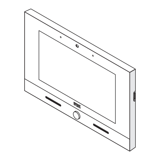
VIDEOCITOFONO 7"
VIDEO DOOR PHONE 7"
MONITEUR 7"
VIDEOINTERFONO 7"
7"-VIDEOSPRECHANLAGE
7"-BEELDINTERCOM
Sch./Ref. 1760/31 - 1760/31A
Sch./Ref. 1760/33 - 1760/33A
LIBRETTO INSTALLAZIONE
INSTALLATION HANDBOOK
NOTICE D'INSTALLATION
MANUAL DE INSTALACIÓN
INSTALLATIONSANLEITUNG
INSTALLATIEHANDLEIDING
Mod.
1760
LBT21058
Advertisement
Table of Contents

Related Manuals for urmet domus VOG 7 1760


Summary of Contents for urmet domus VOG 7 1760
- Page 1 Mod. 1760 DS1760-009A LBT21058 VIDEOCITOFONO 7” VIDEO DOOR PHONE 7” MONITEUR 7” VIDEOINTERFONO 7” 7”-VIDEOSPRECHANLAGE 7”-BEELDINTERCOM Sch./Ref. 1760/31 - 1760/31A (bianco / white / blanc / blanco / weiß / wit) Sch./Ref. 1760/33 - 1760/33A (nero / black / noire / negro / schwarz / zwart) LIBRETTO INSTALLAZIONE INSTALLATION HANDBOOK NOTICE D’INSTALLATION...
-
Page 2: Descrizione Generale
ITALIANO 1. DESCRIZIONE GENERALE Il videocitofono Sch.1760/31 o /33, è un dispositivo dedicato al sistema 2Voice che può operare come: • Videocitofono evoluto • Terminale domotico Yokis • Terminale per la visualizzazione delle telecamere di videosorveglianza • Terminale per la visualizzazione dello stato della centrale antintrusione •... -
Page 3: Installazione
9. Chiavistello di blocco del videocitofono 10. Dip-switch di configurazione (SW1 / SW2): n. 1 di SW1, se impostato su ON, abilita il parametro “Accensione contemporanea” che permette ai videocitofoni presenti nell’appartamento di accendersi contemporaneamente alla ricezione di una chiamata da postazione di chiamata. La prestazione è disponibile se tutti i videocitofoni presenti in un appartamento: –... -
Page 4: Descrizione Dei Morsetti
• Utilizzare un cacciavite per spostare da sinistra verso destra il chiavistello che permette il blocco del videocitofono sulla staffa. • Rimuovere la pellicola di protezione dal display. 3.1. DESCRIZIONE DEI MORSETTI Morsettiera sinistra Positivo per suoneria supplementare Negativo per suoneria supplementare Chiamata al piano Comune per allarme panico, input allarme 1 e input allarme 2 PANIC... - Page 5 4. INSERIMENTO CONTATTI PER CHIAMATE INTERCOMUNICANTI Per poter effettuare delle chiamate intercomunicanti è necessario inserire dei contatti nella rubrica videocitofonica. È possibile inserire fino a 32 contatti direttamente dal videocitofono. Tramite l’applicazione 2Voice Installer Tools è possibile inserire ulteriori 32 contatti nella rubrica videocitofonica gestiti dall’applicazione. Per tutte le informazioni sull’inserimento dei contatti tramite l’applicazione, scansionare il QR Code presente all’ultima pagina del seguente libretto e scaricare il Libretto d’uso dell’app 2Voice Installer Tools.
- Page 6 • Si apre la schermata di richiesta di inserimento di un nuovo contatto. Tipologia di contatto Selezionare la seguente icona per modificare la tipologia di contatto. • Contatto esterno: chiamata a un videocitofono presente in un altro appartamento ma all’interno della stessa colonna videocitofonica •...
- Page 7 5. RESET AI PARAMETRI DI FABBRICA Il reset alle impostazioni di fabbrica cancella tutte le configurazioni effettuate sul videocitofono. Per eseguire il reset alle impostazioni di fabbrica seguire la seguente procedura: • Accendere lo schermo, se spento, toccandolo in un punto qualsiasi o premendo il tasto Home. • Premere l’icona per accedere alla Top Page. •...
- Page 8 Scorrere i parametri e premere sulla voce Manutenezione per visualizzare le funzioni e i parametri di • manutenzione del videocitofono. Reset Impostazioni di Fabbrica. • All’interno del menu premere sulla voce Sullo schermo viene visualizzata una finestra pop-up di conferma dell’operazione. Premere il pulsante SI per effettuare l’operazione e cancellare tutte le configurazioni presenti nel •...
-
Page 9: Caratteristiche Tecniche
6. CARATTERISTICHE TECNICHE Tensione di alimentazione (LINE IN): ....................36 ÷ 48 V Assorbimento (LINE IN): ........................@ 48 V Riposo: ............................. < 2 mA A regime: ............................< 15 mA Tensione di alimentazione (V+, V-): ......................24 V~ Assorbimento (V+, V-): ........................@ 24 V~ Riposo: ...........................<... -
Page 10: General Description
ENGLISH 1. GENERAL DESCRIPTION The video door phone Ref. 1760/31 or /33, is a device dedicated to the 2Voice system which can operate as: • Cutting-edge video door phone • Yokis building automation terminal • Terminal for displaying the video surveillance cameras •... -
Page 11: Installation
10. Configuration dip-switch (SW1 / SW2): – no.1 of SW1, if set to ON, it enables the “Simultaneous ignition“ parameter which allows the video door phones in the apartment to switch on at the same time as they receive a call from the calling station. -
Page 12: Terminal Description
• Use a screwdriver to move the latch for locking the video door phone to the bracket from left to right. • Remove the protective film from the display. 3.1. TERMINAL DESCRIPTION Left terminal board Positive for additional chime Negative for additional chime Floor call Common for panic alarm, alarm 1 input and alarm 2 input PANIC Panic alarm Alarm 1 input (intrusion alarm indication) - Page 13 4. CONTACT INSERTION FOR INTERCOM CALLS In order to make intercom calls, it is necessary to enter contacts in the video door phone directory. Up to 32 contacts can be entered directly from the video door phone as follows. Using the 2Voice Installer Tools app, it is possible to add 32 additional contacts to the video door phone directory managed by the application.
- Page 14 • The request screen for entering a new contact opens. Contact type Select the following icon to modify the contact type. • External contact: call to a video door phone in another apartment but within the same video door phone riser •...
-
Page 15: Reset To Factory Settings
5. RESET TO FACTORY SETTINGS The reset to factory settings deletes all configurations made on the video door phone. To reset to factory settings, proceed as follows: • Turn on the screen, if off, by tapping it anywhere or by pressing the Home key. • Press the icon to access the Top Page. • Press the icon to access the video door phone parameter configuration page. DS1760-009A... - Page 16 Press on the Maintenance item to display the maintenance functions and parameters of the video door • phone. In the menu, press Reset Factory Settings. • A pop-up window is displayed on the screen to confirm operation. Press the YES button to perform the operation and delete all the configurations in the video door phone • and return it to the factory default configuration. Press the NO button to cancel the operation and close the pop-up window.
-
Page 17: Technical Specifications
6. TECHNICAL SPECIFICATIONS Power voltage (LINE IN): ........................36 ÷ 48 V Consumption (LINE IN): ........................@ 48 V Standby: ............................< 2 mA Full rate: ............................< 15 mA Power voltage (V+, V-): ..........................24 V~ Consumption (V+; V-): ........................@ 24 V~ Standby: ..........................<... -
Page 18: Description Générale
FRANÇAIS 1. DESCRIPTION GÉNÉRALE Le moniteur Réf.1760/31 ou /33 est un dispositif dédié au système 2Voice pouvant fonctionner en tant que : • Moniteur évolué • Terminal domotique Yokis • Terminal pour la visualisation des caméras de surveillance • Terminal pour la visualisation de l’état de la centrale anti-intrusion •... - Page 19 10. Commutateur DIP de configuration (SW1 / SW2): – n.1 de SW1, s’il est réglé sur ON, il active le paramètre “Allumage simultané“ qui permet aux moniteurs de l’appartement de s’allumer en même temps qu’ils reçoivent un appel du poste appelant. La fonction est disponible si les moniteurs installés dans l’appartement : –...
-
Page 20: Description Des Bornes
• À l’aide d’un tournevis, déplacer de gauche à droite le verrou de blocage du moniteur sur l’étrier. • Retirer le film de protection de l’afficheur. 3.1. DESCRIPTION DES BORNES Bornier gauche Positive pour sonnerie supplémentaire Négative pour sonnerie supplémentaire Appel a l’étage Commune pour alarme panique, entrée alarme 1 et entrée alarme 2 PANIC Alarme de panique Entrée alarme 1 (signalisation alarme intrusion) - Page 21 4. INSERTION DES CONTACTS POUR APPELS INTERCOMMUNICANTS Afin d’effectuer des appels intercommunicants, il faut saisir les contacts dans le répertoire du vidéophone. Il est possible de saisir jusqu’à 32 contacts directement depuis le vidéophone. Au moyen de l’application 2Voice Installer Tools, il est possible d’ajouter 32 contacts supplémentaires dans le répertoire du vidéophone gérés par l’application. Pour toutes les informations concernant la saisie des contacts via l’application, scanner le code QR figurant dans la dernière page du présent manuel et télécharger le Notice d’utilisation de l’App 2Voice Installer Tools.
- Page 22 • La page-écran de demande d’insertion d’un nouveau contact s’ouvre. Typologie de contact Sélectionner l’icône suivante pour modifier la typologie de contact. • Contact externe : appel à un moniteur installé dans un autre appartement mais à l’intérieur de la même colonne de vidéophonie • Contact interne : appel à...
- Page 23 5. RAZ AUX PARAMÈTRES D’USINE La raz aux paramètres d’usine supprime toutes les configurations effectuées sur le moniteur. Pour effectuer la raz aux paramètres d’usine, suivre la procédure ci-dessous : • Allumer l’écran, s’il est éteint, en le touchant dans un point quelconque ou en appuyant sur la touche Home. • Appuyer sur l’icône pour accéder à la Top Page. • Appuyer sur l’icône pour accéder à la page de configuration des paramètres du moniteur.
- Page 24 Faire défiler les paramètres et appuyer sur l’option Maintenance pour afficher les fonctions et les • paramètres de maintenance du moniteur. Appuyer sur l’option Raz paramètres d’usine du menu. L’écran visualise une fenêtre info-bulle de • confirmation de l’opération. Appuyer sur le bouton OUI pour effectuer l’opération et supprimer tous les réglages du moniteur en •...
-
Page 25: Caractéristiques Techniques
6. CARACTÉRISTIQUES TECHNIQUES Tension d’alimentation (LINE IN): ....................36 ÷ 48 V Consommation Maximum (LINE IN): ....................@ 48 V Au repos: ............................< 2 mA A plein régime: ..........................< 15 mA Tension d’alimentation (V+, V-): ......................24 V~ Consommation Maximum (V+; V-): ....................@ 24 V~ Au repos: ..........................<... -
Page 26: Descripción De Los Componentes
ESPAÑOL 1. DESCRIPCIÓN GÉNÉRALE El videointerfono Sch.1760/31 o /33, es un dispositivo dedicado al sistema 2Voice que puede funcionar como: • Videointerfono avanzado • Terminal de domótica Yokis • Terminal para ver las cámaras de videovigilancia • Terminal para ver el estado de la central antirrobo •... -
Page 27: Instalación
10. Interruptor dip de configuración (SW1 / SW2): – n.º 1 de SW1, si está configurado en ON, habilita el parámetro “Encendido simultáneo“ que permite que los videointerfonos de la vivienda se enciendan al mismo tiempo que reciben una llamada del puesto que llama. La prestación está disponible si los videointerfonos presentes en un apartamento: – han sido conectados directamente a la entrada LINE 1 ÷ 4 de un distribuidor vídeo Ref. 1083/55 –... - Page 28 • Utilizar un destornillador para desplazar de izquierda a derecha la clavija que permite el bloqueo del videointerfono en el soporte. • Retirar la película de protección de la pantalla. 3.1. DESCRIPCIÓN DE LOS BORNES Regleta de bornes izquierda Positivo para timbre adicional Negativo para timbre adicional Llamada al piso Común para alarma pánico, entrada alarma 1 y entrada alarma 2...
- Page 29 4. AGREGAR CONTACTOS PARA LLAMADAS INTERCOMUNICANTES Para poder realizar llamadas intercomunicantes es necesario agregar los contactos en la guía videointerfono. Se pueden agregar hasta 32 contactos directamente desde el videoportero. Mediante la aplicación 2Voice Installer Tools se pueden introducir 32 contactos adicionales en la agenda de videoportero gestionados por la aplicación.
- Page 30 • Se abre la pantalla para la introducción de un nuevo contacto. Tipo de contacto Seleccionar el icono para modificar el tipo de contacto. • Contacto externo: llamada a un videointerfono presente en otro apartamento pero en la misma columna de videointerfonos • Contacto interno: llamada a un videoportero presente en el mismo apartamento Código ID del videointerfono Seleccionar el cuadro de texto para escribir el código ID del videointerfono.
- Page 31 5. RESTABLECIMIENTO DE LOS PARÁMETROS DE FÁBRICA El restablecimiento de la configuración de fábrica elimina todos los ajustes hechos en el videointerfono. Para efectuar el restablecimiento, seguir este procedimiento: • Encender la pantalla, si está apagada, tocándola en un punto cualquiera o pulsando el botón de inicio. • Pulsar el icono para abrir la Top Page. •...
- Page 32 Desplazarse por los parámetros y pulsar Mantenimiento para ver las funciones y los parámetros de • mantenimiento del videointerfono. En el menú, pulsar la opción Restablecimiento configuración de fábrica. La pantalla muestra una • ventana emergente para confirmar la operación. Pulsar el pulsador SÍ para realizar la operación, eliminar todas las configuraciones del videointerfono • y restablecer la configuración de fábrica. Pulsar el pulsador NO para cancelar la operación y cerrar la ventana emergente.
-
Page 33: Características Técnicas
6. CARACTERÍSTICAS TÉCNICAS Tensión de alimentación (LINE IN): ....................36 ÷ 48 V Consumo máximo (LINE IN): ......................@ 48 V En reposo: ............................< 2 mA A régimen: ............................< 15 mA Tensión de alimentación (V+, V-): ......................24 V~ Consumo máximo (V+;... -
Page 34: Beschreibung Der Komponenten
DEUTSCH 1. BESCHREIBUNG Die Videosprechanlage BN 1760/31 oder /33 ist ein für das System 2Voice bestimmtes Gerät, das darin verwendet werden kann als: • Weiterentwickelte Videosprechanlage • Endgerät für Hausautomation Yokis • Endgerät für die Anzeige der Kamerabilder der Videoüberwachung •... - Page 35 9. Sperrklinke der Videosprechanlage 10. Konfigurations-Dip-Switch (SW1 / SW2): – 1 von SW1, bei Einstellung auf ON wird der Parameter “Gleichzeitiges Zündung“ aktiviert, der es den Video-Türsprechanlagen in der Wohnung ermöglicht, sich gleichzeitig einzuschalten, wenn sie einen Anruf von der Sprechstelle erhalten. Diese Funktion ist verfügbar, wenn die in einer Wohnung vorhandenen Videosprechanlagen: –...
- Page 36 • Einen Schraubenzieher verwenden, um die Sperrklinke von links nach rechts zu verschieben und so die Videosprechanlage an der Halterung festzustellen. • Die Schutzfolie vom Display entfernen. 3.1. BESCHREIBUNG DER KLEMMEN Klemmenleiste links Pluspol für zusätzliches Läutwerk Minuspol für zusätzliches Läutwerk Etagenruf Allgemein für Panikalarm 1, Eingang Alarm 1 und Eingang Alarm 2 PANIC...
- Page 37 4. EINGABE DER KONTAKTE FÜR INTERCOM-ANRUFE Zur Ausführung von Intercom-Anrufen muss man Kontakte in die Kontaktliste der Videosprechanlage eingeben. Es lassen sich bis zu 32 Kontakte eingeben direkt an der Videosprechanlage, indem wie folgt vorgegangen wird. Mit der Anwendung 2Voice Installer Tools können der von der Anwendung verwalteten Kontaktliste der Videosprechanlage 32 weitere Kontakte hinzugefügt werden.
- Page 38 • Die Anzeige für die Eingabe eines neuen Kontakts wird geöffnet. Kontakttyp Das folgendes Symbol markieren, um den Kontakttyp zu ändern. • Externer Kontakt: Anruf an eine Videosprechanlage, die sich in einer anderen Wohnung, jedoch innerhalb derselben Steigleitung der Videosprechanlage befindet • Interner Kontakt: Anruf an eine Videosprechanlage, die sich in derselben Wohnung befindet. ID-Nummer der Videosprechanlage Das Textfeld markieren, um die ID-Nummer der Videosprechanlage einzugeben. •...
- Page 39 5. RESET AUF WERKSPARAMETER Das Reset auf die werksseitig eingegebenen Einstellungen löscht alle bisher an der Videosprechanlage vorgenommen Konfigurationen. Beim Reset auf die werksseitigen Einstellungen wie folgt vorgehen: • Den Bildschirm durch Berühren eines beliebigen Punkts oder durch Drücken der Taste „Home“ einschalten.
- Page 40 Die Parameter durchscrollen und auf die Angabe Wartung drücken, um die Funktionen und die • Wartungsparameter der Videosprechanlage anzuzeigen. Im Menü auf die Angabe Reset Werkseinstellungen drücken. Am Bildschirm wird für die • Bestätigungsabfrage des Vorgangs ein Pop-up-Fenster eingeblendet. • Auf die Schaltfläche JA drücken, um den Vorgang durchzuführen und alle in der Videosprechanlage vorhandenen Konfigurationen zu löschen und so wieder auf die werksseitige Konfiguration zu setzen.
-
Page 41: Technische Eigenschaften
6. TECHNISCHE EIGENSCHAFTEN Versorgungsspannung (LINE IN): ....................36 ÷ 48 V Aufnahme (LINE IN): .......................... @ 48 V Ruhezustand: ............................ < 2 mA Bei Betrieb: ............................. < 15 mA Versorgungsspannung (V+, V-): ......................24 V~ Aufnahme (V+, V-): ..........................@ 24 V~ Ruhezustand: ..........................<... -
Page 42: Beschrijving Van De Componenten
NEDERLANDS 1. BESCHRIJVING De video-intercom Ref.1760/31 of /33, is een apparaat voor het systeem 2Voice dat kan werken als: • Geavanceerde video-intercom • Domotische terminal Yokis • Terminal voor de weergave van de status van de beveiligingscamera’s • Terminal voor de weergave van de status van de inbraakalarmcentrale •... - Page 43 10. Dip-switch voor de configuratie (SW1 / SW2): – nr. 1 van SW1, ndien ingesteld op ON, wordt de parameter “Gelijktijdige ontsteking“ ingeschakeld, waardoor de beeldintercoms in het appartement kunnen worden ingeschakeld op het moment dat ze een oproep ontvangen van het oproepende station. Deze service is beschikbaar als de in een appartement aanwezige video-intercoms: –...
- Page 44 • Gebruik een schroevendraaier om de grendel van links naar rechts te bewegen waarmee de video- intercom op de beugel kan worden vergrendeld. • Maak de aansluitingen op het klemmenbord. 3.1. BESCHRIJVING VAN DE KLEMMENBORDEN Linker aansluitblok Positief voor extra beltoon Negatief voor extra beltoon Oproep naar verdieping Gebruikelijk voor paniekalarm, input alarm 1 en input alarm 2...
- Page 45 4. TOEVOEGEN CONTACTEN VOOR INTERCOMOPROEPEN Om intercom-oproepen uit te kunnen voeren, moeten er contacten in het adresboek van de video-intercom ingevoerd zijn. Er kunnen maximaal 32 contacten rechtstreeks vanaf de video-intercom worden ingevoerd door de hieronder beschreven procedure te volgen. Via de applicatie 2Voice Installer Tools kunnen 32 extra contacten worden toegevoegd aan het door de app beheerde adresboek van de video-intercom.
- Page 46 • Er wordt een scherm geopend waar u een nieuw contact kunt invoegen. Soort contact Selecteer het volgende icoon om het soort contact te wijzigen. • Extern contact: oproep naar een video-intercom die zich in een ander appartement bevindt, maar binnen dezelfde video-intercomkolom •...
-
Page 47: Terugzetten Naar Fabrieksinstellingen
5. TERUGZETTEN NAAR FABRIEKSINSTELLINGEN Door te resetten naar de fabrieksinstellingen wist u alle configuraties die op de video-intercom zijn opgeslagen. Volg de onderstaande procedure om de fabrieksinstellingen te herstellen: • Zet het scherm aan, als het uit is, door het ergens aan te raken of op de Home-knop te drukken. •... - Page 48 Scroll door de parameters en druk op Onderhoud om de onderhoudsfuncties en -parameters van de • video-intercom weer te geven. Druk in het menu op het item Fabrieksinstellingen herstellen. Op het scherm verschijnt een pop- • upvenster waarin de actie wordt bevestigd. Druk op de toets JA om de actie uit te voeren en alle configuraties in de video-intercom te wissen en •...
-
Page 49: Technische Kenmerken
6. TECHNISCHE KENMERKEN Voedingsspanning: (LINE IN): ......................36 ÷ 48 V Absorptie: (LINE IN): .......................... @ 48 V In ruststand: ............................< 2 mA In vol bedrijf: ........................... < 15 mA Voedingsspanning: (V+, V-): ........................24 V~ Absorptie: (V+, V-): ..........................@ 24 V~ In ruststand: ..........................<... - Page 50 ITALIANO DIRETTIVA 2012/19/UE DEL PARLAMENTO EUROPEO E DEL CONSIGLIO del 4 luglio 2012 sui rifiuti di apparecchiature elettriche ed elettroniche (RAEE) Il simbolo del cassonetto barrato riportato sull’apparecchiatura o sulla sua confezione indica che il prodotto alla fine della propria vita utile deve essere raccolto separatamente dagli altri rifiuti. L’utente dovrà, pertanto, conferire l’apparecchiatura giunta a fine vita agli idonei centri comunali di raccolta differenziata dei rifiuti elettrotecnici ed elettronici. In alternativa alla gestione autonoma è possibile consegnare l’apparecchiatura che si desidera smaltire al rivenditore, al momento dell’acquisto di una nuova apparecchiatura di tipo equivalente.
- Page 51 ESPAÑOL DIRECTIVA 2012/19/UE DEL PARLAMENTO EUROPEO Y DEL CONSEJO del 4 de julio de 2012 sobre residuos de aparatos eléctricos y electrónicos (RAEE) El símbolo del contenedor de basura tachado con un aspa en el producto, o en su embalaje, indica que dicho producto no debe desecharse junto con los otros residuos domésticos.
- Page 52 Per tutte le informazioni sulla configurazione del videocitofono, scaricare il “Libretto di configurazione parametri” scansionando il seguente QR Code con la fotocamera del proprio smartphone o tablet. For all information on configuration of the video door phone, download the “Parameter configuration booklet”...
Need help?
Do you have a question about the VOG 7 1760 and is the answer not in the manual?
Questions and answers