Advertisement
Quick Links
Advertisement

Subscribe to Our Youtube Channel
Related Manuals for Ailunce HA1G

Summary of Contents for Ailunce HA1G
- Page 1 Ailunce HA1G IP67 Waterproof GMRS Radio Operating Manual Important Attentions...
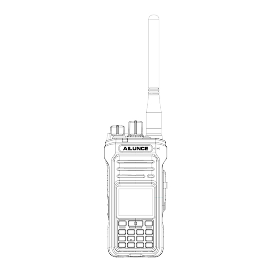
- Page 2 Fault Emission----- FCC Information---- Overview HA1G is the first GMRS radio of Ailunce brand, and is designed for GMRS radio fans. Ailunce HA1G IP67 waterproof GMRS two way radio, GMRS repeater capable, Type-C charging, 2800mAh long standby two way radio.
- Page 3 11. DO NOT use the battery if it emits an abnormal odor, heats, or is discolored or deformed. If any of these conditions occurs, contact your Ailunce dealer or distributor. 12. DO NOT use the battery pack out of the specified temperature range –10˚C ~ +45˚C. Using the pack out of this range will reduce the battery pack’s performance and affect the battery cell...
- Page 4 6. DO NOT charge the battery pack out of the specified temperature range: 10˚C ~ 40˚C (32˚F ~ 104˚F). Ailunce recommends charging the pack at 25˚C (77˚F). The battery pack may overheat or rupture if charged out of the specified temperature range. Additionally, the battery performance or the battery life may be reduced.
- Page 5 2. Install / Uninstall the Belt Clip...
- Page 6 Place the belt clip to the corresponding grooves on the back of the radio, and then screw it if need. Anticlockwise turn screws to remove the belt clip. Feature Summary 30 GMRS Channels Up to 250 Custom Channels ...
- Page 7 Low Battery Alert 2 Programmable Function Keys IP67 Waterproof 2800mAhType-C Charging battery Familiar with Radio 1. Parts of the radio...
- Page 8 2. Menu Icon Display...
- Page 9 Icon Description Signal bar; Speaker Lock Earpiece Scan Monitor Emergency FM broadcast radio NOAA Charging battery indicator channel number in the zone zone number Frequency, CH number, CH name display; CH number VOX on TA/FI : Talk around/ Reverse frequency CTCSS Tone Type TX Power Shift Direction +/-...
- Page 10 Custom Side-Key Function You can custom set below functions on the radio: High/Low power, turn on/off scan, FM radio, VOX, Zone +/ -, Sub PTT; 4. Key Function Instruction Menu Menu/ Confirm button Exit Exit menu; Long press [Exit] switch MR/VFO mode. Up/Down up/down through channels and menu settings;...
- Page 11 Band Setting Here choose displays, single band or dual band. Press Menu to enter Band Set. Up and Down keys to choose Band A or Band B. If stop at Band A, press the menu Key to choose and cancel this choice. 3.
- Page 12 3) Turn channel knob to set the VOX delay time. The maximum delay time can be set to 2000ms. 7. Power Save this feature significantly reduces quiescent battery drain, and you may notreceive the full data burst. 1) Turn channel knob to choose power save mode None,1:4,1:6,1:8; default is 1:4.
- Page 13 and When the cursor moves to the last character, press [EXIT] to delete the characters. Bandwidth You can choose the bandwidth for the current channel, default Wide for channel 1-7 and 15-30 GMRS channels, and you can change to bandwidth for these channels. Default unchangeable Narrow for 8-14 GMRS channels.
- Page 14 123.0 127.3 131.8 136.5 141.3 146.2 151.4 156.7 159.8 162.2 165.5 167.9 189.9 192.8 196.6 199.5 203.5 206.5 210.7 218.1 225.7 229.1 233.6 241.8 250.3 254.1 DCS CODE 6) Squelch level. The Squelch system allows you to mute the background noise when no signal is being received.
- Page 15 Set current channel transmit power, default high power for channel 1-7 and 15-30, default low power for channel 8-14. 8) TX Permission Set Set the transmit permission and transmit time and timer. In this menu, rotate the channel knob to adjust the TOT time. Press up and down key to choose the transmit permission options: CTC/CDC Match,Channel free,Receive only,Always allow.
- Page 16 ⑨ Hang time: Set the hang time if the scan carrier disappear. Rotate the channel knob to adjust the time. Signaling 1) Common Setting. PTT ID setting. ① Up and down key to set the PTT ID type, Side tone, BOT and EOT. ②...
- Page 17 or decode. ⑦ Default 4 DTMF systems list on the radio. Emergency ① Emergency System Alias Named emergency system same operation with the channel Alias. When the cursor is behind a character, press [EXIT] to delete the character. ② Alarm Type. choose the emergency call type: Siren Only: Only alarm sound, will not transmit.
- Page 18 2. NOAA Channel List. Up and down to choose the NOAA channel, and press [MENU] to confirm select this channel, and check the NOAA channel info. FM Radio The receiving frequency range of the FM radio is 76~108 MHz. Shortly press the Up key or Down key to increase the receiving frequency by 2MHz.Rotate the Channel knob to increase the receiving frequency by 0.1MHz.
- Page 19 ④ Under CH mode, Long press [*SCAN] button will start scanning the channels in the current scan list. But firstly, these channels need to add this scan list in the channel setting. ⑤ Under VFO mode, long press [*scan] button will start scanning the frequency according to the frequency step.
- Page 20 8. DTMF 1. DTMF decoding ① Press [MENU] to enter Signal Decode setting. ② Stun Type:If choose Stun Rx, means you allow others to disable your radio receiving with the Stun ID, and you can still transmit. If choose Stun TX/RX, means you allow others to disable your radio transmitting and receiving with the Stun ID, then you cant transmit and receive.
- Page 21 The PTT ID is not transmitted. You can transmit the PTT ID when pressing the PTT begin of the transmit. You can transmit the PTT ID when pressing the PTT end of the transmit. Both You can transmit the PTT ID when pressing/releasing the PTT. GMRS Frequency Table CH Name Frequency...
- Page 22 GMRS-12 467.66250 467.66250 Narrow GMRS-13 467.68750 467.68750 Narrow GMRS-14 467.71250 467.71250 Narrow GMRS-15 462.55000 462.55000 Wide High/Low Optional GMRS-16 462.57500 462.57500 Wide High/Low Optional GMRS-17 462.60000 462.60000 Wide High/Low Optional GMRS-18 462.62500 462.62500 Wide High/Low Optional GMRS-19 462.65000 462.65000 Wide High/Low Optional GMRS-20 462.67500...
- Page 23 Specifications List as follows: General TX Frequency Range 462~467Mhz Working Voltage DC 7.4V Working Temperature -10℃~+50℃ Battery Capacity 2800mAh 50Ω Antenna Impedance Bandwidth mode 12.5KHz/25KHz; Transmitter ≤36dBm Output Power Wideband : ≤-65dBc ; Narrowband : ≤-62dBc Adjacent Channel Power Wideband : 0.75KHz± 0.1KHz; CTCSS/CDCSS Modulation Narrowband :...
- Page 24 The list aims at helping you correct the problems that don’t belong to the device’s fault. If you can’t find out the reason for problems or can’t work them out, please contact your seller or customer service. As follow email address:hams@ailunce.com. The battery is Charge the battery pack, or replace the batteries.
- Page 25 Exposure awareness can be facilitated by the use of a product label directing users to specific user awareness information. Your Ailunce two-way radio has a RF Exposure Product Label. Also, your Ailunce user manual, or separate safety booklet includes information and operating instructions required to control your RF exposure and to satisfy compliance requirements.
- Page 26 When operating in front of the face, worn on the body, always place the radio in a Ailunce approved clip, holder, holster, case, or body harness for this product. Using approved body-worn accessories is important because the use of Non-Ailunce approved accessories may result in exposure levels, which exceed the IEEE/ICNIRP RF exposure limits.
- Page 27 •DO NOT operate the transmitter in areas that are sensitive to electromagnetic radiation such as hospitals, aircraft, and blasting sites. •Portable Device, this transmitter may operate with the antenna(s) documented in this filing in Push-to-Talk and body-worn configurations. RF exposure compliance is limited to the specific belt-clip and accessory configurations as documented in this filing and the separation distance between head and the device or its antenna shall be at least 2.5 cm.
- Page 28 •The adapter shall be installed near the equipment and shall be easily accessible Approved Accessories •This radio meets the RF exposure guidelines when used with the Ailunce accessories supplied or designated for the product. Use of other accessories may not ensure compliance with the RF exposure guidelines and may violate regulations.
Need help?
Do you have a question about the HA1G and is the answer not in the manual?
Questions and answers