Table of Contents
Advertisement
Quick Links
© 2012
ALLIED AIR ENTERPRISES
215 METROPOLITAN DR.
WEST COLUMBIA, SC 29170
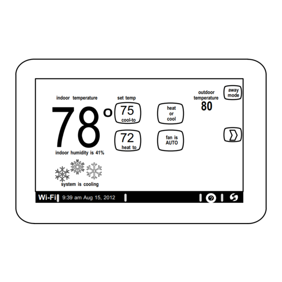
indoor temperature
set temp
75
72
indoor humidity is 41%
system is cooling
Wi−Fi
9:39 am Aug 15, 2012
THIS MANUAL MUST BE LEFT WITH THE HOMEOWNER
FOR FUTURE REFERENCE
NOTICE
Read this manual before programming this thermostat.
Use this thermostat only as described in this manual.
11/12
*2P1112*
outdoor
temperature
80
heat
or
cool
cool−to
fan is
AUTO
fan is
fan is
heat to
AUTO
OFF
?
INSTALLER'S SYSTEM SETUP
GUIDE
Comfort Synct Thermostat
Touch Screen Programmable Communicating Thermostat
CONTROLS
away
mode
507064−01
11/12
Supersedes 09/12
Comfort Sync−Enabled Units
A97USMV
4SCU18LS
BCS2M_S
Shipping and Packing List
1 −
Comfort Synct thermostat
4 −
Mounting Screws
4 −
Wall Anchors
1 −
Installation Quick-Start Guide
1 −
Installer's System Setup Guide
1 −
Homeowner's Manual
1 −
Warranty card
A97DSMV
A80US2V
4SHP18LS
4SCU16LS
507064−01
*P507064-01*
A80DS2V
4SHP16LS
Advertisement
Table of Contents

Related Manuals for Comfort Sync A97USMV


Summary of Contents for Comfort Sync A97USMV
- Page 1 507064−01 11/12 heat Supersedes 09/12 cool cool−to fan is AUTO fan is fan is Comfort Sync−Enabled Units heat to AUTO indoor humidity is 41% A97USMV A97DSMV A80US2V A80DS2V 4SCU18LS 4SHP18LS 4SCU16LS 4SHP16LS BCS2M_S system is cooling Wi−Fi...
-
Page 2: Table Of Contents
Setting up typical Comfort Sync systems Table of Contents Page Indoor Unit Outdoor Unit page Technical Description/Features ........ -
Page 3: Technical Description/Features
1. supports three languages (English, French, Spanish), The Comfort Sync thermostat can connect to online services via the internet supports air conditioning units or heat pump units with up to four stages through the homeowner’s Wi−Fi access point. -
Page 4: Installation And Setup
Page 59 of this manual.) press edit Time and Date NOTE − If electric heat strips are used with an Comfort Sync−enabled air han- current value: Daylight Saving Time dler, the strips MUST be configured on the air handler control (AHC) board... -
Page 5: Change Settings (Dealer Info, Daylight Savings, Fan Circulate)
Change settings in figure 3. (Also, see Set time and date on Page 7.) After changes have been made, use save to store the changed data or cancel to exit the screen If you want to change a setting, use one of the Settings change tools shown and return to the list of settings. - Page 6 Circulate fan ON time setting Table 1. System setting defaults and range system range/ default NOTE − If the circulate fan mode is on, a timer is set to measure all the time setting condition that the fan is blowing, regardless if it is running to deliver heating or cooling or just for circulation.
-
Page 7: Set Time And Date
Set time and date Use the arrows to select Time and Date; press edit (see figure 4) to proceed When Time and Date" screen (figure 5) appears, enter the correct date as to the Set current time and date" screen (figure 5). follows: Use the left and right arrows to change the month and year. - Page 8 Use about" screen & access Add or Remove Non−communicating equipment" screen The about" screen shows details of discovered installed equipment. From the system devices" screen, use arrow buttons to scroll to a device; then press the about button. Use the up/down arrows to scroll through and view additional information about the selected device.
-
Page 9: Add Or Remove Non−Communicating Equipment
Wi−Fi when available (primary source), sensor furnished with Comfort Sync−enabled outdoor units, Adding Humidifier The procedures in figure 8 describe adding a non− separate outdoor sensor connected to the furnace or air handler communicating humidifier which will be controlled by the Comfort Synct outdoor sensor"... -
Page 10: Outdoor Unit
Add Non−Communicating Outdoor unit To add (or remove) an outdoor unit that is not Comfort Sync−enabled, you must be at the Add or Remove Non−communicating equipment?" screen. 1. Press the yes button on this screen (see 1). Add or Remove System Devices 2. -
Page 11: Humidifier
Add (or Remove) Humidifier (skip if no humidifier is being used) NOTE − Adding humidity regulating non−communicating devices may be a 2−step procedure: Before adding a humidifier, be sure that: S the humidifier is wired to the furnace or air handler control as shown on the Optional 1st, the device must be installed (this page;... -
Page 12: Dehumidifier
Add (or Remove) Auxiliary Dehumidifier (skip if no dehumidifying device is being used) Before adding a dehumidifier, be sure that: NOTE − Adding humidity regulating non−communicating devices may be a 2−step procedure: S the dehumidifier is wired to the furnace or air handler control as shown on the Option- 1st, the device must be installed (this page;... -
Page 13: Adjust A Setting Screen
Adjust a setting screen (communicating devices) Use arrows to select a device from the system devices" list; then use the about button to view information (shown on Page 8) about communicating devices (information about other devices is not available). Use resetAll button to un−install all non−communicating devices that were added through Add or Remove..." screen and to reset any device settings made through this Adjust a setting..."... - Page 14 A97MV Furnace Note: If your Comfort Synct thermostat is being used with a n A97MV furnace and is set to variable−capacity mode of operation (the Comfort Sync default with these units), the thermostat’s settings for stage timers are ignored (even if shown enabled in the thermostat). The stage timer will be used on the cooling side. The furnace software sets and controls the firing rates.
-
Page 15: Configure Humidifier
Adjust a setting... Configure Humidifier (skip if no humidifier is being used or if humidifier is being used and default Basic" humidification mode is desired) Pre−adjustment REQUIREMENTS: 1st, the device has been installed (see Page 11). System Devices To adjust a setting, highlight it, 2nd, you pressed next at the Add or Remove..."... -
Page 16: Configure Dehumidifier (Aux. Dehum. Installed)
Adjust a setting... Configure Auxiliary Dehumidifier Pre−adjustment REQUIREMENTS: To adjust a setting, system devices 1st, the device has been installed (see Page 12). highlight it, System about then press Edit 2nd, from the Add or Remove Non−communicating equipment?", press next. Air Conditioner 3rd, in the Adjust a setting..."... -
Page 17: Configure Dehumidification (No Dehumidifier Installed)
Adjust a setting... Configure Dehumidification (no dehumidifying device installed) (skip if default Basic" dehumidification mode is desired) Pre−adjustment REQUIREMENTS: System Devices To adjust a setting, highlight it, 1st, NO physical dehumidification device has been installed. then press Edit 2nd, configure the thermostat for dehumidification as follows: System 1. -
Page 18: Humidification And Dehumidification Modes How They Work
Auxiliary Dehumidifier mode requires: BASIC mode also requires presence of heating demand [Y for HP NOTE − Systems using Comfort Sync and a dehumidifier − Dehum" jumper heat, or W for gas heat (W may be energized with G de−energized)]. -
Page 19: Use The Test Features
Use the Tests / Diagnostics features NOTE − Test mode lasts for 30 minutes (with the temperature updating every select tests to run 30 seconds) except for the defrost test, which lasts 30 seconds. Tests fea- Blower ture provides the technician time to manually verify the equipment operation. HP Heat −... -
Page 20: Set Up Equipment Parameters
After pressing next after the final test, the Testing finished" screen will ap- Set up Equipment parameters pear (figure 19). At this point, use the EXIT button (if you have completed the Press equipment to set up equipment parameters and edit details of de- required setup), or use diagnostics button (to analyze the system), or use vices in the system without having to re−run the setup program. -
Page 21: Use The Diagnostic Features
When finished, press back; equipment parameters screen (figure 20B re- setup tests equipment turns); then press next. Select tests to run screen appears" (Page 19); ei- ther run tests as before or press skip tests. system devices Low Heating Airflow The Testing process screen"... -
Page 22: View And Clear Alerts
Press done when finished with the information. Select another device to From the user’s home screen, press and hold the Swoosh" logo in the bot- diagnose or use EXIT (to close and go to user Home screen) if finished. tom right corner of the thermostat to access the installer program. Press yes when asked if you want to proceed. - Page 23 setup tests equipment alerts diagnostics setup tests equipment System Devices system and device alerts System No Alerts Furnace Thermostat select all view active deselect all view cleared back 9:39 am Aug 15, 2012 EXIT 9:39 am Aug 15, 2012 Figure 24. Cleared alert confirmation setup tests equipment...
-
Page 24: Enable Wi−Fi From User Home Screen
Enable the thermostat’s Wi-Fi feature from the Home screen Secure Connection Recommended! network security key or passphrase press any line to edit it none Make sure the router is capable of, and set to operate in wire- displays information here as keys pressed network name (SSID) less network b"... -
Page 25: Register The Comfort Synct Thermostat
NOTE NETWORK’s marked with * - Selecting one of these wireless networks may result in an unreliable connection to your thermostat. Press help ?" for tips on improving signal strength. Register with Comfort Sync thermostat to enable remote access and online weather information choose a wireless network (returns to... -
Page 26: Personal Computer Account Registration To Comfort Synct Server
Congratulations on your purchase of an Allied Com- fort Sync thermostat! You are only a few steps away from total control of your Comfort Sync system. Reg- istering your thermostat will allow you to remotely ac- cess it from anywhere in the world on any device with an internet connection. - Page 27 Access all the great Wi−Fi enabled features on your Comfort Synct thermo- stat from our secure web portal. After signing in, you´ll be able to view your Comfort Sync system settings, adjust the temperature and view reminders and alerts ˘ just as you would on your Comfort Synct thermostat at home.
-
Page 28: Access Installer Program From User Home Screen
To access the installer program after the unit has been placed in operation A message screen stating Qualified Comfort Sync equipment installer and the user home screen is displayed, press the Comfort Sync logo and warning" screen appears (Figure 32). Press yes to proceed (no returns to hold for 5 seconds (see figure 31). -
Page 29: Reconfigure A System
Reconfigure a system If any component of the HVAC system has been changed, e.g. replacing an Press confirm (3, figure 33C) to continue system configuration; the screen outdoor sensor, reconfiguring the system will be required. To begin reconfi- will change to the system discovery screen. At this point, the program goes guring a system (after you have accessed the program from the Swoosh"... -
Page 30: Stage Delay Timers & Differentials
Stage Delay & Differential Settings (Installer settings) 1st Stage Differential Stage 1 differential is used in all thermostats. The previous stage of heating or cooling will not raise or lower the room tempera- default is 1.0°F but can be programmed between 0.5° and 3.0°F in 0.5°F in- ture to the setpoint in a given time. -
Page 31: Smooth Setback Recovery (Ssr)
Smooth Setback Recovery (SSR) SSR is an algorithm designed to smoothly" reach a occupied program Rules for SSR: schedule setpoint. The algorithm looks 2 hours ahead for the occupied pro- 1. SSR is enabled when Smooth Setback Recovery" is set to enabled gram schedule period’s setpoint. -
Page 32: Heat Pump, Dual Fuel And Balance Points
Wi−Fi (for local temperature information) or a connection ance point options are from −20°F to the high balance point temperature. The to an outdoor sensor (included in all communicating Comfort Sync−en- setpoint can be adjusted in 1.0°F steps. - Page 33 Shut down HP Abbreviations: Stg 1...Stg 2 FURN = auxiliary heat provided by gas furnace HP = compressor heat T’stat LBP = Low Balance Point heat HBP = High Balance Point demand T’stat = thermostat FURN NOTE 1 − Each Heat Pump and Furnace Heat stage will oper- heat Operate HP ate until it meets the demand or until its stage timer lapses (20...
-
Page 34: Gas Heat Control Mode
Gas Heat Control Mode Increase firing Differential Differential Differential rate to 100% THERMOSTAT less than 2nd stage less than 3rd stage less than 4th stage until thermostat DEMAND differential differential differential demand is satisfied Increase firing rate Increase firing rate Starting firing rate SYSTEM to calculated 2nd... - Page 35 Furnace is off capacity) is used. When in variable capacity gas heat mode, the furnace op- First level heat de- 1. Furnace BTU rate is calculated by the Comfort Sync integrat- eration includes longer run times at lower heat stages. mand.
- Page 36 Load−tracking Vari- The longer away from a programmed set point, the higher the heating able Capacity is only available with Comfort Sync Wi−Fi thermostats. rate. How is Load−tracking Variable Capacity different from Variable Ca-...
- Page 37 Table 3. Adjustable Parameters Table (Installer) Parameter Name: Default Parameter Value Setting Increment Installer entry System (Go to equipment button and scroll to System) NOTE − All of the following changes are made on the stat. Equipment Name (keyboard input screen) Filter 1 Timer Selection Calendar Time Calendar Time, Run Time...
- Page 38 Table 3. Adjustable Parameters Table (Installer) Parameter Name: Default Parameter Value Setting Increment Installer entry Lock in 2nd stage HP by Outdoor Temp Off, 40ºF (4ºC), 45ºF (7ºC), 50ºF (10ºC), 55ºF (13ºC) Balance Point Control Disabled Enabled, Disabled High Balance Point 50ºF −17ºF to 75ºF 1ºF...
- Page 39 Table 3. Adjustable Parameters Table (Installer) Parameter Name: Default Parameter Value Setting Increment Installer entry AIR HANDLER Equipment Name Air Handler (keyboard input screen) Electric Heating Airflow 5CFM nnnn CFM NOTE: CFM Default and Values Settings are depen- Low Cooling Airflow 5CFM (See Note 3 at dent on the tonnage of the unit...
- Page 40 Table 3. Adjustable Parameters Table (Installer) Parameter Name Default Min. Max. Incr. Dependency Note Installer entry FURNACE Heating indoor blower OFF delay DIP SW None DIP switch setting in Non−comm. Heating indoor blower ON delay 45 sec None 45 sec fixed in Non− Comm.
- Page 41 Table 3. Adjustable Parameters Table (Installer) Parameter Name Default Min. Max. Incr. Dependency Note Installer entry Cooling Airflow Settings High Cooling Airflow (CFM @ 100% OU tons Outdoor Unit 1/2 HP blower cool) 400CFM present 1 HP blower Low Cooling Airflow (CFM @ lowest (See Note 1 2+ stage Outdoor 1/2 HP blower...
- Page 42 Table 3. Adjustable Parameters Table (Installer) Parameter Name Default Min. Max. Incr. Dependency Note Installer entry Other Parameters Equipment Name Furnace None Up to 35 characters Continuous Indoor Blower Airflow DIP SW (See None 1/2 HP blower Note 3 at end of table) 1 HP blower Humidification Airflow...
- Page 43 Table 4. Adjustable Parameters Table (User) Parameter Name: Default Parameter Value Setting Increment Installer entry Time and Date * (Time/date elements screen) Daylight Saving Time * Enabled Enabled, Disabled auto auto, on, circulate System Name (keyboard input screen) SERVICE INFORMATION Dealer Name your dealer (keyboard input screen)
- Page 44 Table 4. Adjustable Parameters Table (User) Parameter Name: Default Parameter Value Setting Increment Installer entry Disabled, 3 Months, 6 Months, 12 Months, Filter 1 Timer Disabled 24 Months, Custom Time Disabled, 3 Months, 6 Months, 12 Months, Filter 1 Timer Disabled 24 Months, Custom Time Disabled, 3 Months, 6 Months, 12 Months,...
- Page 45 Critical (Stat) The thermostat cannot find an Comfort Thermostat did not find an Indoor Unit. Make sure there is an Comfort Sync indoor unit on the sys- Sync−enabled indoor unit. tem. Check R, i+, i− and C connections, ohm wires and cycle power. Replace indoor unit control board if there is no response.
- Page 46 Critical alerts are displayed on Home (user) screen, in the Homeowner alert button, and in the Installer Table 5. Alert Codes and Troubleshooting alert button. Minor and Moderate alerts are found only in the Installer alert button. Alert Priority Alert Text Steps to clear Code Critical...
- Page 47 Critical alerts are displayed on Home (user) screen, in the Homeowner alert button, and in the Installer Table 5. Alert Codes and Troubleshooting alert button. Minor and Moderate alerts are found only in the Installer alert button. Alert Priority Alert Text Steps to clear Code Critical...
- Page 48 Critical alerts are displayed on Home (user) screen, in the Homeowner alert button, and in the Installer Table 5. Alert Codes and Troubleshooting alert button. Minor and Moderate alerts are found only in the Installer alert button. Alert Priority Alert Text Steps to clear Code Critical...
- Page 49 Critical alerts are displayed on Home (user) screen, in the Homeowner alert button, and in the Installer Table 5. Alert Codes and Troubleshooting alert button. Minor and Moderate alerts are found only in the Installer alert button. Alert Priority Alert Text Steps to clear Code Critical...
- Page 50 Critical alerts are displayed on Home (user) screen, in the Homeowner alert button, and in the Installer Table 5. Alert Codes and Troubleshooting alert button. Minor and Moderate alerts are found only in the Installer alert button. Alert Priority Alert Text Steps to clear Code Critical...
- Page 51 Critical alerts are displayed on Home (user) screen, in the Homeowner alert button, and in the Installer Table 5. Alert Codes and Troubleshooting alert button. Minor and Moderate alerts are found only in the Installer alert button. Alert Priority Alert Text Steps to clear Code Critical...
- Page 52 Critical alerts are displayed on Home (user) screen, in the Homeowner alert button, and in the Installer Table 5. Alert Codes and Troubleshooting alert button. Minor and Moderate alerts are found only in the Installer alert button. Alert Priority Alert Text Steps to clear Code Critical...
- Page 53 Critical alerts are displayed on Home (user) screen, in the Homeowner alert button, and in the Installer Table 5. Alert Codes and Troubleshooting alert button. Minor and Moderate alerts are found only in the Installer alert button. Alert Priority Alert Text Steps to clear Code Critical...
- Page 54 Critical alerts are displayed on Home (user) screen, in the Homeowner alert button, and in the Installer Table 5. Alert Codes and Troubleshooting alert button. Minor and Moderate alerts are found only in the Installer alert button. Alert Priority Alert Text Steps to clear Code Moderate...
- Page 55 (see Page 64 or Air Handler manual for details). does not offer a emerg. heat choice Handler Control (AHC) before the − Re−setup the Comfort Sync system by selecting the setup button in on an HP system. Comfort Synct system discov- the Installer program and press start to begin system discovery;...
- Page 56 Humidification mode (only Basic and outdoor sensor. − Comfort Sync system is not able to read the outdoor temperature Precision choices). sensor in the Comfort Sync outdoor unit, check outdoor sensor. The Comfort Sync does not display...
- Page 57 During system discovery, the ther- The thermostat was not success- − Verify the indoor unit has a Comfort Sync communicating control. mostat displays a message Thermo- ful in communicating to the indoor − Check wiring connections at R, i+, i− and C at the indoor unit and stat is unable to communicate to unit.
- Page 58 − No second stage cooling is pro- The red Critical Alert icon and − Go to the installer program alert button to view all alerts and details vided on a Comfort Sync outdoor homeowner alert button do not about those alerts.
-
Page 59: Wiring Diagrams
PUMP UNIT RSBus RSBus Comfort Synct Thermostat Comfort Sync Indoor Furnace or Air Handler Maximum total length of all connections on Outdoor Condensing Unit or Heat Pump the RSBus is limited to 1500ft. Wire gauge of RSBus wire is 18. - Page 60 Wiring Diagrams Comfort Sync Communicating Indoor/non−Communicating Outdoor System Wiring Comfort Sync AIR HANDLER (AHC) Comfort Sync FURNACE (IFC) OR AIR HANDLER (AHC) OPTIONAL DIS- OPTIONAL DIS- OPTIONAL OUT- CHARGE AIR SEN- OPTIONAL OUT- CHARGE AIR SEN- DOOR AIR SENSOR SOR (SEE DAS...
- Page 61 AIR HANDLER (AHC) OPTIONAL OUTDOOR AIR SENSOR FOR USE WITH HUMIDIFIER (IF NOT ALREADY IN THE SYSTEM FOR (SEE OAS NOTE Page 59) OTHER FUNCTIONS. BUILT INTO ALL Comfort Sync OUTDOOR UNITS). DISCHARGE AIR SEN- HCWH−01 For A80_2V, see HUMIDIFIER diagram below (bot-...
- Page 62 Comfort Sync LVCS. Set cycle time to 1 hour; set ventilation time to 60 minutes. installation Furnace or Air Handler details NOTE: Use the Comfort Sync circulate fan percentage of ON* TIME to control ventilation time. 507064−01 11/12 Page 62...
-
Page 63: Thermostat Wire Termination In Communicating System
Thermostat wire termination in communicating system Outdoor Unit Indoor Unit Controller Comfort Synct thermostat Single wire to terminal C Single wire to terminal C Unused wires Unused wires Communicating systems using the Comfort Synct thermostat require four Use wire nuts to bundle the unused wires at each end of the cable. A single thermostat wires between the thermostat and the furnace/air handler control wire should then be connected to the indoor unit end of the wire bundle and and four wires between the outdoor unit and the furnace/air handler control. - Page 64 Configuring heat strips on Air Handler Control (AHC) IMPORTANT: After electric heat strips are installed, the Air Handler Control FUSE 3 AMP HEAT (AHC) must be manually configured to detect the number of electric heat HUMIDITROL sections. (SEE ALSO Air Handler installation manual for configuration de- 1 2 3 4 XFMR 24V tails.)
- Page 65 4−conductor thermostat wire from the integrated furnace control 7. Press the start button. Confirm the AC unit is electrically energized and (IFC) terminal strip to the Comfort Sync−enabled AC unit (R, i+, i−, operational. Press done. Wiring as required for accessories 8.
- Page 66 Conventional thermostat wire with 2 to 4 conductors from the next step to advance to the tests button. Comfort Sync furnace terminal strip to the AC unit (Y1, C, & on 8. Using up/down arrows, select the test options individually (if so de- some models, R &...
- Page 67 Setting up typical systems FURNACE & HEAT PUMP (DUAL FUEL) Comfort Sync−enabled Furnace & Comfort Sync−enabled HP unit (Dual fuel) Dual fuel system using a Comfort Sync−enabled gas furnace (A97_SMV, When all CFM settings are complete, press the back button. Press A80_S2V) with a Comfort Sync−enabled heat pump (4SHP16LS or...
- Page 68 NOTE − IMPORTANT! Be sure to configure the air handler control so that When all CFM settings are complete, press the back button. Press heat strips (if used) information will be detected by the Comfort Sync thermo- next step to advance to the tests button.
- Page 69 Particularly, test the heat strips (when used) to to the air handler (R, i+, i−, C) insure the auxiliary stages have been detected and are operational. Comfort Sync air handler to conventional AC (5 – 8 wires). (Y1, Press done. Y2, C, R, W1,W2) 11.
- Page 70 Enabled and then save. vice list using the up/down arrows and press the edit button An outdoor temperature sensor is provided in an Comfort Sync en- 6. Select Balance Point Control and press edit. Use the down arrow to abled heat pump unit.
- Page 71 Comfort Sync−enabled Air Handler & conventional non−communicating Heat Pump unit A Comfort Sync−enabled air handler (BSC2M_S) with a conventional non− each setting. The red settings will go away after pressing save. Press communicating heat pump unit. the back button to return to the adjust screen.
- Page 72 REVISION HISTORY Date Revision description 07−2012 Preliminary release (Draft 1) 09−2012 Draft 2 507064−01 11/12 Page 72...
Need help?
Do you have a question about the A97USMV and is the answer not in the manual?
Questions and answers